

Gladiator GAWUXXGFTG, GAWUXXBLTH, GAWU12CCTG, GAKT48SLGY, GAKT32GFGG Installation Instructions
...Page 1

BALL, GOLF AND
Warranty.......................................................................................................................................................................................................................6
CLEAN-UP CADDY
Installation Instructions
Instructions d’installation
Instrucciones de instalación
TABLE OF CONTENTS
BALL, GOLF & CLEAN-UP CADDY
BALL, GOLF & CLEAN-UP CADDY INSTALLATION INSTRUCTIONS
Mount the Ball Caddy to GearTrack® Channels or GearWall® Panels..................................................................................................................................................................3
Assemble Ball Caddy
Assemble Golf Caddy.................................................................................................................................................................................................4
Mount the Golf Caddy to the wall...........................................................................................................................................................................................................................................4
Assemble Clean-up Caddy.........................................................................................................................................................................................6
Mount the Clean-up Caddy to the wall.............................................................................................................................................................................................................................6
..................................................................................................................................................................................................3
INSTALLATION SAFETY ...................................................................................................................................2
.........................................................................................................
TABLE DES MATIÈRES
SÛRETÉ DES INSTALLATIONS DU CASIER À ACCESSOIRES POUR NETTOYAGE, DU CASIER DE GOLF ET DU PANIER POUR BALLONS ...8
SÛRETÉ DES INSTALLATIONS DU CASIER À ACCESSOIRES POUR NETTOYAGE, DU CASIER DE GOLF ET DU PANIER POUR BALLONS ...8
Montage du panier pour ballons aux prolés GearTrack® ou aux panneaux GearWall® ..................................................................................... 9
Assemblage du panier pour ballons ....................................................................................................................................................................... 9
Assemblage du casier de golf .............................................................................................................................................................................. 10
Montage du casier de golf sur le mur ................................................................................................................................................................... 10
Assemblage du casier à accessoires pour nettoyage ......................................................................................................................................... 12
Montage du casier à accessoires pour nettoyage sur le mur ............................................................................................................................. 12
Garantie ..................................................................................................................................................................................................................... 12
ÍNDICE
SEGURIDAD PARA LA INSTALACIÓN DEL CONTENEDOR PARA PELOTAS, ARTÍCULOS DE GOLF Y ARTÍCULOS DE LIMPIEZA ...........14
INSTRUCCIONES PARA LA INSTALACIÓN DEL CONTENEDOR PARA PELOTAS, ARTÍCULOS DE GOLF Y ARTÍCULOS DE LIMPIEZA ..14
Monte el contenedor para pelotas en canales GearTrack® o paneles GearWall® ............................................................................. 15
Ensamble el contenedor para pelotas ............................................................................................................................................... 15
Ensamble el contenedor para artículos de golf ................................................................................................................................. 16
Monte el contenedor para artículos de golf en la pared .................................................................................................................... 16
Ensamble el contenedor para artículos de limpieza .......................................................................................................................... 18
Monte el contenedor para artículos de limpieza en la pared............................................................................................................. 18
Garantía .................................................................................................................................................................................................. 18
2
In U.S.A. call: 1-866-342-4089
W11129385A
Aux É.-U. : 1 866 342-4089
En EE.UU. Ilame al: 1-866-342-4089
In Canada call: 1-800-807-6777
Au Canada : 1 800 807-6777
En Canadá Ilame al: 1-800-807-6777
www.gladiatorgarageworks.com
www.gladiatorgarageworks.ca
Page 2
BALL, GOLF AND CLEAN-UP CADDY INSTALLATION
SAFETY
Your safety and the safety of others are very important.
We have provided many important safety messages in this manual and on your appliance. Always read and obey all safety
messages.
This is the safety alert symbol.
This symbol alerts you to potential hazards that can kill or hurt you and others.
All safety messages will follow the safety alert symbol and either the word “DANGER” or “WARNING.”
These words mean:
You can be killed or seriously injured if you don't immediately
DANGER
WARNING
All safety messages will tell you what the potential hazard is, tell you how to reduce the chance of injury, and tell you what can
happen if the instructions are not followed.
follow instructions.
You
can be killed or seriously injured if you don't
instructions.
follow
BALL, GOLF AND CLEAN-UP CADDY
INSTALLATION INSTRUCTIONS
Parts Maximum Weight Limit Tools and Parts Required
Ball Caddy 25 lbs (11.3 kg) N/A
25 lbs (11.3 kg) for the shoe shelf
Golf Caddy
Clean-Up Caddy 25 lbs (11.3kg)
IMPORTANT : Intended to be installed on Gladiator® Garageworks GearWall® panels or GearTrack® channels.
NOTES :
1. Be sure the Gladiator® GearWall® panel or GearTrack® channel is installed with mounting screws in every slot and at every stud
location with a maximum of 24” (60.96 cm) horizontally between screws.
2. Remove the caddies parts and fasteners, and dispose of/recycle all packaging materials.
50 lbs (22.7 kg) for the golf bag shelf
75 lbs (34.0 kg) for the golf bag caddy
3
/8” (9.52 mm) nut driver, 1/2” (1.27 cm) nut
driver, Phillips- head screwdriver,Hex Key
3
/8” (9.52 mm) Nut driver, Phillips
screwdriver
2
Page 3
BALL CADDY
A
B
B
B
A
Mount the Ball Caddy to
GearTrack® channel or
GearWall® panel for Assembly
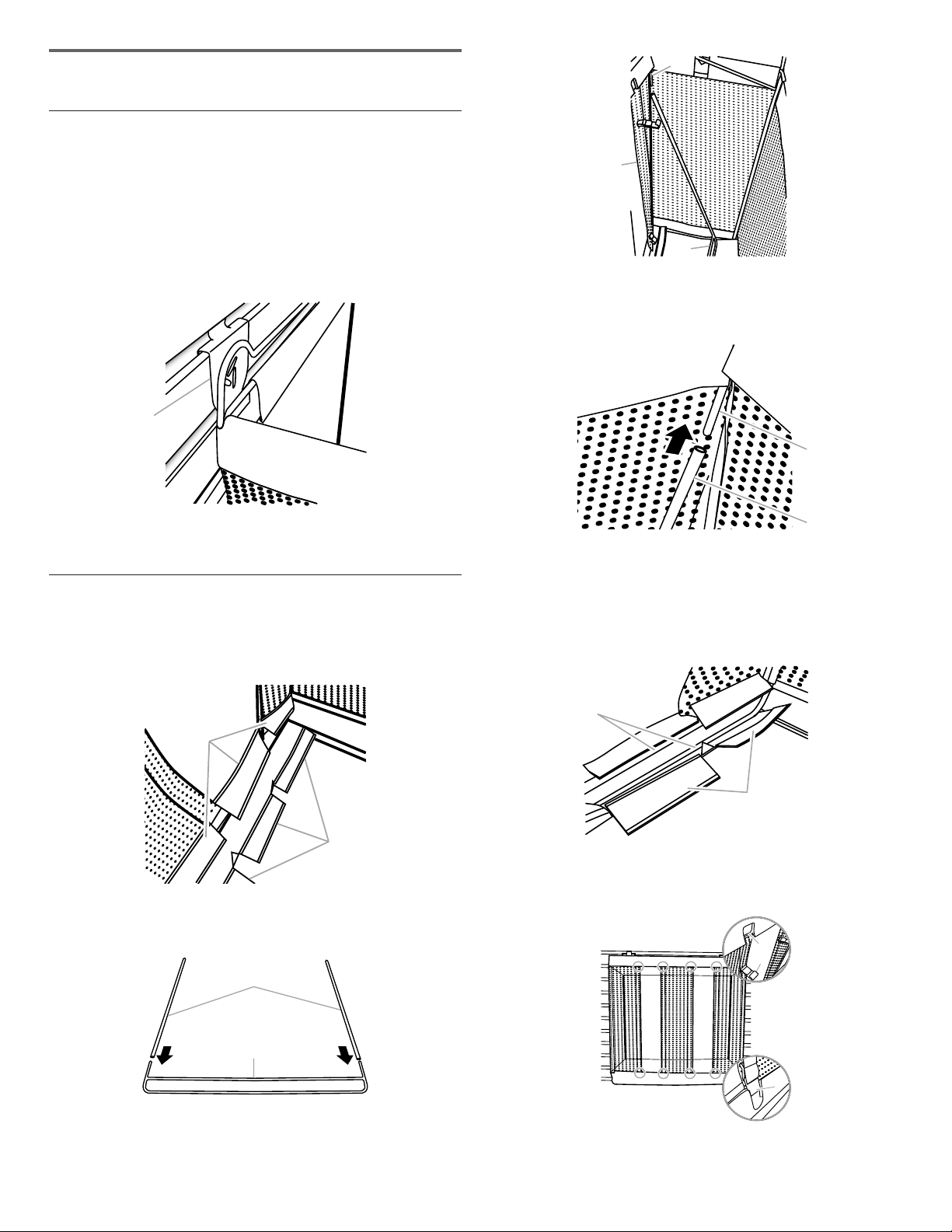
1. Align the mounting brackets, one on each side of the rear
frame, with the desired slots in the GearWall® panel or
GearTrack® channel.
2. Engage the bracket rims into the slots in the GearWall® panel
or GearTrack® channel by lifting up, pushing toward the wall
and lowering the rims into the slots.
A
A
B
C
A. Upper frame
B. Ball caddy front
4. Slide the hollow metal rods that are joined to the lower frame,
onto each end of the upper frame, as shown.
C. Lower frame
A. Mounting bracket
3. Inspect the ball caddy from the side to ensure the bracket
rims are fully engaged in the slots.
Assemble Ball Caddy
IMPORTANT : Before assembling, rst mount the ball caddy
to GearWall® panel or GearTrack® channel.
1. Reach inside the ball caddy and unfasten the fabric closures
running along the bottom front of the caddy.
A
A
A. Fabric closures
2. Slide the hollow metal rods onto each end of the lower frame,
as shown.
A. Upper frame
B. Ball caddy front
5. Pull the lower frame forward until it is between the fabric
closures at the bottom of the ball caddy. Fasten the fabric
closures around both cross bars of the lower frame.
NOTE : Make sure the fabric closures are fastened tightly
around both the upper and lower crossbars of the frame.
A
B
A. Crossbar
B. Fabric closures
6. Attach the eight hooks, one on each end of the four elastic
straps, onto the upper and lower frame, as shown.
A
3. Holding the lower frame where it is joined with the metal rods,
place the frame, bottom edge down, into the ball caddy at an
angle.
B
A. Hollow metal rod
B. Lower frame
A. Upper frame
B. Hook
3
Page 4
GOLF CADDY
D
E
A
B
C
C
B
A
B
18" (46 cm
Assemble Golf Caddy
4. Repeat steps 1 through 3 to attach the lower mounting
bracket.
NOTE : Hand tighten the nuts attaching the lower bracket.
In order to mount the golf caddy on the wall, this bracket will
need to be adjusted.
5
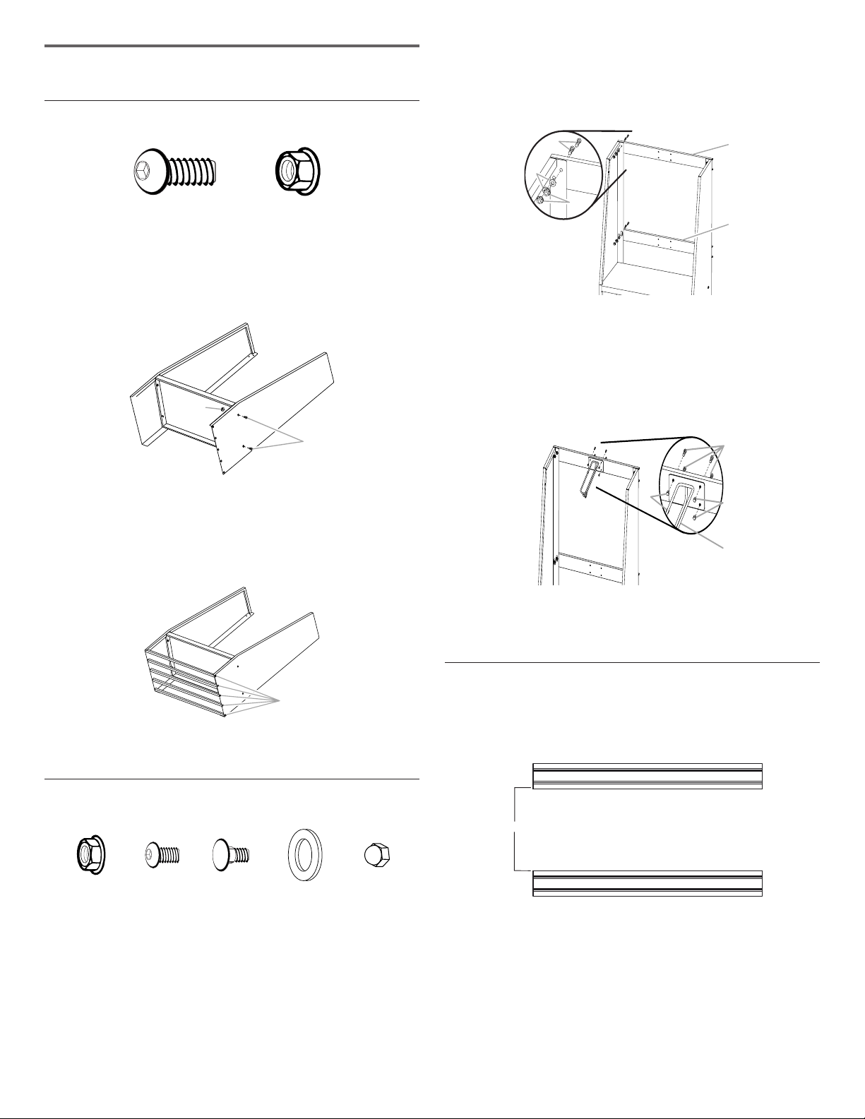
F1:
hex-head bolt (14)
1. Using 5/16” (7.93 mm) hex-head bolts (F1) and 5/16” (7.93 mm)
ange nuts (F2), attach the golf bag shelf to the sides as
shown.
2. Create a shoe shelf by using 5/16” (7.93 mm) hex-head bolts
(F1), to attach the 5 rods to both sides of the golf caddy, as
shown.
F1
/16” (7.93 mm)
A
A. 5/16” (7.93 mm) ange nut (F2)
B. 5/16” (7.93 mm) hex-head bolt (F1)
F2
F2: 5/16” (7.93 mm)
ange nut (4)
B
A. Carriage-head bolts (F7)
B. Washer (F8)
C. Flange nuts (F2)
5. Using Phillips-head screws (F3b) and acorn nuts (F10), attach
the golf bag divider to the 4 holes in the center of the upper
mounting bracket.
A. Phillips-head screws (F3b)
B. Acorn nuts (F10)
D. Upper mounting bracket
E. Lower mounting bracket
C. Golf bag divider
3. Stand the golf caddy upright.
F2 F3b F7
1. With the mounting bracket rims pointing down, align the 2
2. Working from the back, insert a carriage-head bolt (F7)
3. Working from the front, fasten each bolt with a washer (F8)
A
A. 5/16” (7.93 mm) hex-head bolt (F1)
Attach Mounting Brackets
5
F2
/16” (7.93 mm)
ange nut (8)
F3b Phillips-head screw (4)
F7 Carriage-head bolt (8)
bracket holes with the top two holes in each side.
through the holes in the bracket and into the side.
and a ange nut (F2). Completely tighten the nuts.
F8 F10
F8 Washer (8)
F10 Acorn nut (4)
Mount the Golf Caddy to the
Wall
IMPORTANT : If Gladiator® GearTrack® channels will be used
to mount the golf caddy, they must be installed 18” (46 cm)
apart.
)
1. Determine caddy mounting location on GearWall® panel or
GearTrack® channels.
2. Engage the upper mounting bracket into the wall slots by
lifting up, pushing toward the wall and lowering the bracket
rims into the slots.
3. Inspect the golf caddy from the side to ensure the upper
mounting bracket rims are fully engaged in the slots as
shown.
4
Page 5
A
B
C
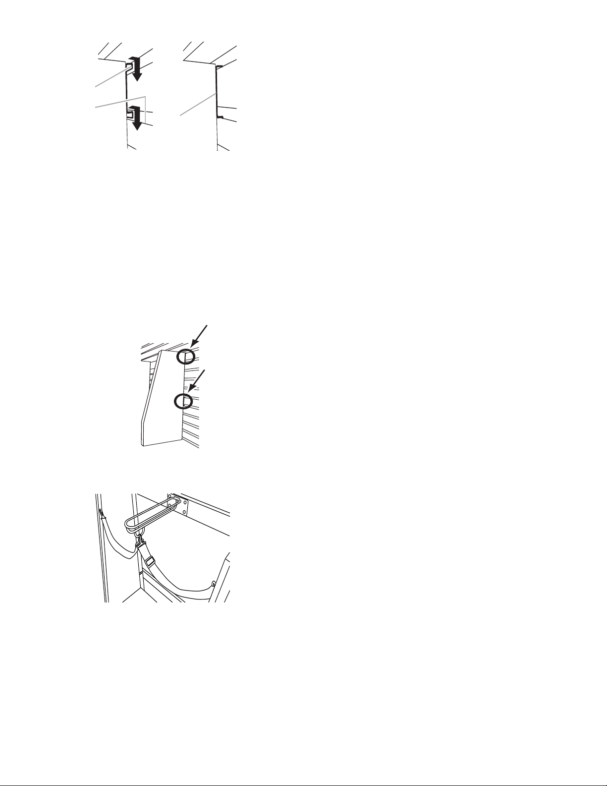
A. Bracket rim
B. Slot
4. Grasping the bolts, lift up on the lower mounting bracket to
align the bracket rims with the slots on the GearWall® panel or
GearTrack® channel.
5. Push the golf caddy toward the wall and lower the lower
bracket rims into the slots.
NOTE : Make sure the lower mounting bracket is fully
engaged in the slots.
6. Using a 1/2” (1.27 cm) wrench, tighten the nuts on the lower
mounting bracket.
7. Inspect the golf caddy from the sides to ensure both the
upper and lower mounting brackets are fully engaged in their
respective slots as shown.
C. Mounting bracket fully
engaged
8. Attach each strap to the side panel and to the D-ring on the
golf bag divider, as shown.
5
Page 6

CLEAN-UP CADDY
Assemble Clean-Up Caddy
F3b
F3b Phillips-head screw (2)
1. Insert the threaded studs at the top of each side piece into the
two holes in each side of the caddy back.
NOTE : Make sure the bracket rim on the caddy back is to the
outside of the side pieces.
2. Using two acorn nuts (F10) per side, attach the sides to the
back. Completely tighten with a 3/8” (9.52 mm) nut driver.
F10
F10 Acorn nut (6)
A
5. Holding each screw in place with a screwdriver, completely
tighten the acorn nut with the nut driver.
Mount the Clean-Up Caddy to
the Wall
1. Engage the bracket rims located on the back of the caddy
into the slots in the GearWall® panel or GearTrack® channel by
lifting up, pushing toward the wall and lowering the rims into
the slots.
2. Inspect the caddy from the side to ensure the bracket rims are
fully engaged in the slots as shown.
A. Acorn nuts (F10)
3. Attach the caddy shelf (with the name badge facing up) by
interlocking the shelf tabs with the tabs on the back.
NOTE : Make sure the lower mounting bracket is fully
engaged in the slots.
A
A. Bottom piece
4. Using the two Phillips-head screws (F3b) and two acorn nuts
(F10) fasten the caddy shelf to the sides.
WARRANTY
For warranty information:
In U.S.A. call 1-866-342-4089 or visit our website at
www.GladiatorGW.com
In Canada call 1-800-807-6777 or visit our website at
www.gladiatorgarageworks.ca
There are many benets for registering the product. Find out more
and register the product online at
www.gladiatorgarageworks.com.
A
A. Phillips-head screw (F3b)
B. Acorn nut (F10)
B
6
Page 7

NOTES
7
Page 8

SÛRETÉ DES INSTALLATIONS DU CASIER À ACCESSOIRES POUR
NETTOYAGE, DU CASIER DE GOLF ET DU PANIER POUR BALLONS
Votre sécurité et celle des autres est très importante.
Nous donnons de nombreux messages de sécurité importants dans ce manuel et sur votre appareil ménager. Assurez-vous de
toujours lire tous les messages de sécurité et de vous y conformer.
Voici le symbole d’alerte de sécurité.
Ce symbole d’alerte de sécurité vous signale les dangers potentiels de décès et de blessures graves à vous
et à d’autres.
Tous les messages de sécurité suivront le symbole d’alerte de sécurité et le mot “DANGER” ou
“AVERTISSEMENT”. Ces mots signifient :
Risque possible de décès ou de blessure grave si vous ne
DANGER
AVERTISSEMENT
Tous les messages de sécurité vous diront quel est le danger potentiel et vous disent comment réduire le risque de blessure et
ce qui peut se produire en cas de non-respect des instructions.
suivez pas immédiatement les instructions.
Risque possible de décès ou de blessure grave si vous
ne suivez pas les instructions.
SÛRETÉ DES INSTALLATIONS DU CASIER
À ACCESSOIRES POUR NETTOYAGE, DU CASIER
DE GOLF ET DU PANIER POUR BALLONS
Pièces Limite de poids maximum Outils et pièces requis
Panier pour ballons 25 lb (11,3 kg) N.D.
25 lb (11,3 kg) pour la tablette à
chaussures
Casier de golf
Casier à accessoires pour nettoyage 25 lb (11,3 kg) Tourne-écrou de 3/8” (9,52 mm), tournevis
IMPORTANT : Produit conçu pour une installation sur des panneaux Gladiator® Garageworks GearWall® ou des prolés GearTrack®.
REMARQUE :
1. Vérier que lors de l’installation des panneaux GearWall® ou des prolés GearTrack® Gladiator®, une vis de montage a été placée
dans chaque rainure au niveau de chaque poteau du colombage, avec intervalle horizontal maximum de 24” (60,96 cm) entre les vis.
2. Retirer les composants et pièces d’assemblage du casier; jeter ou recycler les matériaux d’emballage.
50 lb (22,7 kg) pour la tablette à sac de
golf
75 lb (34,0 kg) pour le casier de golf
Tourne-écrou de3/8” (9,52 mm), tourneécrou de 1/2” (1,27 cm), tournevis à tête
cruciforme, clé à tête hexagonale
à tête cruciforme
8
Page 9

PANIER POUR BALLONS
A
B
B
B
A
Fixer le panier pour ballons au
prolé GearTrack® ou au panneau
GearWall® pour le montage
1. Aligner les supports de montage, un sur chaque côté du cadre
arrière avec les rainures de l’emplacement désiré sur le panneau
GearWall® ou sur le prolé GearTrack®.
2. Engager les rives d’accrochage dans les rainures du panneau
GearWall® ou du prolé GearTrack®: soulever, pousser contre le
mur, et abaisser pour que les deux rives s’engagent parfaitement
dans les rainures d’accrochage.
A
A
B
C
A. Cadre supérieur
B. Avant du panier à ballons
4. Faire glisser les tiges creuses en métal qui sont assemblées au cadre
inférieur, dans chaque extrémité du cadre supérieur, tel qu’illustré.
C. Cadre inférieur
A. Bride de montage
3. Inspecter le panier pour ballons depuis les côtés pour vérier que les
rives d’accrochage sont parfaitement engagées dans les rainures.
Assemblage du panier pour ballons
IMPORTANT: Avant le montage, xer d’abord le panier pour
ballons au panneau GearWall® ou au prolé GearTrack®.
1. Accéder à l’intérieur du panier à ballons et détacher les fermetures
de tissu au fond du panier, bord avant.
A
A
A. Fermetures de tissu
2. Faire glisser les tiges creuses en métal dans chaque extrémité du
cadre inférieur, tel qu’illustré.
A. Cadre supérieur
B. Avant du panier à ballons
5. Tirer le cadre inférieur vers l'avant jusqu'à ce qu'il se trouve entre les
fermetures de tissu au bas du panier à ballons. Fixer les fermetures
de tissu autour des deux barres transversales du cadre inférieur.
REMARQUE: S’assurer que les fermetures de tissu sont bien xées
autour des barres transversales supérieure et inférieure du cadre.
A
B
A. Barre transversale
B. Fermetures de tissu
6. Fixer les huit crochets, un à chaque extrémité des quatre sangles
élastiques, sur le cadre supérieur et inférieur, tel qu’illustré.
A
A. Tige creuse en métal
3. En tenant le cadre inférieur où il est assemblé aux tiges en métal,
placer le cadre, bord inférieur vers le bas, dans le panier à ballons
de manière inclinée.
B
B. Cadre inférieur
A. Cadre supérieur
B. Crochet
9
Page 10

CASIER DE GOLF
D
E
A
B
C
C
B
A
B
18" (46 cm
Assemblage du casier de golf
3. En partant de l’avant, xer chaque boulon avec une rondelle
(F8) et un écrou à embase (F2). Serrer complètement les
écrous.
4. Répéter les étapes 1 à 3 pour xer la traverse de xation
inférieure.
REMARQUE: Serrer manuellement les écrous pour xer la
traverse inférieure. Pour installer le casier de golf sur le mur,
cette traverse doit être ajustée.
F1
F1: Boulon à tête hexagonale de
5
/16” (7,93 mm) (14)
1. Fixer la tablette à sac de golf aux côtés au moyen des
boulons à tête hexagonale de 5/16” (7,93 mm) (F1) et des
écrous à embase de 5/16” (7,93 mm) (F2), tel qu’illustré.
A
A. Écrou à embase de 5/16” (7,93 mm) (F2)
B. Boulon à tête hexagonale de 5/16” (7,93 mm) (F1)
2. Créer une tablette à chaussures avec 5 tiges xées sur les
deux côtés du casier de golf au moyen des boulons à tête
hexagonale de 5/16” (7,93 mm) (F1), tel qu’illustré.
F2: Écrou à embase de
F2
(7,93 mm) (4)
B
5
/16”
A. Boulon de carrosserie (F7)
B. Rondelle (F8)
C. Écrous à embase (F2)
5. Fixer le diviseur des sacs de golf aux 4 trous au centre de
la traverse de xation supérieure au moyen des vis à tête
cruciforme (F3b) et des écrous borgnes (F10).
D. Traverse de xation supérieure
E. Traverse de xation inférieure
3. Mettez le casier de golf debout.
F2 F3b F7
1. Alors que les rives d’accrochage sont orientées vers le
2. En partant de l’arrière, insérer un boulon de carrosserie (F7)
A
A. Boulon à tête hexagonale de 5/16” (7,93 mm) (F1)
Installation des traverses de
xation
F8 F10
F2 Écrou à embase de
(7,93 mm) (8)
F3b - Vis Phillips (4)
F7 - Boulon de carrosserie (8)
bas, aligner les deux trous de la traverse avec les 2 trous
supérieurs de chaque côté.
dans les trous de la traverse et dans le côté.
5
/16”
F8 - Rondelle (8)
F10 Écrou borgne (4)
A. Vis à tête cruciforme (F3b)
B. Écrous borgnes (F10)
C. Diviseur de sacs de golf
Installation du casier de golf sur le mur
IMPORTANT: Si des prolés GearTrack® Gladiator® sont
utilisés pour supporter le casier de golf, ils doivent être
installés à 18” (46 cm) l’un de l’autre.
)
1. Choisir l’emplacement d’installation du casier sur les
panneaux GearWall® ou les prolés GearTrack®.
2. Engager chaque traverse de xation supérieure dans la
rainure murale: soulever, pousser vers le mur et abaisser les
rives d’accrochage dans les rainures murales.
3. Inspecter le casier de golf depuis les côtés pour vérier que
les rives d’accrochage sont parfaitement engagées dans les
rainures – voir l’illustration.
10
Page 11

A
B
C
A. Rive d’accrochage
B. Rainure
4. En saisissant les boulons, soulever la traverse de xation
inférieure pour aligner les rives d’accrochage avec les rainures
sur le panneau GearWall® ou le prolé GearTrack®.
5. Pousser le casier de golf vers le mur et abaisser les rives
d’accrochage inférieures dans les rainures.
REMARQUE: Vérier que la traverse de xation inférieure est
parfaitement engagée dans la rainure.
6. Serrer les écrous sur la traverse de xation inférieure à l’aide
d’une clé de 1/2” (1,27 cm).
7. Inspecter le casier de golf par les côtés – vérier que les
traverses de xation supérieure et inférieure sont parfaitement
engagées dans les rainures, tels qu’illustrés.
C. Traverse de xation
complètement engagée
8. Fixer chaque sangle au panneau latéral et à l’anneau en D sur
leu diviseur de sacs de golf, tel qu’illustré.
11
Page 12

CASIER À ACCESSOIRES
POUR NETTOYAGE
Assemblage du casier à
accessoires pour nettoyage
F3b
F3b Vis à tête cruciforme (2)
1. Insérer les goujons du sommet de chaque panneau latéral
dans les deux trous de chaque côté du panneau arrière du
casier.
REMARQUE: Veiller à ce que la rive d’accrochage sur
le panneau arrière du casier soit à l’extérieur des pièces
latérales.
2. Placer deux écrous borgnes (F10) de chaque côté pour
assujettir les côtés avec le panneau arrière. Serrer
complètement avec un tourne-écrou de 3/8” (9,52 mm).
F10
F10 Écrou borgne (6)
A
B
A
A. Vis à tête cruciforme (F3b)
B. Écrou borgne (F10)
5. Pour le serrage, immobiliser la vis avec un tournevis, et serrer
complètement l’écrou borgne avec un tourne-écrou.
Montage du casier sur le mur
1. Engager les rives d’accrochage à l’arrière du casier dans les
rainures du panneau GearWall® ou du prolé GearTrack®:
soulever, pousser contre le mur, et abaisser pour que les deux
rives s’engagent parfaitement dans les rainures d’accrochage.
2. Inspecter le panier depuis les côtés pour vérier que les rives
d’accrochage sont parfaitement engagées dans les rainures –
voir l’illustration.
A. Écrous borgnes (F10)
3. Installer l’étagère du casier (étiquette de nom orientée vers
le haut): engager les pattes de l’étagère entre les pattes du
panneau arrière.
REMARQUE: Vérier que la traverse de xation inférieure est
parfaitement engagée dans la rainure.
A
A. Pièce inférieure
4. Assujettir l’étagère du casier avec les panneaux latéraux:
utiliser deux vis Phillips (F3b) et deux écrous borgnes (F10).
GARANTIE
Pour des informations sur la garantie:
Aux États-Unis, composer le 1866342-4089 ou visiter notre site
Web à l’adresse
www.GladiatorGW.com
Au Canada, composer le 1800807-6777 ou visiter notre site Web
à l'adresse
www.gladiatorgarageworks.ca
Il y a plusieurs avantages à enregistrer le produit. Pour obtenir
plus de renseignements et enregistrer le produit en ligne, visiter le
www.gladiatorgarageworks.com.
12
Page 13

REMARQUES
13
Page 14

SEGURIDAD PARA LA INSTALACIÓN DEL CONTENEDOR PARA
PELOTAS, ARTÍCULOS DE GOLF Y ARTÍCULOS DE LIMPIEZA
Su seguridad y la seguridad de los demás es muy importante.
Hemos incluido muchos mensajes importantes de seguridad en este manual y en su electrodoméstico.
Lea y obedezca siempre todos los mensajes de seguridad.
Este es el símbolo de advertencia de seguridad.
Este símbolo le llama la atención sobre peligros potenciales que pueden ocasionar la muerte o una
lesión
Todos los mensajes de seguridad irán a continuación del símbolo de advertencia de seguridad
a usted y a los demás.
y de la palabra “PELIGRO” o “ADVERTENCIA”. Estas palabras significan:
Si no sigue las instrucciones de inmediato,
PELIGRO
ADVERTENCIA
Todos los mensajes de seguridad le dirán el peligro potencial, le dirán cómo reducir las posibilidades de sufrir
una lesión y lo que puede suceder si no se siguen las instrucciones.
puede morir
Si no sigue las instrucciones, usted puede morir
o sufrir una lesión grave.
o sufrir una lesión grave.
usted
INSTRUCCIONES PARA LA INSTALACIÓN DEL
CONTENEDOR PARA PELOTAS, ARTÍCULOS DE GOLF
Y ARTÍCULOS DE LIMPIEZA
Piezas Límite de peso máximo Herramientas y piezas requeridas
Contenedor para pelotas 25lb (11,3 kg) N/A
25 lb (11,3 kg) para el estante para
calzado
Contenedor para artículos de golf
Contenedor para artículos de limpieza 25lb (11,3 kg) Sacatuercas de 3/8” (9,52mm),
50 lb (22,7 kg) para el estante para
bolsas de golf
75 lb (34,0 kg) para el contenedor de
bolsas de golf
Sacatuercas de 3/8" (9,52 mm) y de 1/2"
(1,27 cm), destornillador Phillips, llave
hexagonal
destornillador Phillips
IMPORTANTE: Previstos para ser instalados sobre paneles GearWall® o canales GearTrack® Gladiator® Garageworks.
NOTAS:
1. Asegúrese de que el panel GearWall® o el canal GearTrack® Gladiator® se instalen con tornillos de montaje en cada ranura y en la
ubicación de cada viga con un máximo de 24” (60,96cm) en sentido horizontal entre los tornillos.
2. Retire las piezas y sujetadores de los contenedores y deseche/recicle todo el material de empaque.
14
Page 15

CONTENEDOR PARA PELOTAS
A
B
B
B
A
Monte el contenedor para pelotas
en el canal GearTrack® o en el panel
GearWall® para el ensamblaje.
1. Alinee los soportes de montaje, uno a cada lado del marco trasero,
con las ranuras deseadas en el panel GearWall® o el canal GearTrack®.
2. Para enganchar los bordes del soporte dentro de las ranuras en
el panel GearWall® o el canal GearTrack®, levante los bordes,
empújelos hacia la pared y bájelos para insertarlos en las ranuras.
A
A. Soporte de montaje
3. Inspeccione el contenedor para pelotas por el costado para
asegurarse de que los bordes del soporte estén completamente
enganchados en las ranuras.
Ensamble el contenedor para pelotas
IMPORTANTE: Antes de ensamblarlo, monte primero el contenedor
para pelotas en el panel GearWall® o en el canal GearTrack®.
1. Introduzca la mano en el contenedor para pelotas y libere los cierres
de tela que recorren la parte inferior delantera del contenedor.
A
B
C
A. Marco superior
B. Frente del contenedor para pelotas
4. Deslice las varillas metálicas huecas que están unidas al marco
inferior sobre cada extremo del marco superior, como se muestra.
A. Marco superior
B. Frente del contenedor para pelotas
5. Tire del marco inferior hacia adelante hasta que esté entre los cierres
de tela en el fondo del contenedor para pelotas. Sujete los cierres de
tela alrededor de ambas barras transversales del marco inferior.
NOTA: Asegúrese de que los cierres de tela estén sujetos de
manera apretada alrededor de las barras transversales superior e
inferior del marco.
C. Marco inferior
A
A
A. Cierres de tela
2. Deslice las varillas metálicas huecas sobre cada extremo del
marco inferior, como se muestra.
A
A. Varilla metálica hueca
B. Marco inferior
3. Sostenga el marco inferior donde está unido a las varillas
metálicas y coloque el marco con el borde inferior hacia abajo
dentro del contenedor para pelotas en un ángulo.
B
A
B
A. Barra transversal
B. Cierres de tela
6. Instale los 8 ganchos, uno en cada extremo de las 4 bandas
elásticas, sobre los marcos superior e inferior, como se muestra.
A. Marco superior
B. Gancho
15
Page 16

CONTENEDOR PARA
D
E
A
B
C
C
B
A
B
18" (46 cm
ARTÍCULOS DE GOLF
Ensamble el contenedor para artículos de golf
3. Trabaje desde el frente para sujetar cada perno con una arandela
(F8) y una tuerca de brida (F2). Apriete por completo las tuercas.
4. Repita los pasos 1 a 3 para instalar el soporte de montaje inferior.
NOTA: Apriete a mano las tuercas que sujetan el soporte
inferior. Para montar el contenedor para artículos de golf en la
pared, este soporte deberá regularse.
F1
F1: Perno de cabeza hexagonal
5
/16” (7,93mm) (14)
de
1. Use pernos de cabeza hexagonal de 5/16” (7,93mm) (F1) y
tuercas de brida de 5/16” (7,93mm) (F2) para instalar el estante
para bolsas golf en los costados, como se muestra.
A. Tuerca de brida de 5/16” (7,93mm) (F2)
B. Perno de cabeza hexagonal de 5/16” (7,93mm) (F1)
2. Para crear un estante para calzado, use pernos hexagonales
de 5/16” (7,93mm) (F1) para jar las 5 varillas a ambos lados
del contenedor para artículos de golf, como se muestra.
F2: Tuerca de brida de
A
F2
(7,93mm) (4)
B
5
/16”
A. Pernos de cabeza
redonda (F7)
B. Arandela (F8)
5. Use tornillos de cabeza Phillips (F3b) y tuercas ciegas (F10)
para jar el divisor para bolsas de golf en los 4 oricios del
centro del soporte de montaje superior.
A. Tornillos Phillips (F3b)
B. Tuercas ciegas (F10)
C. Tuercas de brida (F2)
D. Soporte de montaje superior
E. Soporte de montaje inferior
C. Divisor para bolsas de golf
3. Coloque el contenedor para artículos de golf en posición vertical.
F2 F3b F7
1. Con los bordes del soporte de montaje orientados hacia abajo, alinee
2. Trabaje desde atrás para insertar un perno de cabeza redonda (F7)
A
A. Perno de cabeza hexagonal de 5/16” (7,93mm) (F1)
Fije los soportes de montaje
F2 Tuerca de brida de
(7,93mm) (8)
F3b Tornillo Phillips (4)
F7 Perno de cabeza redonda (8)
los 2 oricios del soporte con los dos oricios superiores a cada lado.
a través de los oricios del soporte e introducirlo en el costado.
5
/16”
F8 F10
F8 Arandela (8)
F10 Tuerca ciega (4)
Monte el contenedor para
artículos de golf en la pared
IMPORTANTE: Si los canales GearTrack® Gladiator® se van
a utilizar para montar el contenedor para artículos de golf, se
deben instalar con una separación de 18” (46cm).
)
1. Determine la ubicación para el montaje del organizador en el
panel GearWall® o en los canales GearTrack®.
2. Enganchar el soporte de montaje superior en las ranuras de
la pared y levante los bordes del soporte, empújelos hacia la
pared y bájelos para instalarlos dentro de las ranuras.
3. Inspeccione el organizador para golf por el lado para
asegurarse que los bordes superiores de montaje de los
soportes estén acoplados completamente en las ranuras,
como se muestra.
16
Page 17

A
B
C
A. Borde del soporte
B. Ranura
4. Agarrando los pernos, levante el soporte inferior de montaje
para alinear los bordes de los soportes con las ranuras del
panel GearWall® o del canal GearTrack®.
5. Empuje el organizador para golf hacia la pared y los bordes
inferiores del soporte dentro de las ranuras.
NOTA: Asegúrese de que el soporte de montaje inferior esté
completamente enganchado en las ranuras.
6. Use una llave de 1/2” (1,27cm) para apretar las tuercas en el
soporte de montaje inferior.
7. Inspeccione el contenedor para artículos de golf desde
los lados para asegurarse de que los soportes de montaje
superior e inferior estén completamente enganchados en sus
respectivas ranuras, como se muestra.
C. Soporte de montaje
completamente enganchado
8. Sujete cada banda al panel lateral y al anillo en D del divisor
de bolsas de golf, como se muestra.
17
Page 18

CONTENEDOR PARA
ARTÍCULOS DE LIMPIEZA
Ensamble el contenedor para
artículos de limpieza
F3b
F3b Tornillo Phillips (2)
1. Inserte los vástagos roscados en la parte superior de cada
pieza lateral en los 2 oricios a cada lado de la parte posterior
del contenedor.
NOTA: Asegúrese de que el borde del soporte de la parte
posterior del contenedor esté orientado hacia afuera de las
piezas laterales.
2. Use dos tuercas ciegas (F10) por lado para sujetar los lados
a la parte posterior. Apriete por completo con un sacatuercas
de 3/8” (9,52mm).
F10
F10 Tuerca ciega (6)
A
B
A
A. Tornillo Phillips (F3b)
B. Tuerca ciega (F10)
5. Sujete cada tornillo en su lugar con un destornillador y apriete
por completo la tuerca ciega con el sacatuercas.
Monte el contenedor para
artículos de limpieza
en la pared
1. Para enganchar los bordes del soporte de la parte trasera
del contenedor dentro de las ranuras en el panel GearWall®
o el canal GearTrack®, levante los bordes, empújelos hacia la
pared y bájelos para insertarlos en las ranuras.
2. Inspeccione el contenedor desde el costado para asegurarse
de que los bordes del soporte estén completamente
enganchados en sus respectivas ranuras, como se muestra.
A. Tuercas ciegas hexagonales (F10)
3. Para instalar el estante del contenedor (con la placa con el
nombre orientada hacia arriba), intercale las lengüetas del
estante con las lengüetas de la parte trasera.
NOTA: Asegúrese de que el soporte de montaje inferior esté
completamente enganchado en las ranuras.
A
A. Pieza inferior
4. Use los dos tornillos Phillips (F3b) y dos tuercas ciegas (F10)
para sujetar el estante del contenedor a los lados.
GARANTÍA
Para obtener información sobre la garantía:
En EE.UU., llame al 1-866-342-4089 o visite nuestro sitio web en
www.GladiatorGW.com
En Canadá, llame al 1-800-807-6777 o visite nuestro sitio web en
www.gladiatorgarageworks.ca
Registrar el producto tiene muchos benecios. Obtenga más
información y registre el producto en línea en
www.gladiatorgarageworks.com.
18
Page 19

NOTAS
19
Page 20

W11129385A
®
/™ ©2017 Gladiator Used under license in Canada. All rights reserved.
®
/™ ©2017 Gladiator Utilisé sous licence au Canada. Tous droits réservés.
®
/™ ©2017 Gladiator Usado en Canadá bajo licencia. Todos los derechos reservados.
Printed in U.S.A.
07/17
Impreso en EE.UU.
Imprimé aux É.-U.
 Loading...