

Page 1

STEEL MODULAR GEARBOX
FULL-DOOR CABINET
Assembly Instructions
ARMARIO MODULAR DE
ACERO PARA
HERRAMIENTAS, PARA
PARED - PUERTA
COMPLETA
Instrucciones de ensamblaje
ARMOIRE À OUTILS
MODULAIRE EN ACIER PORTE PLEINE
Instructions d'assemblage
TABLE OF CONTENTS/ÍNDICE/TABLE DES MATIÈRES
CABINET/LOCKER SAFETY .......................2
PARTS ..........................................................3
ASSEMBLY INSTRUCTIONS.......................3
Cabinet Use Requirements........................3
Unpack Cabinet Parts................................3
Assemble Cabinet......................................3
Attach Back Panels....................................4
Install Leveling Legs or Casters.................4
Install Shelves ............................................5
Install Doors ...............................................5
Complete the Assembly.............................5
ACCESSORIES .............................................5
WARRANTY ..................................................6
IT'S TIME TO RETHINK THE GARAGE.
ES TIEMPO DE VOLVER A PENSAR EN EL GARAGE.™
SEGURIDAD DEL ARMARIO ..................... 7
PIEZAS .........................................................8
INSTRUCCIONES DE ENSAMBLAJE ........8
Requisitos de uso del armario...................8
Desempaque las piezas del armario ......... 8
Ensamble el armario ..................................8
Sujete los paneles posteriores .................9
Instalación de las patas
niveladoras o ruedecillas ...........................9
Instalación de los estantes ...................... 10
Instalación de las puertas........................10
Complete el ensamblaje ..........................10
ACCESORIOS.............................................10
GARANTÍA ..................................................11
LE GARAGE REPENSÉ.™
SÉCURITÉ DE L’ARMOIRE....................... 12
PIÈCES ....................................................... 13
INSTRUCTIONS D'ASSEMBLAGE........... 13
Spécifications d'utilisation de l'armoire .. 13
Déballage des composants
de l'armoire.............................................. 13
Assemblage de l'armoire......................... 13
Fixation des panneaux arrière ................ 14
Installation des pieds de réglage
de l'aplomb ou des roulettes................... 14
Installation des étagères.......................... 15
Installation des portes .............................15
Fin de l'assemblage................................. 15
ACCESSOIRES........................................... 15
GARANTIE .................................................. 16
®
W10309370A
Page 2

CABINET/LOCKER SAFETY
Your safety and the safety of others are very important.
We have provided many important safety messages in this manual and on your appliance. Always read and obey all safety
messages.
This is the safety alert symbol.
This symbol alerts you to potential hazards that can kill or hurt you and others.
All safety messages will follow the safety alert symbol and either the word “DANGER” or “WARNING.”
These words mean:
You can be killed or seriously injured if you don't immediately
DANGER
WARNING
All safety messages will tell you what the potential hazard is, tell you how to reduce the chance of injury, and tell you what can
happen if the instructions are not followed.
follow instructions.
can be killed or seriously injured if you don't
You
instructions.
follow
2
Page 3

P1
PARTS
P2
P5
P8m
P6
P8
P9
P4
P7
F1 F2 F3b F4
P10
ASSEMBLY INSTRUCTIONS
P3
Cabinet Use Requirements
■ Intended for use in a garage.
■ Maximum weight limit is 45 lbs (20 kg) for each shelf.
■ Maximum weight limit is 300 lbs (136 kg) for the cabinet.
Unpack Cabinet Parts
1. Remove and verify the contents. Contents include an Allen
wrench, a key, and the parts and fasteners shown in “Parts.”
2. Dispose of/recycle all packaging materials.
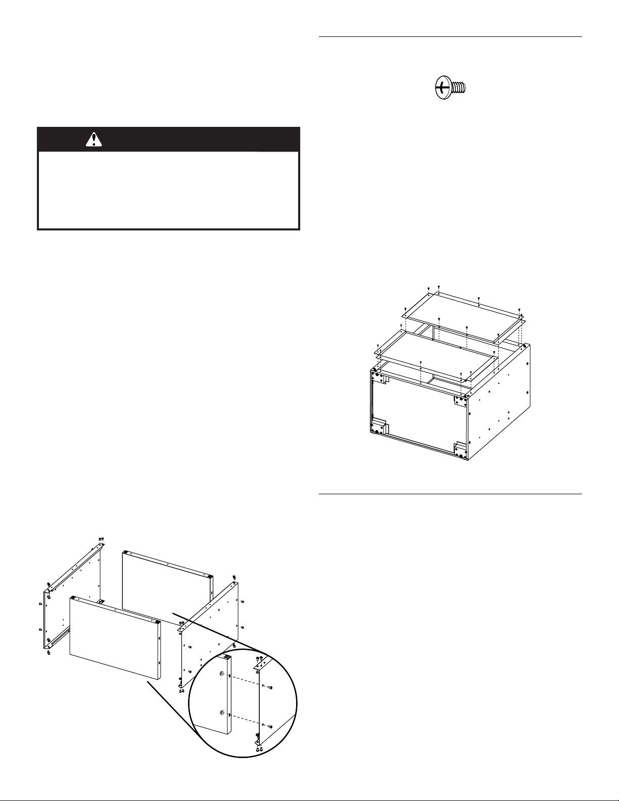
Assemble Cabinet
F1 F2
F1
⁵⁄₁₆
" Allen-head bolt (24)
⁵⁄₁₆
" Flange nut (24)
F2
Gather the required tools before starting installation.
3
Page 4

Tools Needed:
■ ¹⁄₂" Wrench
■ ³⁄₈" Wrench
■ ¹¹⁄₃₂" Wrench
Tools Supplied:
■ Allen wrench ■ Key
■ Phillips screwdriver
■ Pliers
■ Level
WARNING
Excessive Weight Hazard
Use two or more people to move, assemble or install
cabinet.
Failure to do so can result in back or other injury.
IMPORTANT:
■ Two people may be required to complete the assembly.
■ As you assemble the cabinet, make sure the edges with the
holes are facing up.
■ If you are assembling the cabinet on the floor, fasten the eight
front corner bolts, two at each corner, after you stand the cabinet
upright.
1. Place side panel (P1) on a flat, firm surface so that the edge with
the holes is facing up as shown.
2. Insert the cabinet top (P2) between the edges of side panel (P1).
NOTE: Make sure the edges with the holes are facing up.
3. Align the holes and attach the top (P2) to side panel (P1) using
Allen-head bolts (F1) and ⁵⁄₁₆"
tighten completely.
4. Position side panel (P3) so that the top (P2) is between the edges
of side panel (P3).
5. Align the holes and attach the top (P2) to the side (P3) using
Allen-head bolts (F1) and ⁵⁄₁₆"
tighten completely.
6. Insert cabinet bottom (P4) between the edges of side panels
(P1 and P3).
NOTE: Make sure the edges with the holes are facing up.
7. Align the holes and attach the bottom (P4) to the side panels
(P1 and P3) using Allen-head bolts (F1) and ⁵⁄₁₆"
for each side as shown. Do not tighten completely.
flange nuts (F2) as shown. Do not
flange nuts (F2) as shown. Do not
flange nuts (F2)
Attach Back Panels
F3b
F3b Phillips-head screw (16 - black)
1. Align lower back panel (P6) with the holes in the cabinet
bottom (P4). Using Phillips-head screws (F3b), attach back panel
(P6) to the bottom (P4) and sides (P1 and P3) as shown. Do not
tighten screws completely.
2. Align upper back panel (P5) with the holes in the cabinet top (P2).
Using Phillips-head screws (F3b), attach back panel (P5) to the
top (P2) and sides (P1 and P3) as shown. Do not tighten screws
completely.
NOTE: Upper back panel (P5) will slightly overlap lower back
panel (P6).
3. Using Phillips-head screws (F3b), attach the upper back panel
(P5) to the lower back panel (P6) as shown.
4. Completely tighten all back panel screws starting with the sides
and continuing with the top, middle, and bottom.
P5
P2
P6
P3
P1
P4
5. Using the Allen wrench (provided), completely tighten all the
cabinet bolts and nuts.
Install Leveling Legs or Casters
The Gladiator® Modular Cabinet is designed to be either stationary or
P1
P4
P3
P2
P2
P3
4
to roll on casters.
IMPORTANT: If you decide to install the casters on the cabinet, see
the installation instructions included with the caster kit (provided).
To install leveling legs:
1. Place the cabinet on its side.
Page 5

2. Screw a leveling leg (P7) into each of the four rivet nuts located at
A
A
the corners of the cabinet as shown.
P1
Install Doors
P7
P6
P4
A. Leveling legs
3. Stand the cabinet upright.
4. If you have not already, fasten the two bolts at each front corner,
of the cabinet frame. Completely tighten all the cabinet bolts and
nuts.
Install Shelves
F3b F4
F3b Phillips-head screw (8 - black) F4 Small flange nut (8)
IMPORTANT:
■ Install shelf (P8m) in the cabinet so that the long edge with
magnets is facing the cabinet front.
■ Use the pair of holes indicated to install shelf (P8m), so the doors
will lock.
■ Shelf (P8) may be installed using any of the other pairs of holes in
the cabinet sides.
1. Align the holes in the shelf with the pair of holes shown.
2. Using Phillips-head screws (F3b) and small flange nuts (F4) per
side, fasten shelf (P8m) to the cabinet sides (P1 and P3).
P2
P1
P3
A
P8m
F3
F3b Phillips-head screw (8 - black)
The door hinges are designed with keyhole slots at the top and
bottom so the door will hang on the cabinet while you are fastening
the screws.
1. Start Phillips-head screws (F3b) in both the top and bottom holes
on each side of the cabinet.
2. Hang the right-hand side door (P7) from the top and bottom
screws, and hand tighten.
3. Insert the middle two screws through the door hinge into the
cabinet and hand tighten.
P2
P8m
P8
P9
P4
A. Phillips-head screws (F3b)
4. Repeat steps 2 and 3 to attach the left-hand door (P8).
5. Align the doors and completely tighten the screws.
Complete the Assembly
1. Make sure there is a bolt or screw in each hole of the cabinet
frame.
2. Move the cabinet to its final location.
3. Place a level on the inside shelf, and if necessary, level the
cabinet by adjusting the height of the leveling legs (P7). Turn to
the left to raise or to the right to lower the leveling leg.
4. If the doors are not aligned, loosen all the screws attaching the
door hinge to the cabinet.
5. Adjust door to the desired height, and fully tighten the screws.
B
A. Holes for installing shelf
B. Slot in shelf for lock
3. Place shelf (P8) so that the holes in the ends are aligned with the
desired set of holes in the cabinet sides (P1 and P3).
4. Using Phillips-head screws (F3b) and small flange nuts (F4) per
side, fasten the shelf to the cabinet sides (P1 and P3).
ACCESSORIES
To order the accessories listed below or to inquire about other
available accessories call 1-866-342-4089 or contact your
authorized Gladiator brand dealer.
In Canada, call 1-800-807-6777.
VersaTop™ Work Surface
Order Part # GAVT18SPSX
5
Page 6

GLADIATOR® GARAGEWORKS
STEEL MODULAR GEARBOX CABINET WARRANTY
TEN YEAR LIMITED WARRANTY
For ten years from the date of purchase, when the Steel Modular GearBox Cabinet is used and maintained according to the instructions
attached to or furnished with the product, Gladiator
correct defects in materials or workmanship.
®
GarageWorks will pay for replacement or repair of the defective product or parts to
Gladiator® GarageWorks will not pay for:
1. Service calls to correct the installation of any Gladiator
®
GarageWorks products or to instruct you on how to use or install them.
2. Damage resulting from improper handling or shipping of products, or products damaged by accident, misuse, abuse, fire, flood,
improper installation, acts of God, neglect, corrosion, modification or mishandling.
3. Shipping or freight fees to deliver replacement products or to return defective products.
4. Repairs or replacement when your product is used in other than normal, single-family household use, such as a commercial
environment or handled in any way inconsistent with the installation instructions included with the product.
5. Cosmetic damage including scratches, dings, dents or cracks that do not affect the structural or functional capability of the
product.
6. Replacement parts or product for Gladiator
®
GarageWorks products operated outside the United States or Canada.
7. In Canada, travel or transportation expenses for customers who reside in remote areas.
8. Any labor costs during the limited warranty period.
9. Damage resulting from improper loading beyond the specified maximum weight capacity outlined in the assembly instructions
provided with the product, including overloading of hooks, baskets, shelves, cabinets, and other Gladiator
®
GarageWorks
accessories used with the product.
10. Surfaces damaged due to chemical interaction resulting in corrosion of paint or metal.
11. Replacement keys or locking mechanism.
12. Loss of product contents due to theft, fire, flood, accident or acts of God.
DISCLAIMER OF IMPLIED WARRANTIES; LIMITATION OF REMEDIES
IMPLIED WARRANTIES, INCLUDING TO THE EXTENT APPLICABLE WARRANTIES OF MERCHANTABILITY OR FITNESS FOR A
PARTICULAR PURPOSE, ARE EXCLUDED TO THE EXTENT LEGALLY PERMISSIBLE. ANY IMPLIED WARRANTIES THAT MAY BE
IMPOSED BY LAW ARE LIMITED TO ONE YEAR, OR THE SHORTEST PERIOD ALLOWED BY LAW. SOME STATES AND PROVINCES
DO NOT ALLOW LIMITATIONS OR EXCLUSIONS ON HOW LONG AN IMPLIED WARRANTY OF MERCHANTABILITY OR FITNESS
LASTS, SO THE ABOVE LIMITATIONS OR EXCLUSIONS MAY NOT APPLY TO YOU. THIS WARRANTY GIVES YOU SPECIFIC LEGAL
RIGHTS, AND YOU MAY ALSO HAVE OTHER RIGHTS WHICH VARY FROM STATE TO STATE OR PROVINCE TO PROVINCE.
Outside the 50 United States and Canada, this warranty does not apply. Contact your authorized Gladiator® GarageWorks dealer to
determine if another warranty applies.
If you need service, call the Gladiator
®
GarageWorks Customer eXperience Center, 1-866-342-4089 (toll-free), from anywhere in the
U.S.A. In Canada, contact your Whirlpool Canada LP designated service company or call 1-800-807-6777.
In the United States, Gladiator
®
GarageWorks means Whirlpool Corporation, Benton Harbor, Michigan 49022. In Canada, Gladiator®
GarageWorks means Whirlpool Canada LP, Mississauga, ON L5N 0B7. 12/09
Keep this book and your sales slip together for future
reference. You must provide proof of purchase or installation
date for in-warranty service.
Write down the following information about your Steel Modular
GearBox Cabinet to better help you obtain assistance or service
if you ever need it. You will need to know your complete model
number and serial number. You can find this information on the
model and serial label located on the back of the product.
6
Dealer name____________________________________________________
Address ________________________________________________________
Phone number __________________________________________________
Model number __________________________________________________
Serial number __________________________________________________
Purchase date __________________________________________________
Page 7

SEGURIDAD DEL ARMARIO
Su seguridad y la seguridad de los demás es muy importante.
Hemos incluido muchos mensajes importantes de seguridad en este manual y en su electrodoméstico. Lea y obedezca siempre
todos los mensajes de seguridad.
Este es el símbolo de advertencia de seguridad.
Este símbolo le llama la atención sobre peligros potenciales que pueden ocasionar la muerte o una lesión a
usted y a los demás.
Todos los mensajes de seguridad irán a continuación del símbolo de advertencia de seguridad y de la palabra
“PELIGRO” o “ADVERTENCIA”. Estas palabras significan:
PELIGRO
ADVERTENCIA
Todos los mensajes de seguridad le dirán el peligro potencial, le dirán cómo reducir las posibilidades de sufrir una lesión y lo que
puede suceder si no se siguen las instrucciones.
Si no sigue las instrucciones de inmediato, usted puede
morir o sufrir una lesión grave.
Si no sigue las instrucciones, usted puede morir o sufrir
una lesión grave.
7
Page 8

P1
PIEZAS
P2
P5
P8m
P6
P8
P9
P4
P7
F1 F2 F3b F4
P10
INSTRUCCIONES DE ENSAMBLAJE
P3
Requisitos de uso del armario
■ Diseñado para usarse en un garage.
■ El límite de peso máximo es de 45 lbs (20 kg) para cada estante.
■ El límite de peso máximo es de 300 lbs (136 kg) para el armario.
Desempaque las piezas del armario
1. Quite y verifique el contenido. Se incluye una llave Allen, una
llave y las piezas y sujetadores que se muestran en “Piezas”.
2. Deshágase de todos los materiales de embalaje o recíclelos.
8
Ensamble el armario
F1 F2
F1 Perno Allen de
F2 Tuerca de reborde de
Reúna las herramientas necesarias antes de comenzar la instalación.
⁵⁄₁₆
" (24)
⁵⁄₁₆
" (24)
Page 9
Herramientas necesarias:
■ Llave de tuercas de ¹⁄₂"
■ Llave de tuercas de ³⁄₈"
■ Llave de tuercas de ¹¹⁄₃₂"
Herramientas suministradas:
■ Llave Allen ■ Llave
■ Destornillador Phillips
■ Pinzas
■ Nivel
Sujete los paneles posteriores
F3b
F3b Tornillo Phillips (16 - negro)
ADVERTENCIA
Peligro de Peso Excesivo
Use dos o más personas para mover, ensamblar o
instalar el armario.
No seguir esta instrucción puede ocasionar una
lesión en la espalda u otro tipo de lesiones.
IMPORTANTE:
■ Tal vez se necesiten dos personas para completar el ensamble.
■ A medida que ensambla el armario, asegúrese de que los bordes
con orificios estén mirando hacia arriba.
■ Si usted está ensamblando el armario sobre el piso, ajuste los
ocho pernos frontales de la esquina, dos en cada esquina,
después de poner el armario en posición vertical.
1. Coloque el panel lateral (P1) sobre una superficie plana y firme
de manera que el extremo con orificios quede mirando hacia
arriba, como se muestra.
2. Inserte la parte superior del armario (P2) entre los extremos del
panel lateral (P1).
NOTA: Asegúrese de que los bordes con orificios estén mirando
hacia arriba.
3. Alinee los orificios y sujete la parte superior (P2) al panel
lateral (P1) usando pernos Allen (F1) y tuercas de reborde de
⁵⁄₁₆" (F2), como se muestra. No los apriete completamente.
4. Coloque el panel lateral (P3) de manera que la parte superior del
armario (P2) quede entre los extremos del panel lateral (P3).
5. Alinee los orificios y sujete la parte superior (P2) a la parte
lateral (P3) usando pernos Allen (F1) y tuercas de reborde de
⁵⁄₁₆" (F2), como se muestra. No los apriete completamente.
6. Inserte la parte inferior del armario (P4) entre los bordes de los
paneles laterales (P1 y P3).
NOTA: Asegúrese de que los bordes con orificios estén mirando
hacia arriba.
7. Alinee los orificios y fije la parte inferior (P4) a los paneles
laterales (P1 y P3) usando los pernos Allen (F1) y tuercas de
reborde de ⁵⁄₁₆" (F2) para cada lado, como se muestra. No los
apriete completamente.
P1
P4
1. Alinee el panel posterior inferior (P6) con los orificios en la parte
inferior del armario (P4). Sujete el panel posterior (P6) a la parte
inferior (P4) y a los lados (P1 y P3) usando tornillos Phillips (F3b),
como se muestra. No atornille completamente los tornillos.
2. Alinee el panel posterior superior (P5) con los orificios en la parte
superior del armario (P2). Sujete el panel posterior (P5) a la parte
superior (P2) y los lados (P1 y P3) usando tornillos Phillips (F3b),
como se muestra. No apriete completamente los tornillos.
NOTA: El panel posterior superior (P5) va a sobrepasar
ligeramente el panel posterior inferior (P6).
3. Sujete el panel posterior superior (P5) al panel posterior inferior
(P6) usando tornillos Phillips (F3b), como se muestra.
4. Apriete por completo todos los tornillos del panel posterior,
comenzando por los lados y siguiendo por la parte superior, del
medio e inferior.
P5
P2
P6
P3
P1
P4
5. Apriete por completo todos los pernos y tuercas del armario con
la llave Allen (provista).
Instalación de las patas
niveladoras o ruedecillas
El armario modular Gladiator® ha sido diseñado para estar fijo o para
rodar sobre ruedecillas.
IMPORTANTE: Si decide instalar las ruedecillas en el armario, vea
las instrucciones de instalación incluidas con el juego de ruedecillas
(provisto).
Para instalar las patas niveladoras:
1. Coloque el armario de costado.
P2
P2
P3
P3
9
Page 10

2. Atornille una pata niveladora (P7) en cada una de las cuatro
A
A
tuercas con remache que están ubicadas en las esquinas del
armario, como se muestra.
P1
Instalación de las puertas
P7
P6
P4
A. Patas niveladoras
3. Coloque el armario en posición vertical.
4. Si aún no lo ha hecho, asegure los dos pernos que están en la
esquina frontal del marco del armario. Apriete por completo
todos los pernos y las tuercas del armario.
Instalación de los estantes
F3b F4
F3b Tornillo Phillips (8 - negro) F4 Tuerca de reborde
pequeña (8)
IMPORTANTE:
■ Instale el estante (P8m) en el armario de manera que el borde
largo con imanes esté mirando hacia el frente del armario.
■ Use el par de orificios indicado para instalar el estante (P8m) de
manera que se aseguren las puertas.
■ Puede instalarse el estante (P8) usando cualquiera de los otros
pares de orificios a los lados del armario.
1. Alinee los orificios del estante con el par de orificios que se
muestran.
2. Fije el estante (P8m) a los lados del armario (P1 y P3) usando
tornillos Phillips (F3b) y tuercas de reborde pequeñas (F4) por
cada lado.
P2
P1
F3b
F3b Tornillo Phillips (8 - negro)
Las bisagras de la puerta se han diseñado con bocallaves en la parte
superior e inferior, de modo que la puerta cuelgue en el armario
mientras que usted coloca los tornillos.
1. Empiece colocando tornillos Phillips (F3b) en los orificios en la
parte superior e inferior, a cada lado del armario.
2. Cuelgue la puerta del lado derecho (P7) de los tornillos
superiores e inferiores y apriételos a mano.
3. Inserte los dos tornillos del medio en el armario, a través de la
bisagra de la puerta, y apriételos a mano.
P2
P8m
P8
P9
P4
A. Tornillos Phillips (F3b)
4. Repita los pasos 2 y 3 para fijar la puerta izquierda (P8).
5. Alinee las puertas y apriete los tornillos por completo.
Complete el ensamblaje
1. Asegúrese de que haya un perno o un tornillo en cada orificio del
marco del armario.
2. Mueva el armario a su ubicación final.
3. Coloque un nivel en la parte interior del estante y, si es necesario,
nivele el armario ajustando la altura de las patas niveladoras (P7).
Gire hacia la izquierda para levantar la pata niveladora o hacia la
derecha para bajarla.
4. Si las puertas no están alineadas, afloje todos los tornillos que
sujetan la bisagra de la puerta al armario.
5. Ajuste la puerta a la altura deseada y apriete completamente los
tornillos.
P3
A
A. Orificios para instalar el estante
B. Ranura en el estante para la cerradura
3. Coloque el estante (P8) de manera que los orificios de los
extremos estén alineados con el conjunto deseado de orificios a
los lados del armario (P1 y P3).
4. Fije el estante a los lados del armario (P1 y P3) usando dos
tornillos Phillips (F3b) y dos tuercas de reborde pequeñas (F4)
por cada lado.
P8m
B
10
ACCESORIOS
Para pedir los accesorios que se indican a continuación, o para
averiguar acerca de otros accesorios disponibles, llame al
1-866-342-4089 o póngase en contacto con su distribuidor
autorizado para la marca Gladiator. En Canadá, llame
al 1-800-807-6777.
Superficie de trabajo VersaTop™
Pida la pieza número GAVT18SPSX
Page 11

GARANTÍA DEL ARMARIO MODULAR DE ACERO PARA
HERRAMIENTAS GLADIATOR
GARANTÍA LIMITADA DE DIEZ AÑOS
Durante diez años a partir de la fecha de compra, siempre y cuando se le dé al armario modular de acero para herramientas un uso y
mantenimiento de conformidad con las instrucciones adjuntas o provistas con el producto, Gladiator
reemplazo o la reparación del producto o las piezas defectuosos para corregir defectos en los materiales o en la mano de obra.
®
GARAGEWORKS
®
GarageWorks pagará por el
Gladiator® GarageWorks no pagará por:
1. Visitas de servicio técnico para corregir la instalación de cualquier producto de Gladiator
®
GarageWorks o para enseñarle a usarlo o
instalarlo.
2. Daños causados por mal manejo o envío inapropiado de productos o productos dañados por accidente, uso indebido, abuso,
incendio, inundación, instalación incorrecta, actos fortuitos, negligencia, corrosión, modificación o maltrato.
3. Costo de envío o flete para entregar productos de repuesto o para devolver productos defectuosos.
4. Reparaciones o reemplazo cuando su producto ha sido empleado para fines ajenos al uso doméstico normal en la casa de una
familia, tal como uso en un lugar comercial, o se haya tratado de alguna manera en contra de las instrucciones de instalación
incluidas con el producto.
5. Daños estéticos incluyendo rayaduras, golpes, abolladuras o rajaduras que no afecten la capacidad estructural o de
funcionamiento del producto.
6. Piezas o productos de repuesto de productos Gladiator
®
GarageWorks que se empleen fuera de los Estados Unidos o Canadá.
7. En Canadá, gastos de viaje o de transporte para clientes que residen en zonas distantes.
8. Cualquier gasto de mano de obra durante el período de la garantía limitada.
9. Daños causados por la carga indebida que exceda del peso máximo especificado que se detalla en las instrucciones de
ensamblaje provistas con el producto, incluyendo la sobrecarga de ganchos, canastas, estantes, armarios y otros accesorios de
Gladiator
®
GarageWorks usados con este producto.
10. Superficies dañadas debido a la interacción química que dé como resultado la corrosión de pintura o de metal.
11. Mecanismo de traba o llaves de reemplazo.
12. Pérdida del contenido del producto debida a robo, incendio, inundación, accidente o actos fortuitos.
EXCLUSIÓN DE GARANTÍAS IMPLÍCITAS; LIMITACIÓN DE RECURSOS
LAS GARANTÍAS IMPLÍCITAS, INCLUYENDO EN LA MEDIDA QUE CORRESPONDA LAS GARANTÍAS DE COMERCIABILIDAD O DE
CAPACIDAD PARA UN PROPÓSITO PARTICULAR, SON EXCLUIDAS EN LA MEDIDA EN QUE SEA LEGALMENTE PERMISIBLE. TODA
GARANTÍA QUE SEA IMPUESTA POR LEY SERÁ LIMITADA A UN AÑO O AL PERÍODO MÁS CORTO PERMITIDO POR LEY. ALGUNOS
ESTADOS Y PROVINCIAS NO PERMITEN LAS LIMITACIONES O EXCLUSIONES ACERCA DE CUÁNTO DEBE DURAR UNA
GARANTÍA IMPLÍCITA DE COMERCIABILIDAD O CAPACIDAD, DE MODO QUE LAS LIMITACIONES O EXCLUSIONES ARRIBA
MENCIONADAS PUEDEN NO APLICARSE EN SU CASO. ESTA GARANTÍA LE OTORGA DERECHOS LEGALES ESPECÍFICOS Y ES
POSIBLE QUE USTED TENGA TAMBIÉN OTROS DERECHOS QUE PUEDEN VARIAR DE UN ESTADO A OTRO O DE UNA PROVINCIA
A OTRA.
Esta garantía no tiene vigor fuera de los cincuenta Estados Unidos y Canadá. Póngase en contacto con el distribuidor autorizado de
Gladiator
Si necesita servicio, llame al Centro para la eXperiencia del cliente de Gladiator
®
GarageWorks para determinar si corresponde otra garantía.
®
GarageWorks, 1-866-342-4089 (gratuito), desde
cualquier lugar de los EE.UU. En Canadá, póngase en contacto con su compañía de servicio designada de Whirlpool Canada LP o
llame al 1-800-807-6777.
En los Estados Unidos, Gladiator
®
GarageWorks significa Whirlpool Corporation, Benton Harbor, Michigan 49022. En Canadá,
Gladiator® GarageWorks significa Whirlpool Canada LP, Mississauga, ON L5N 0B7. 1/10
Guarde este libro y su comprobante de compra juntos para
referencia futura. Usted deberá proporcionar el comprobante
de la compra o una fecha de instalación para obtener
servicio bajo la garantía.
Escriba la siguiente información acerca del armario modular de
acero para herramientas para ayudarle mejor a obtener
asistencia o servicio técnico si alguna vez llegara a necesitarlo.
Deberá tener a mano el número completo del modelo y de la
serie. Usted puede encontrar esta información en la etiqueta con
el número de modelo y de serie que está ubicada en la parte
posterior del producto.
Nombre del distribuidor _________________________________________
Dirección_______________________________________________________
Número de teléfono _____________________________________________
Número de modelo _____________________________________________
Número de serie ________________________________________________
Fecha de compra _______________________________________________
11
Page 12

SÉCURITÉ DE L’ARMOIRE
Votre sécurité et celle des autres est très importante.
Nous donnons de nombreux messages de sécurité importants dans ce manuel et sur votre appareil ménager. Assurez-vous de
toujours lire tous les messages de sécurité et de vous y conformer.
Voici le symbole d’alerte de sécurité.
Ce symbole d’alerte de sécurité vous signale les dangers potentiels de décès et de blessures graves à vous
et à d’autres.
Tous les messages de sécurité suivront le symbole d’alerte de sécurité et le mot “DANGER” ou
“AVERTISSEMENT”. Ces mots signifient :
Risque possible de décès ou de blessure grave si vous ne
DANGER
AVERTISSEMENT
Tous les messages de sécurité vous diront quel est le danger potentiel et vous disent comment réduire le risque de blessure et
ce qui peut se produire en cas de non-respect des instructions.
suivez pas immédiatement les instructions.
Risque possible de décès ou de blessure grave si vous
ne suivez pas les instructions.
12
Page 13

P1
PIÈCES
P2
P5
P8m
P6
P8
P9
P4
P10
P7
F1 F2 F3b F4
INSTRUCTIONS D'ASSEMBLAGE
P3
Spécifications d'utilisation de l'armoire
■ Le produit est conçu pour l'utilisation dans un garage.
■ Charge maximale de 45 lb (20 kg) pour chaque étagère.
■ Charge maximale de 300 lb (136 kg) pour l'armoire.
Déballage des composants de l'armoire
1. Retirer le contenu; vérifier la présence de tous les composants.
Le contenu inclut une clé Allen, une clé de serrure, ainsi que
toutes les pièces et attaches illustrées dans la section “Pièces”.
2. Jeter/recycler tous les matériaux d'emballage.
Assemblage de l'armoire
F1 F2
F1 Vis Allen de
F2 Écrou à embase de
Rassembler les outils nécessaires avant de commencer l'installation.
⁵⁄₁₆
" (24)
⁵⁄₁₆
" (24)
13
Page 14

Outillage nécessaire :
■ Clé de ¹⁄₂"
■ Clé de ³⁄₈"
■ Clé de ¹¹⁄₃₂"
Outils fournis :
■ Clé Allen ■ Clé
■ Tournevis Phillips
■ Pince
■ Niveau
AVERTISSEMENT
Risque du poids excessif
Utiliser deux ou plus de personnes pour déplacer,
assembler, ou installer l’armoire.
Le non-respect de cette instruction peut causer
une blessure au dos ou d'autre blessure.
IMPORTANT :
■ La participation de deux personnes peut être nécessaire pour
l'assemblage.
■ Lors de l'assemblage de l'armoire, placer vers le haut les rives
comportant les trous.
■ Si vous assemblez l’armoire sur le plancher, serrer les huit
boulons de coin, deux à chaque angle, après avoir placé
l’armoire en position verticale.
1. Placer un panneau latéral (P1) sur une surface ferme plane; la
rive comportant des trous doit être orientée vers le haut.
2. Insérer le panneau supérieur (P2) entre les rives du panneau
latéral (P1).
REMARQUE : Les rives comportant des trous doivent être
orientées vers le haut.
3. Aligner les trous; connecter le panneau du sommet (P2) avec le
panneau latéral (P1) - utiliser les vis Allen (F1) et les écrous à
embase de ⁵⁄₁₆" (F2) - voir l'illustration. Ne pas serrer
complètement.
4. Positionner le panneau latéral (P3); le panneau supérieur (P2) doit
se trouver entre les rives du panneau latéral (P3).
5. Aligner les trous; connecter le panneau du sommet (P2) avec le
panneau latéral (P3) - utiliser les vis Allen (F1) et les écrous à
embase de ⁵⁄₁₆" (F2) - voir l'illustration. Ne pas serrer
complètement.
6. Insérer le bas de l'armoire (P4) entre les rives des panneaux
latéraux (P1 et P3).
REMARQUE : Les rives comportant des trous doivent être
orientées vers le haut.
7. Aligner les trous; connecter le panneau du bas (P4) avec les
panneaux latéraux (P1 et P3) - utiliser les vis Allen (F1) et les
écrous à embase de ⁵⁄₁₆" (F2) pour chaque côté - voir
l’illustration. Ne pas serrer complètement.
P1
P4
Fixation des panneaux arrière
F3b
F3b Vis Phillips (16 - noires)
1. Aligner le panneau inférieur arrière (P6) avec les trous du bas de
l’armoire (P4). À l’aide des vis Phillips (F3b), fixer le panneau
arrière (P6) sur le panneau du bas (P4) et les panneaux latéraux
(P1 et P3) tel qu’illustré. Ne pas complètement serrer les vis.
2. Aligner le panneau arrière (P5) avec les trous du sommet (P2).
Utiliser les vis Phillips (F3b) pour assujettir le panneau arrière (P5)
avec le panneau supérieur (P2) et les panneaux latéraux (P1 et
P3) - voir l'illustration. Ne pas complètement serrer les vis.
REMARQUE : Le panneau arrière (P5) chevauchera légèrement
le panneau arrière (P6).
3. Utiliser les vis Phillips (F3b) pour assujettir le panneau arrière
supérieur (P5) avec le panneau arrière inférieur (P6) - voir
l'illustration.
P5
P2
P6
P3
P1
P4
4. Serrer complètement toutes les vis du panneau arrière -
commencer par les côtés et poursuivre avec le sommet, le milieu
de l'armoire et le fond.
5. Utiliser la clé Allen (fournie) pour serrer complètement tous les
boulons et écrous de l’armoire.
Installation des pieds de réglage de
l'aplomb ou des roulettes
L’armoire à outils modulaire Gladiator® peut être utilisée comme
armoire stationnaire ou roulante.
IMPORTANT : Si l’on décide d'installer les roulettes sur l'armoire,
voir les instructions d'installation fournies avec le kit de roulettes.
Installation des pieds de nivellement :
1. Placer l'armoire en appui sur un côté.
14
P2
P2
P3
P3
Page 15

2. Visser un pied de réglage de l'aplomb (P7) dans chacun des
A
A
quatre écrous situés dans les angles de l'armoire - voir
l'illustration.
P1
Installation des portes
P7
P6
P4
A. Pieds de réglage de l'aplomb
3. Placer l'armoire à la verticale.
4. Si ce n’est pas déjà effectué, serrer les deux boulons de chaque
angle à l’avant du cadre de l’armoire. Serrer complètement tous
les boulons et écrous de l’armoire.
Installation des étagères
F3b F4
F3b Vis Phillips (8 - noires) F4 Petit écrou à embase (8)
IMPORTANT :
■ Installer l’étagère (P8m) dans l’armoire de façon à ce que la rive
longue comportant l’aimant soit orientée vers l’avant de
l’armoire.
■ Utiliser les deux trous indiqués pour installer l’étagère (P8m) de
façon à ce que les portes puissent se verrouiller.
■ Pour l’installation de l’étagère (P8), on peut utiliser n’importe
lesquelles des autres paires de trous dans les côtés de l’armoire.
1. Aligner les trous sur l’étagère avec les trous illustrés.
2. Utiliser les vis Phillips (F3b) et petits écrous à embase (F4) sur
chaque côté pour assujettir l’étagère (P8m) sur les panneaux
latéraux (P1 et P3).
P2
P1
F3b
F3b Vis Phillips (8 - noires)
Les charnières de porte sont conçues avec les encoches en forme
de trous de serrure en haut et en bas de façon à ce que la porte soit
suspendue à l'armoire pendant que l'on serre les vis.
1. Engager les vis Phillips (F3b) dans les trous supérieurs et
inférieurs de chaque côté de l'armoire.
2. Suspendre la porte de droite (P7) aux vis supérieures et
inférieures puis serrer à la main.
3. Insérer les deux vis du milieu dans la charnière de porte, dans
l'armoire, puis serrer à la main.
P2
P8m
P8
P9
P4
4. Répéter les étapes 2 et 3 pour installer la porte de gauche (P8).
5. Aligner les portes et serrer complètement les vis.
Fin de l'assemblage
1. S’assurer qu’il y a un boulon ou une vis dans chaque trou du
cadre de l’armoire.
2. Déplacer l'armoire jusqu'à son emplacement d'installation final.
3. Placer un niveau sur l'étagère interne; si nécessaire, ajuster la
hauteur des pieds de réglage de l'aplomb (P7) pour établir
l'aplomb de l'armoire (rotation vers la gauche pour soulèvement
ou rotation vers la droite pour abaissement).
4. Si les portes ne sont pas alignées, desserrer les vis fixant la
charnière sur l'armoire.
5. Ajuster la position de la porte à la hauteur désirée et resserrer
complètement les vis.
P3
A
A. Trous pour installation de l'étagère
B. Rainure dans l'étagère
3. Placer l'étagère (P8) de manière à ce que les trous aux extrémités
soient alignés avec les trous de fixation choisis dans les
panneaux latéraux de l'armoire (P1 et P3).
4. Utiliser les vis Phillips (F3b) et petits écrous à embase (F4) de
chaque côté pour assujettir l'étagère sur les panneaux
latéraux (P1 et P3).
P8m
B
ACCESSOIRES
Pour commander les accessoires énumérés ci-dessous ou faire une
demande concernant d’autres accessoires disponibles, appeler au
1-866-342-4089 ou contacter un vendeur autorisé de produits
Gladiator. Au Canada, composer le 1-800-807-6777.
Surface de travail VersaTop™
Commander la pièce n° GAVT18SPSX
15
Page 16

GARANTIE DE L'ARMOIRE À OUTILS MODULAIRE EN ACIER DE
GLADIATOR
GARANTIE LIMITÉE DE DIX ANS
Pendant dix ans à compter de la date d'achat, lorsque l'armoire à outils modulaire en acier est utilisée et entretenue conformément aux
instructions jointes à ou fournies avec le produit, Gladiator
pièces défectueux pour corriger les vices de matériaux ou de fabrication.
®
GARAGEWORKS
®
GarageWorks paiera pour la réparation ou le remplacement du produit ou
Gladiator® GarageWorks ne paiera pas pour :
1. Les appels de service pour rectifier l'installation de tout produit Gladiator
®
GarageWorks ou pour expliquer comment l'utiliser ou
l'installer.
2. Les dommages causés par une manipulation ou une expédition des produits incorrecte, ou les produits endommagés par accident,
mésusage, abus, incendie, inondation, installation incorrecte, actes de Dieu, négligence, corrosion, modification ou mauvaise
manipulation.
3. Les frais d'expédition ou de transport pour livrer des produits de rechange ou retourner des produits défectueux.
4. Des réparations ou des remplacements lorsque le produit est utilisé autrement que pour une utilisation normale, unifamiliale,
comme dans un environnement commercial ou manipulé d'une façon non conforme aux instructions d'installation fournies avec le
produit.
5. Les défauts d'apparence - éraflures, traces de choc ou fissures - n'affectant pas la fonctionnalité ou la résistance structurale du
produit.
6. Les pièces ou le produit de rechange pour les produits Gladiator
®
GarageWorks qui sont utilisés en dehors des États-Unis ou du
Canada.
7. Au Canada, les frais de déplacement ou de transport pour les clients qui habitent dans des régions éloignées.
8. Tous les frais de main-d'œuvre encourus au cours de la période de garantie limitée.
9. Les dommages causés par un chargement incorrect au-delà de la capacité de poids maximum spécifiée dans les instructions
d'assemblage fournies avec le produit, y compris la surcharge de crochets, paniers, étagères, caisses et autres accessoires
Gladiator
®
GarageWorks utilisés avec le produit.
10. Les surfaces endommagées par une interaction chimique causée par la corrosion de la peinture ou du métal.
11. Clés ou mécanisme de verrouillage de rechange.
12. Perte du contenu du produit due à vol, incendie, inondation, accident ou catastrophe naturelle.
CLAUSE D'EXONÉRATION DE RESPONSABILITÉ AU TITRE DES GARANTIES IMPLICITES; LIMITATION DES RECOURS
LES GARANTIES IMPLICITES, Y COMPRIS LES GARANTIES PROLONGÉES APPLICABLES DE QUALITÉ MARCHANDE ET
D'APTITUDE À UN USAGE PARTICULIER, SONT EXCLUES DE LA PRÉSENTE GARANTIE, ET CE DANS LES LIMITES AUTORISÉES
PAR LA LOI. TOUTE GARANTIE IMPLICITE POUVANT ÊTRE IMPOSÉE PAR LA LOI EST LIMITÉE À UN AN, OU À LA PLUS COURTE
PÉRIODE AUTORISÉE PAR LA LOI. CERTAINES JURIDICTIONS NE PERMETTENT PAS LA LIMITATION OU L'EXCLUSION DE LA
DURÉE DE VALIDITÉ DES GARANTIES IMPLICITES DE QUALITÉ MARCHANDE OU D'APTITUDE À UN USAGE PARTICULIER; PAR
CONSÉQUENT LES LIMITATIONS OU EXCLUSIONS STIPULÉES DANS LES PRÉSENTES PEUVENT NE PAS VOUS ÊTRE
APPLICABLES. CETTE GARANTIE VOUS CONFÈRE DES DROITS JURIDIQUES SPÉCIFIQUES ET VOUS POUVEZ ÉGALEMENT
JOUIR D'AUTRES DROITS QUI PEUVENT VARIER D'UNE JURIDICTION À UNE AUTRE.
À l'extérieur du Canada et des 50 États des États-Unis, cette garantie ne s'applique pas. Contacter votre marchand Gladiator®
GarageWorks autorisé pour déterminer si une autre garantie s'applique.
Si vous avez besoin de service, appelez le Centre pour l'eXpérience de la clientèle de Gladiator
®
GarageWorks au 1-866-342-4089
(sans frais), de n'importe où aux É.-U. Au Canada, contactez votre compagnie de service désignée par Whirlpool Canada LP ou
composez le 1-800-807-6777.
Aux États-Unis, Gladiator
®
GarageWorks correspond à Whirlpool Corporation, Benton Harbor, Michigan 49022. Au Canada, Gladiator®
GarageWorks correspond à Whirlpool Canada LP, Mississauga, ON L5N 0B7. 12/09
Conservez ce manuel et votre reçu de vente pour référence
ultérieure. Pour l'entretien sous garantie, vous devez
présenter un document prouvant la date d'achat ou
d'installation.
Inscrivez les renseignements suivants au sujet de votre armoire à
outils modulaire en acier pour mieux vous aider à obtenir
assistance ou service en cas de besoin. Vous devrez connaître le
numéro de modèle et le numéro de série au complet. Vous
trouverez ces renseignements sur la plaque signalétique située à
l'arrière du produit.
W10309370A
© 2010 Whirlpool Corporation.
All rights reserved.
Todos los derechos reservados.
Tous droits réservés.
® Marque déposée/TM Marque de commerce de Whirlpool, U.S.A., emploi sous licence par Whirlpool Canada LP au Canada
® Registered Trademark/TM Trademark of Whirlpool, U.S.A., Whirlpool Canada LP Licensee in Canada
® Marca registrada/TM Marca de comercio de Whirlpool, U.S.A., usada bajo licencia de Whirlpool Canada LP en Canadá
Nom du marchand ______________________________________________
Adresse ________________________________________________________
Numéro de téléphone ___________________________________________
Numéro de modèle______________________________________________
Numéro de série ________________________________________________
Date d'achat____________________________________________________
Printed in China
Impreso en China
Imprimé en Chine
1/10
 Loading...