

Page 1
PEARCE-SIMPSON
DIVISION OF
GLADDING
CORP.
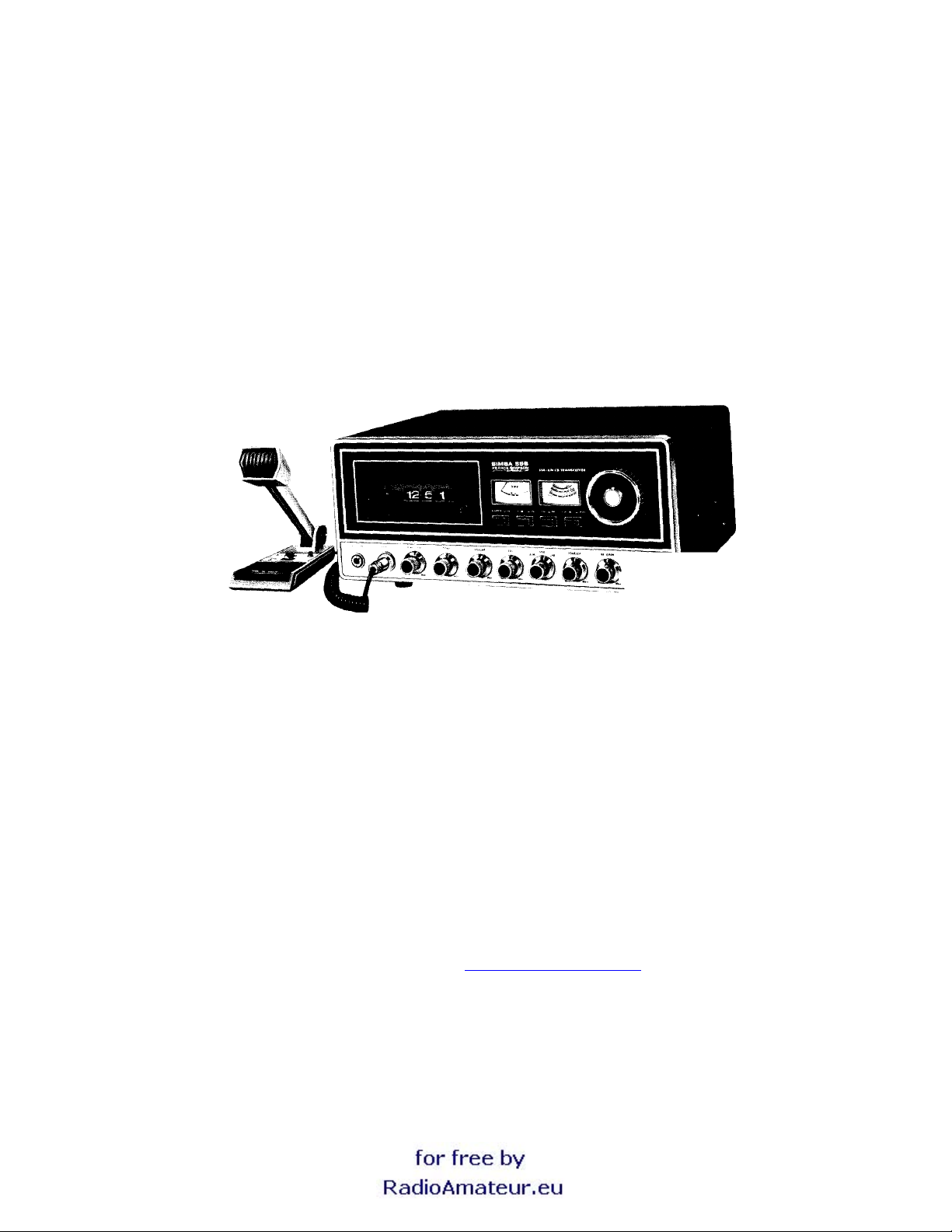
SIMBA SSB
PDF By Woody at
http://www.cbgazette.com
Page 2

SECTION 1
GENERAL INFORMATION
DESCRIPTION
Your new PEARCE-SIMPSON SIMBA SSB is an all transistorized, 23-channel Citizens Band SSB/AM Transceiver. This radio is ideally suited for base
and/or mobile operation from 115V AC or 12.6V DC power source, either posi t i ve or negat ive ground. A 12V DC power cord, a 117V AC power cord and
mounting cradle are included with your SIMBA SSB. To provide the crystal-controlled, 23-channel operation, PEARCE-SIMPSON utilizes an
all-transistor HetroSync circuit.
The receiver is a sensitive superheterodyne circuit featuring: Dual convers ion, low noise RF stage, slide-o-tune, adjustable squel ch, noise blanker,
external speaker jack, and inst antaneous selection of any of t he 23 crystal controlled channels .
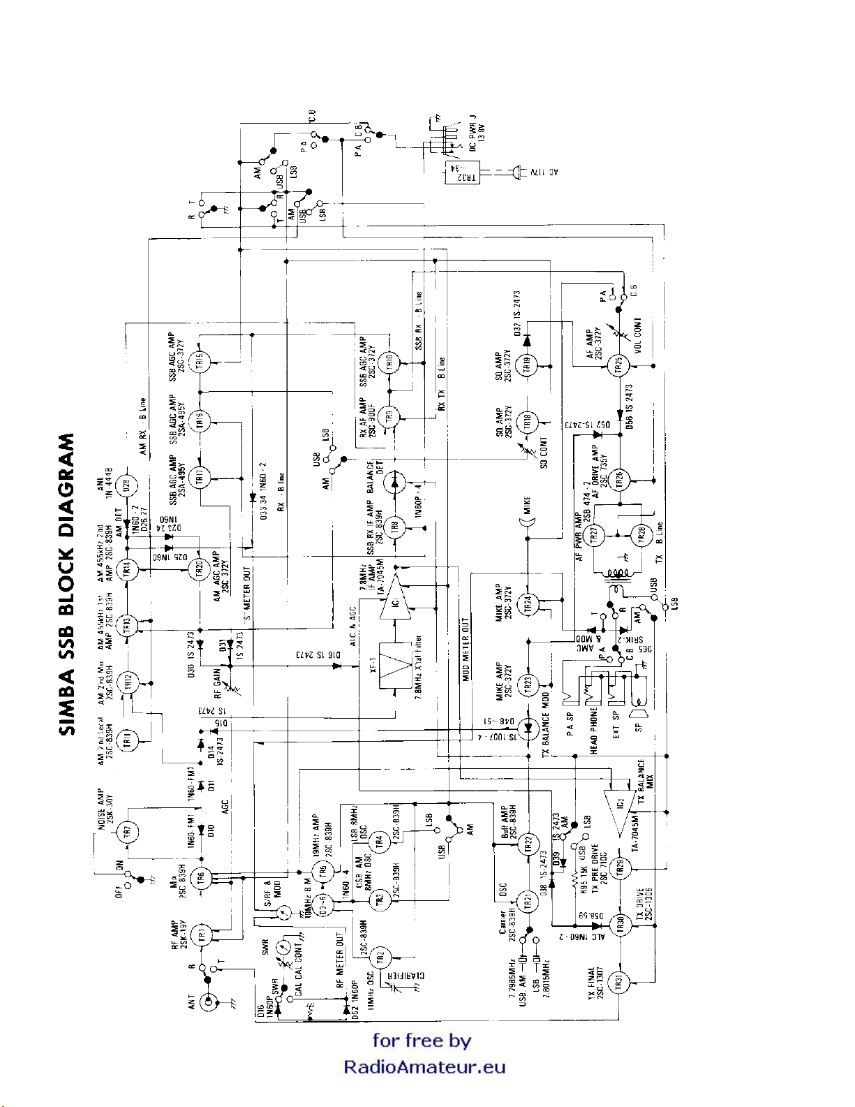
The transmitter section is designed around highly reliable silicon transist ors and the HetroSync circuit. This ci rcuit makes us e of the output of three
crystal -controIled oscillators which are m ixed together to produce the desired frequency. The transm itter final is a conservatively rated hi gh gain RF
power transistor.
Both transmitt er and receiver work on upper sideband or lower sideband.
SPECIFICATIONS
GENERAL:
Channels 23 Channels, Crystal-Cont rol l ed A M, Upper S i de Band or Lower Side Band
Frequency Range: 26.965 MHz. to 27.255 MHz.
Frequency Control: Synthesizer
Frequency Tolerance: 0.005%
Frequency Stability: 0.001 %
Operating Temperature Range: - 30*C to +50C
Primary Power: Input Volt age - 13.8 VDC (EIA Standard)/ 117 VAC
Antenna: 52-ohm Coaxial
Size: 15-1/16" W x6-1/4" H x 1 1-5/16" D
Weight: 16 Lbs. (approx.)
RECEIVER:
Sensitivity S.S.B.- Less than 0.2uV for 1 OdB S +N/N, A.M.- Less than 0.6uV for 10 dB S + N/N
Selectivity: S. S.B.6dB at 2.1 KHz., 60dB at 5.5kHz A.M. 6dB at 5KHz., 50dB at 20KHz
Spurious Rejection: 60dB minimum
Squelch Range: S.S.B. - A dj ustable from 0.5uV to 1,000uV A.M.- Adjustable from 0.51uV to 1,000uV -1
Page 3

1st IF Frequency S.S.B.- 7.8 MHz.
2nd I.F. Frequency A.M.- 455 KHz.
Noise Blanker Series gate type (uses F. E. T. )
Slide-O-Tune Range ±600Hz.
Audio Output Power 3.5 W
TRANSMITTER:
A.M.- 7.8 MHz.
Output Power S.S.B.-15 watts, p.e.p.
Modulation Capability A.M.- 100%
Spurious Harmonic Suppres sion 50dB minimum
Carrier Suppression S.S.B.- -40dB
Unwanted Sideband -40dB
Frequency Response S.S.B.- 350Hz. to 2,50OHz.
Output Impedance 50 ohms (unbalanced)
S.S.B. Filter 7.8MHz., Crystal lattice type,
Automatic Load Control Holds p.e.p. to I dB inc rease w/ 10 dB
A.M.- 4 watts
A.M.- 250Hz. to 3,00OHz
6dB at 2.1 KHz., 60dB at 5. 5KHz.
(increase in input)
FREQUENCIES AVAILABLE FOR CLASS D OPERATION
Channel MHz Channel MHz Channel MHz
1 26.965 9 27.065 * 17 27.165
2 26.975 10 27.075 * 18 27.175
3 26,985 1 1 27.085' 19 27.185
4 27.005 12 27.105* 20 27.205
5 27.015 13 27.1 15* 21 27.215
6 27.025 14 27.125* 22 27.225
7 27.035 15 27.135 23 27.255
8 27.055 16 27.155
*Channels available for communications between units of di f ferent stations (In accordance with FCC Part 95 .4 1 (d) (2))
WARNING
FCC Rules require that ALL transm itter adjustm ents, other than those s upplied by the manufact urer as front panel operating control s, be made by or
under the supervision of the holder of an FCC i ssued I st or 2nd class radi o operator's license.
Replacement or subst itution of cryst als, t ransis tors, regul ator diodes or any ot her part of a unique nat ure, with part s ot her than those rec omm ended by
the manufacturer m ay caus e violat ion of the t echni cal regul ations of Part 95 of the FCC Rul es or viol ation of t he Type A cc eptanc e requirement s of P art
2 of the Rules.
SECTION 2
INSTALLATION & INITIAL ADJUSTMENT
IMPORTANT
BEFORE DISCARDING ANY OF THE PACKING MATERIALS, EXAMINE THEM CAREFULLY FOR ITEMS YOU MAY HAVE
OVERLOOKED.
INSTALLING FIXED STATION
For fixed station operation, connect the AC power cable from the back of the unit to an AC outlet. Connect the antenna to the A ntenna
terminal on the back of the unit.
POWER CONNECTION
The SIMBA SSB is constructed to be used in vehicles using either negative or positive ground. The red power lead is to be connected
to the positive terminal of the battery. The black lead is the Negative Lead. If the existing wiring is used be sure that it is heavy enough
to prevent voltage drop to the radio. A good source of battery voltage is at the accessory connection on the ignition switch. Using this
as a power source insures the radio will be off when the ignition switch is in the off position and power with be supplied to the radio
when it is in the on or accessory position.
Page 4

ANTENNAS
BASE STATION
The directional beam type of antenna, used within its limitations, is the most effective type to deliver the strongest signals in a
particular direction. Gain in one direction is achieved by concentrating the radiated energy into a beam much as the reflector in a
flashlight. This effect is also true when the antenna is used for receiving, resulting in a stronger signal from the direction in which the
antenna is pointed and a weaker signal from all other direct. This type of antenna is very desirable for communications with stations in
a particular area. By the addition of rotator; you will able to beam your signals in any direction.
NOTE: The reference of antenna efficiency is a standard dipole antenna. For example, a beam antenna listed as having 6 db gain
means that it has 6 db of gain over a dipole (in the direction it is pointed). Each 3 db of gain is equal to doubling the power, therefore, 6
db would equal 4 times the power. A transmitter with 3 watts output would produce as strong a signal, with 6 db gain beam, as would a
12 watt transmitter feeding a dipole.
When 360-degree coverage is needed for communicating with several stations in different directions, the ground plane type of antenna
is very effective. This type affords excellent coverage for communicating with mobile stations which are constantly moving from one
area to another.
A modification of this antenna is the colinear ground plane which is actually a form of a beam. This beaming effects of the antenna are
in a vertical direction concentrating the energy nearer the ground and reducing the sky wave which would otherwise be lost.
For a base station, the whip antenna is the least desirable type and should be used only for very short range or when no other antenna
can be installed in the space available. If it is necessary that the antenna be installed on, or adjacent to the equipment, a -V" or rabbit
ear type is much more desirable.
POLARIZATION
For the most efficient communications, the antennas at each station should be mounted in the same plane, i.e. both should be vertical
or both should be horizontal. Since a major use of Citizens Bond Radio is communicating with mobile units which are equipped with
vertically mounted whip antenna, the vertical plane is preferred.
TYPICAL AUTOMOBILE INST ALLATION
MOBILE INSTALLATION
SIMBA SSB has been adjusted at the factory to
Your
52-ohm antennas available for mobile citizens band use.
For an automobile installation, a whip may be used with good efficiency because the automobile acts as a counterpoise and reduces
detuning effects. The mounting location also has a great effect on the efficiency.
The most efficient and practical installation is a full quarter wave whip mounted on the left rear deck of fender top midway between the
rear window and bumper.
The so-called "short whip" is a less efficient antenna because the radiation area is reduced. However, full use of its capability may be
achieved since a shorter antenna may be mounted in a more advantageous position on a automobile, such as in the middle of the top.
There are also newer mobile antennas on the market which are made to replace the entertainment radio antenna and are similar in
appearance.
These antennas serve three purposes: AM and FM entertainment broadcast reception and Citizens Band transmission and reception.
For a marine installation, the full-length quarter wave whip antenna is very efficient, however, it requires radials which make it hard to
mount in small boats. Another excellent antenna is the coaxial sleeve type which requires no radial. A similar antenna is the
centerloaded 1/ 2 wave which is about the same as the full length 1/4 wave whip and it requires no radials. Care must be used when
choosing one of the shortened type antennas as considerable variation in efficiency will be found between the various makes and
models. As a general rule, avoid those with short radiating elements because the greater the radiating area, the stronger the radiated
signal will be.
Your PEARCE-SIMPSON dealer is prepared to offer advice and will help you choose the most desirable antenna for your needs.
give optimum performance using a 52-ohm antenna. There are a number of
Page 5

TRANSMISSION LINE
To connect an antenna to the transceiver, a 52-ohm coaxial transmission line is required. [See Figure 1 for assembling connector to
RG-58/U coaxial cable.]
INSTALLATION ADJUSTMENTS
The output circuit of the SIMBA SSB transmitter has been factory adjusted to operate into any good 52-ohm antenna. No attempt
should be made to tune the transmitter to the antenna. Instead, the antenna should be adjusted to present the lowest possible SWR
(Standing Wave Ratio). A very low SWR means that the antenna is operating at maximum efficiency and will also mean that it is
adjusted to 52 ohms. An improperly adjusted antenna causes standing waves to appear on the feed line. Since this feed line is a fixed
52 ohms, and cannot be adjusted, this mismatch appears at the transmitter. If the transmitter is adjusted to compensate for this
mismatch, both it and the antenna will no longer be operating at peak efficiency. Since the transmitter has already been adjusted for
52 ohms output and the coaxial feed line has a fixed 52-ohm value, the only remaining element to be adjusted to this value is the
antenna itself. When received, the antenna is probably cut as near as is possible to this value. The mounting location on the vehicle or
building and surrounding objects affect the antenna however, and requires that it be adjusted to compensate for them.
Many of the newer Citizens Band antennas provide means of adjusting them for lowest SWR. Instructions for doing so are included
with the antenna. For such antennas as the full quarter wave length whip, it is nec
essary to carefully vary the length until the lowest SWR is obtained. For The built-in SWR bridge is ideal for this type of adjustment.
The SIMBA SSB will work into an antenna system having an SWR as high as 3: 1. For best communications, you will want this figure
as near I : I as possible so that the antenna will be operating at its best efficiency.
NOISE SUPPRESSION
SIMBA SSB
The
vehicular installations, the noise suppression for the entertainment radio will be sufficient. Vehicles and boats not having this
suppression may require that it be installed. In most cases, installation of distributor suppressors and generator condensers will be
sufficient. In severe cases, the service of aqualified technician may be required. See your PEARCE-SIMPSON dealer for advice.
contains a automatic noise limiter on AM and noise blanker on AM and SSB, and input power filtering. In most
WARNING
Operation of this equipment requires a valid station license issued by the Federal Communications Commission. Do Not transmit with
your equipment until you have received your license. Illegal operation can result in severe penalties. Be certain that you have read Part
95 of the FCC Rules and Regulations before operating your station.
License applications are to be made on FCC Form 505 available from your nearest FCC field office. (A copy of this form is included
with your new transceiver.)
You are required to maintain a current copy of Part 95 of the FCC Rules as a part of your station records. Copies of Part 95 are
available from: Superintendent of Documents GPO Washington, DC, 20402, for a fee of $3.50.
Your station license is to be posted in accordance with paragraph 95.101 of the Rules and an executed Transmitter Identification Card
(FCC Form 452-C) is to be attached to each transmitter. (A copy of this form is included with your new transceiver.)
Page 6
SECTION 3
OPERATING INSTRUCTIONS
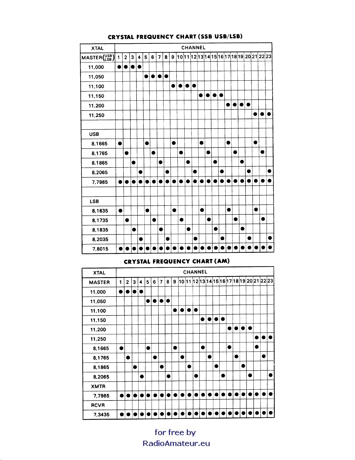
Your SIMBA SSB operates on sixty-nine different channels. There are 23 AM channels, 23 upper sideband and 23 lower sideband.
When in the AM mode, the SIMBA SSB will hear only signals being transmitted on double sideband with full carrier (AM). The unit may
also receive SSB signals when on the AM mode but you will not be able to understand them. When operating in either of the
modes,
strong AM signals may also be 'heard. It is recommended that you return to the AM mode if you wish to listen to these signals.
So that you will better understand the difference between AM, upperside band and lower sideband, a simplified explanation of their
characteristics is in order.
An AM signal consists of a carrier frequency and two sidebands, an upper and lower. Each sideband is an exact duplicate of the other.
An AM receiver, when it detects an AM signal, filters out the carrier so that you hear only the intelligence on the sideband. If you listen
to an AM signal when your receiver is in the sideband mode, the receiver will not reject the carrier frequency (unless the clarifier is
tuned exactly right) and a steady tone will be heard as well as the intelligence. Therefore, for best reception of AM, your mode selector
should be in the AM position.
When transmitting on single sideband, no carrier and only one sideband, either upper or lower, is being transmitted. W hen on AM,
your receiver cannot take just this one sideband and change it into usable intelligence. You can recognize a-sideband signal coming in
on AM by its fluttering characteristic and its unintelligible sound. A signal transmitted on upper sideband can only be properly heard by
a receiver tuned to the upper sideband.
When listening to a sideband signal on the proper mode, it may sound either too high pitched or too low pitched. The reason for this is
that your receiver may not be tuned to the exact same frequency as the transmitter it is listening to. For this reason, SIMBA SSB is
equipped with a Clarifier. By turning this Clarifier, you slightly change the frequency of both your transmitter and receivers (within legal
limits)
that reception will be in a normal tone.
so
SSB
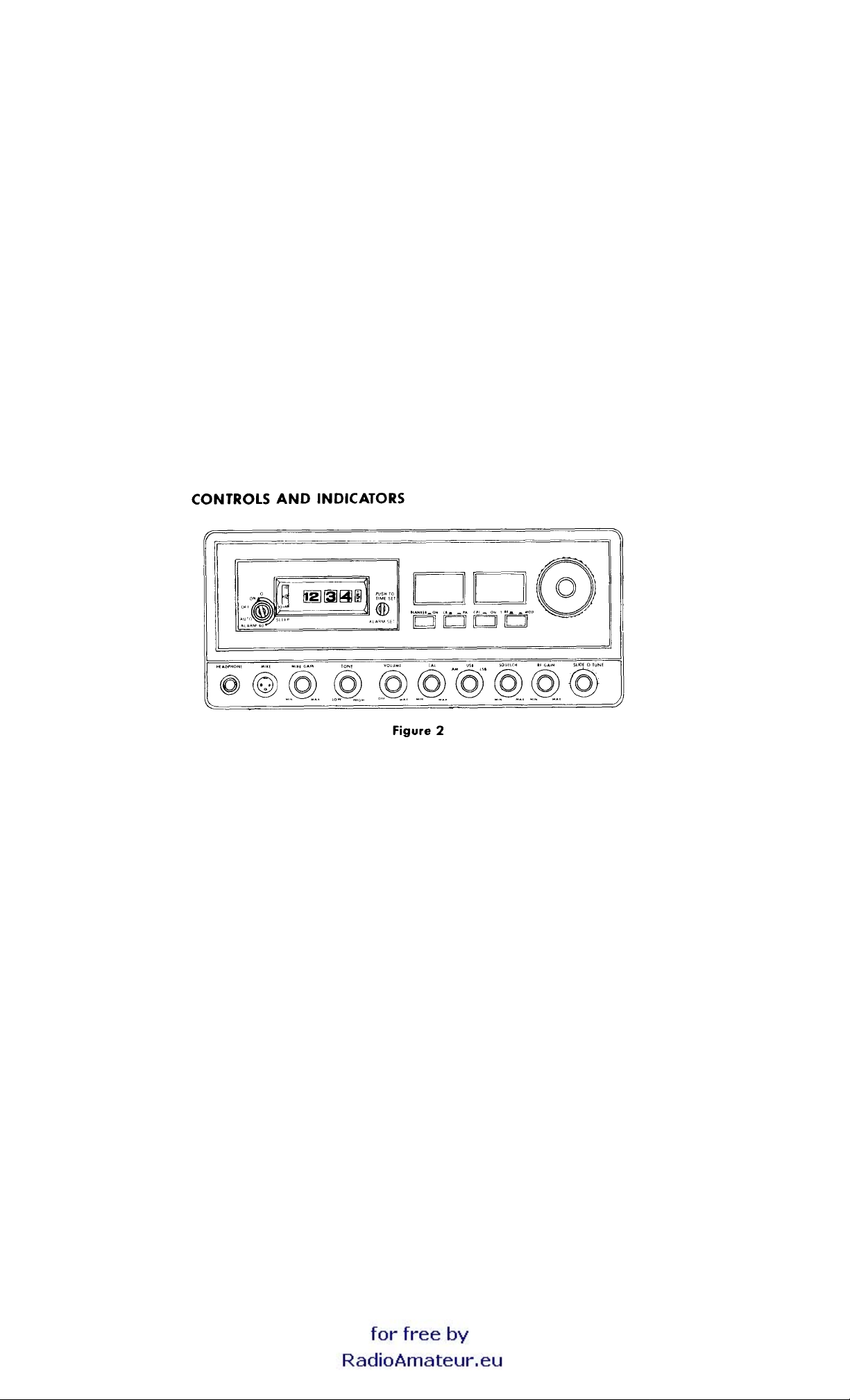
CHANNEL SELECTOR
The channel selector switch has 23 operating positions. This switch sets both transmit and receive frequencies simultaneously by
switching the proper crystals into the
MODE SELECTOR
This selector enables you to select either of SSB modes (upper sideband or lower sideband) or
PEARCE-SIMPSON
HetroSyncTM circuit for any of the 23 CB channels.
AM.
This switch changes both
transmitter and receiver simultaneously on each mode.
VOLUME CONTROL AND ON-OFF SWITCH
This control turns the power
RF GAIN CONTROL
ON
and OFF, and adjusts the loudness of received signal.
This control adjusts the strength of incoming signal. If too strong signal comes in, turn it counterclockwise. If you are listening to a
weak signal, turn it clockwise for a desired listening level.
SQUELCH CONTROL
The Squelch Control is used to silence background noise (atmospheric or man-made noise) in the absence of a received radio signal.
In the full counterclockwise position, the radio is unsquelched (no noise silencing at all). In the fully clockwise position, the unit is
squelched for very strong signals.
Page 7

SWR CALIBRATION CONTROL
This control is installed to adjust the calibration of SWR meter. Connect antenna, and turn on the power switch. Then, press the
microphone button and adjust CAL control so that the meter needle comes to "CAL" point. Push "CAL" button. Read the value on the
meter. The closer a I the value comes, the better matched antenna system will be.
NOISE BLANKER
The noise blanker is designed to reduce excessive noise such as electrical interference,
1
ignition noise, etc. To operate, simply push
in the button. To turn off push it again.
SLIDE-O-TUNE
This control allows you to vary the operating frequencies of both transmitter and receiver below and above the assigned frequency.
This may be used for optimum tuning of both SSB and AM signals.
PA-CB SWITCH
This switch is to select the operating mode of either CB or PA.
TONE CONTROL
This control is used to adjust for the best clarity and tone of received signal.
INDICATORS
I . Transmit Light: Comes on when microphone button is pressed and transmitter is on the air.
2. AM Mode Light: Comes on when Mode Switch is placed to AM position.
3. USB Mode Light: Comes on when Mode Switch is placed to USB position
4. LSB Mode Light: Comes on when Mode Switch is placed to LSB position.
5. SWR Meter: This is to adjust the calibration of the Meter and to read the SWR. To adjust the calibration, push "CAL"button, and
turn "CAL" control knob and make sure the meter needle comes to "CAL" point. To read the SWR, release the "CAL" button and read
the value on the 'meter. The closer to I the needle comes, the better matched antenna system will be.
6. S Meter: A change of one S unit indicates a change of 6 db in signal level. The metering circuit is calibrated so that for 100
microvolts, the S meter will read S9. To operate, set the "SWR/RF-MOD" switch to "S/RF" position.
7. RF Output Meter: This shows relative RF power when transmitting. To operate, set the "SWR/RF-MOD" switch to "S/RF" position.
8. MOD Meter: This shows relative transmitting Modulation Percentage. The meter needle fluctuates when unit is voice modulated.
To operate, set the "SWR/RF-MOD" switch to "MOD" position.
Page 8

SECTION 4
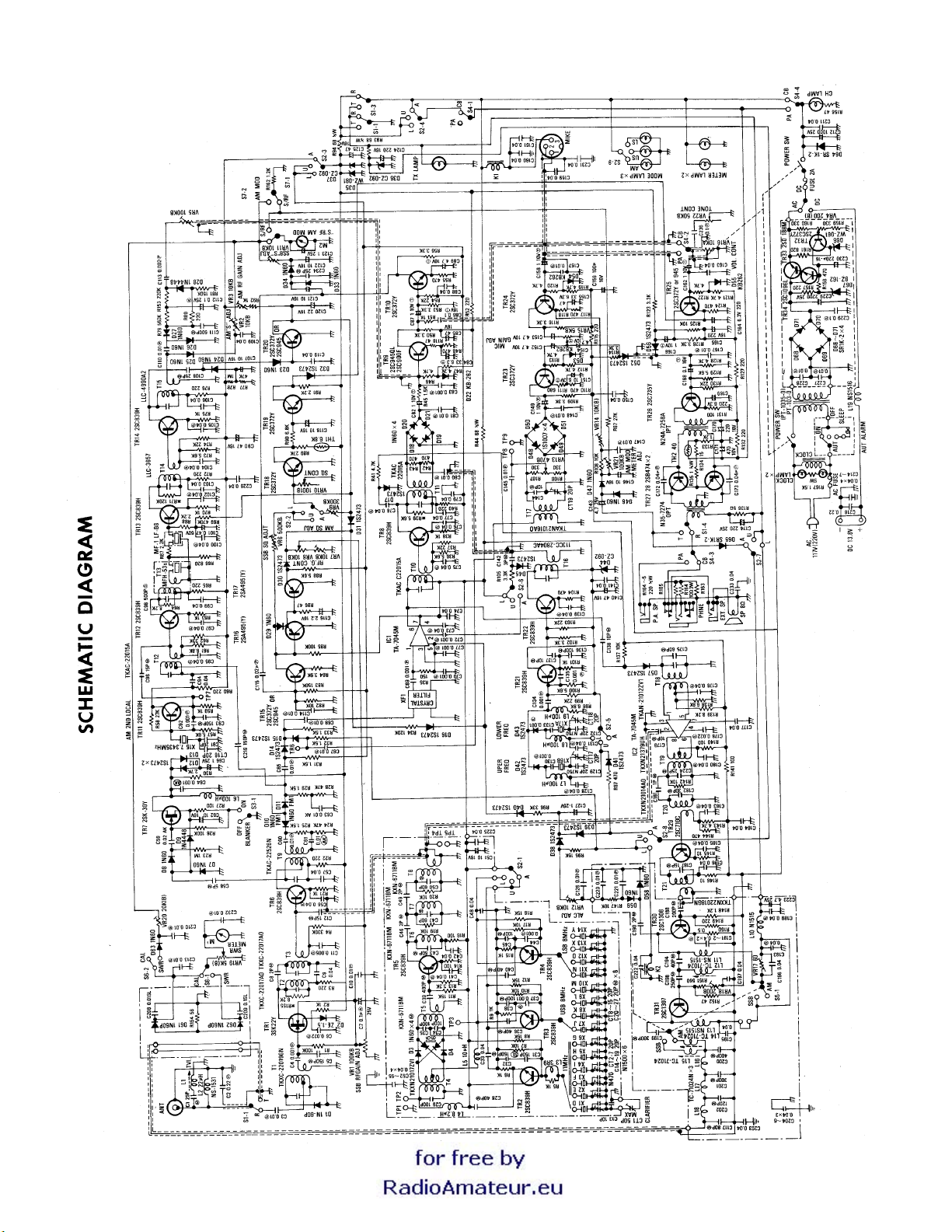
REPLACEMENT PARTS
SEMI CONDUCTORS
SYMBOL DESCRIPTION PART NUMBER
TR- 1 3SK22Y RX RF Amplifier5001-046
TR-2 2SC893H 11 MHz Band Oscillator 5001-014
TR-3 2SC839H 8 MHz Band Oscillator (USB) 5001-014
TR-4 2SC839H 8 MHz Band Oscillator (LSB) 5001-014
TR-5 2SC839H 19 MHz Local Amplifier 5001-014
TR-6 2SC839H RX I 1st Mixer5001-014
TR-7 2SK30Y Noise Amplifier5001-047
TR-8 2SC839H SSB RX 7.8 MHz Amplifier 5001-014
TR-9 2SC90OF RX 1st AF Amplifier
TR-10 2SC372Y SSB RX AGC Amplifier 5001-020
TR-11 1 2SC839H AM 2nd Local Oscillator 5001-014
TR-12 2 2SC839H AM RX 2nd Mixer5001-014
TR-13 3 2SC839H AM 455 kHz IF Amplifier 5001-014
TR-14 4 2SC839H AM 455 kHz IF Amplifier 5001-014
TR-15 2SC372Y SSB AGC Amplifier 5001-020
TR-16 6 2SA495Y SSB AGC Amplifier 5001-048
TR-17 7 2SA495Y SSB AGC Amplifier 5001-048
TR-18 8 2SC372Y Squelch Amplifier5001-020
TR-19 9 2SC372Y Squelch Amplifier5001-020
TR-20 2SC372Y AM AGC Amplifier5001-020
TR-21 2SC839H Carrier Oscillator5001-014
TR-22 2SC839H Buffer Amplifi er5001-014
TR-23 2SC372Y SSB Mike Amplifier 5001-020
TR-24 2SC372Y SSB/AM Mike Amplifier 5001-020
TR-25 2SC372Y RX 2nd AF Ampl i fier 5001-020
TR-26 2SC735Y RX AF Driver Am pl i fier 5001-021
TR-27,28 2SB47A AF Power Amplifier 5001-049
TR-29 2SC710C TX Pre-driver5001-002
TR-30 2SC1306 TX Driver5001-050
TR-31 2SC1307 TX Final 5001-071
TR-32 2SC372Y Voltage Regul ator5001-020
TR-33 2SDI80M Voltage Regulator5001-073
TR-34 2SC1096L Voltage Regulator 5001-064
IC-1 1 TA7045M TX or SSB IF Amplifier 5001-001
IC-2 TA70A5M TX Balance Mixer 5001-001
Page 9

REPLACEMENT PARTS
DIODES
SYMBOL DESCRIPTION PART NUMBER
D- 1, 18,19,20,21,61,62 1 N60P Diode 5001-134
D-2 ZEO1.5 Zenor Diode 5001-147
D-3,4,5,6,7,8,23,24,25, 1 N60 Diode 5001-080
26,27,29,33,34,46,47,
58,59,63
D-9,28 1 N4448 Diode 5001-146
D-1 0,11 1N60-FM1
D-1 2,13,14,15,16,17,31, 1S-2473 Diode 5001-128
38,4O,42,43,45,52,56,
57
D-22,53,54,55 KB-262 Silicon Varistor 5001-122
D-30,32,39,41 1S-2473 Diode 5001-128
D-35 WZ-081 Zenor Diode 5001-130
D-36,37,44 CZ-092 Zenor Diode 5001-152
D-48,49,50,51 1S-1007 Diode 5001-120
D-64,65,68,69,70,71 SR1 K-2 Diode 5001-129
D-66 WZ-061 Zenor Diode 5001-131
D-67 BZ-162 Zenor Di ode 5001-143
TH- 1 TD5-C268 Thermistor 5001-127
TH-2 TD8A-040 Thermistor 5001-151
INDUCTANCES
SYMBOL DESCRIPTION PART NUMBER
L-I T.V.I. Trap 3 1/2 turn 5006-042
L-2 Peaking Coil NS-1531 (LD-010) 5006-139
L-3 LF-3R9, 3.9uH Micro Inductor 5006-140
L-4 LF4-8R2, 8.2uH Micro Inductor 5006-145
L-5 LFA-100, 10uH Micro Inductor 5006-146
L-6,7,8,9 LF-101, 100uH Micro Inductor 5006-141
L-10,1 1,13 TX RF Coil NS-1515 515 (LD-01 1) 5006-142
L- 12,14,15 TX Filter Coil TC-71024 w/core (LC-018) 5006-116
L- 16,17,18 TX Filter Coil TC-71024N w/o core 5006-116
L-19 Power Choke Coil NS-1516 (LE-003) 5006-144
(LC-051)
Page 10

REPLACEMENT PARTS
TRANSFORMERS
SYMBOL DESCRIPTION PART NUMBER
T-1 TKXC-22019GN RX Antenna Coil (LA-028) 5006-125
T-2,3 TKXC-22017AO RX RF Coil (LA-025) 5006-126
T-4 TKXN-21017ZVI 19MHz Local Coil (LA-024) 5006-127
T-5,6,7,8 KXN-6711BM 19MHz Local Coil (LA-004) 5006-128
T-9 TKAC-22526N 7.8MHz IF -Coi l (LA-038) 5006-147
T-10,11,12 TKAC-22015A 7.8MHz IF Coil (LA-027) 5006-131
T-13 MFH-53S Mechani cal Filter 5023-007
T-14 LLC-3657 A M 455kHz IF Coil (LB -003) 5006-078
T-15 LLC-4990A 2 A M 455k Hz IF Coil (LB -005) 5006-079
T-16 11 3CC-2804A C Carri er OSC Coil (LB -0 13) 5006-133
T-17 TK A N-21016A O B .M. Coil (LA-023) 5006-134
T-18 TK A N-21012ZV I TX Coil A (LA-022) 5006-135
T-19 TK XN-21379UH TX Coil B (LA-021) 5006-136
T-20 TK XN-21014AO TX Coil C (LA-020) 5006-137
T-21 TK XN-22018GN TX Coil D (LA-026) 5006-138
I.P.T. N-24A-7258A Input Trans. (TF -027) 5007-021
O.P.T. N-35-7274B Modulation Trans. (TF -028) 5007-022
P.T. PT-1 03-0 Power Trans. (TF -029) 5007-025
CRYSTALS
SYMBOL DESCRIPTION PART NUMBER
X-1 HC-25U 11.000 MHz. 5003-058
X-2 HC-25U 11.050 MHz. 5003-059
X-3 HC-25U 11.100 MHz. 5003-060
X-4 HC-25U 11.150 MHz. 5003-061
X-5 HC-25U 11.200 MHz. 5003-062
X-6 HC-25U 11.250 MHz. 5003-063
X-7 HC-25U 8.1665 MHz. 5003-064
X-8 HC-25U 8.1765 MHz. 5003-065
X-9 HC-25U 8.1865 MHz. 5003-066
X-10 HC-25U 8.2065 MHz. 5003-067
X-1 I HC-25U 8. 1635 MHz. 5003-068
X-12 HC-25U 8.1735 MHz. 5003-069
X-13 HC-25U 8.1835 MHz. 5003-070
X-14 HC-25U 8.2035 MHz. 5003-071
X-15 HC-25U 7.3435 MHz. 5003-072
X-16 HC-25U 7.7985 MHz. 5003-073
X-17 HC-25U 7.8015 MHz. 5003-074
XF-1 7.8 MHz. Crystal Filter KF07F22F 5023-008
VARIABLE RESISTORS
SYMBOL DESCRIPTION PART NUMBER
VR- I 100KB-3KVSF10-5BM Semi-fixed 5008-030
VR-2,3,7,11,12,14 IOKB-2KVSFIO-6BM Semi-fixed 5008-007
VR-4 20OB-3KVSF10-5BM Semi-fixed 5008-041
VR-5,21 I00KB-2KVSFI0-6BM Semi-fixed 5008-031
VR-6 500KB-2KVSF10-6BM Semi-fixed 5008-063
VR-8 Variable for RF Gain (RV-01 7)
VR-9 300KB-2KVSF10-6BM Semi-fixed 5008-066
VR-10 Variable for squelch (RV-0 18)
VR-1 3 470 ohm B Solid Volume SR19R-155 5008-034
VR- 15,19 Variable for SWR, CAL, MIKE,
GAIN Control (RV-0 16)
VR-16 Variable for AF, VR (RV-0 15)
VR-17 WK19R-60 ohm 2W Semi-fixed Wired 5008-035
VR-18 200B-2KVSF10-6BM Semi-fixed 5008-036
VR-20 20KB-2KVSF10-6BM Semi-fixed 5008-008
Page 11

REPLACEMENT PARTS
VR-22 Variable for Tone Control (RV-086)
SWITCHES
SYMBOL DESCRIPTION PART NUMBER
Channel Selector Switch SR-010 or 5009-020
SR-083 (RL-2.4.24)
Model Switch SR-012
Push Switch SW-022 (IFS-4U-7)
S6-1,2 Push Switch SW-009 (IFS-2U-1 1)
RESISTORS
SYMBOL DESCRIPTION PART NUMBER
R-44,93,94 68 ohm
R-164,165 220 ohm 1/2
R-79 560 K ohm
R-69 470 K ohm
R-4 330 K ohm 1/4W Carbon
R-80,153 220 K ohm
R-81,83 150 K ohm
R-1,26,85 100K ohm
R-71,34 120 K ohm 1/4W Carbon
R-24,28,77 47 K ohm
R-62,96 33 K ohm
1/2W
1/4W
1/4W
1/4W
1/4W
1/4W
1/4W
1/4W
Carbon
W
Carbon
Carbon
Carbon
Carbon
Carbon
Carbon
Carbon
Carbon
RESISTORS (Continued)
SYMBOL DESCRIPTION PART NUMBER
R-58,89 27 K ohm
R-37,54,74,99,103, 22 K ohm
130
R-8,11,12,18,95, 15 K ohm
R-7,10,17,19,20,82, 10 K ohm
108,125,142,147
R-64,139 8.2 K ohm 1/4W
R-61,90,98,138 6.8 K ohm
R-36,57,73,88,100, 5.6 K ohm
129,39
R-46,47,112,113, 4.7 K ohm 1/4W
119,120,121,122,
128,143
R-1 3,50,53,56,105, 3.3 K ohm
109,114,116,123,
126
R-84 3.9 K ohm 1/4W
R-30 2.7 K ohm
R-67,68,91 2.2 K ohm
R-25,29,31,32,33, 1.5 K ohm
45
R- 133,148 1.2 K ohm
R-2,5,6,9,15,21,38, I K ohm
51,59,63,70,75,
92,101
R-66 820 ohm 1/4W
R-42,48,55,104,1 10, 470 ohm
117,124,144
R-106,107 330 ohm
R-3,22,40,65,72,76, 220 ohm
115,127,132,149
1/4W
Carbon
1/4W
Carbon
1/4W
314W
Carbon
1/4W
Carbon
1/4W W
1/4W
Carbon
1/4W
Carbon
1/4W
1/4
W Carbon
1/4,
W Carbon
1/4
Carbon
Carbon
1/4W
Carbon
1/4
W Carbon
1/4W
Carbon
Carbon
Carbon
Carbon
Carbon
Carbon
Carbon
R-35 150 ohm
R-14,16,27,131,140, 100 ohm
1/4W
1/4W
Carbon
Carbon
Page 12

REPLACEMENT PARTS
149
R-86,152,118 47 ohm
R-49 22 ohm
R-134 15 ohm
1/4W
1/4 W
1/4W
REPLACEMENT PARTS
R-1 45,146 10 ohm
R-150 0.5 ohm
R-23,78 1 M ohm
RESISTORS (Continued)
SYMBOL DESCRIPTION
R-167 1.5K ohm 5W Cement
R-151 560 ohm 1/4 W Carbon
R-137 10 K ohm 1/ 4 W Carbon
R-155 8.2K ohm 1/4W W Carbon
R-41 4.7K ohm W Carbon
R-102 3.3K ohm W Carbon
R-162 1.2K ohm W Carbon
R-43,97,158 470 ohm W Carbon
R-1 59,160 330 ohm 1/4 W Carbon
R-161 820 ohm
R-52,60,157,169 220 ohm 1/4 W Carbon
R-154 56 ohm 1/4 W Carbon
R-156 47 ohm 1/4 W Carbon
R-87 27 K ohm 1/4 W Carbon
R-111 680 ohm 1/4 W Carbon
1/4
1/4W W
1/4W
1/4W
W Carbon
Carbon
Carbon
Carbon
Carbon
Carbon
Carbon
CAPACITORS
SYMBOL
CT-1 Air Voricon MAX 50pF (CV-009)
CT2-19 Ceram i c Trimer CV-008 or CV-0 17
C-236 0.002uF 50V Disc
C-9,33,42,48,52,53,54,55,57,74,77,79,88,94,99,103,106,109,119,141,150,159,222,160,161,163,177,231,233,184,186,226,195,196,197,203,
204,205,225,211, 214,215,216,217, 128,131 -0.04uf 50V Disc
C-84,155 6.3V/33 uf Total
C- 151 6-3V/ 1 0 uf Total
C-89,152,153,154 10v/4.7uf Total
C-82,87,149,158, 10v/1 uf Total
162,166
CAPACITORS (Continued)
SYMBOL DESCRIPTION PART NUMBER
C-7,86,112,168 25V 0.1 uf Aluminum 5018-046
C-120 16V/22 uf Electrolytic 5018-042
C-207 25V/2200uf Electrolytic 5018-016
C-171 16V/470
uf
Electrolytic 5018-024
C-1 24,165,170,230 16V/220 uf Electrolytic 5018-023
C-164,169 6.3V/220 uf Electrolytic 5018-044
C-156 16V/100uf Electrolytic 5018-012
C-85,90,125,140 16V/47uf Electrolytic 5018-034
C-51,62,107,118, 16V/10uf Electrolytic 5018-005
121,122,146
C-1 43,223 25V/4.7uf Electrolytic 5018-036
C-1 16 16V/2.2uf Electrolytic 5018-048
C-66,127,123 25V/1uf Electrolytic 5018-037
Page 13

C-101 50V/0.47 uf Electrolytic 5018-038
C-174 25V/220 uf Electrolytic 5018-033
C-212 25V/1000uf Electrolytic 5018-039
C-1 11 500pF 50V Silvered Mica
C-39,200 400pF 50V Silvered Mica
C-199,201 300pF 50V Silvered Mica
C-198 250pF 50V Silvered Mica
C-188 200pF 50V Silvered Mica
C-5,32,93,219 150pF 50V Silvered Mica
C-202 120pF 50V Silvered Mica
C-29,34,35,38,45, 100pF 50V Silvered Mica
136
C-1 17 8OpF 50V Silvered Mica
C-43,47,50,175 60pF 50V Silvered Mica
C-28,36,40,194 40pF 50V Silvered Mica
C-182 30pF 50V Silvered Mica
C-1,224,234 25pF 50V Silvered Mica
C-20,21,22,23,24, 20pF 50V Silvered Mica
25,26,27,108
C-1 2,96,187 15pF 50V Silvered Mica
C-1 37,138,144,179 10pF 50V Silvered Mica
C-58 5pF 50V Silvered Mica
C-142 8pF 50V Silvered Mica
C-8,46,49,190 2pF 50V Silvered Mica
I 81 1pF 50V Silvered Mica
C-31 150pF 50V Disc
C-208,209 0.01uF 50V Disc
C-98 500pF 50V Styrol 5017-005
SYMBOL DESCRIPTION PART NUMBER
C-59 0.02uf 50V Dis c
C-61,63,3 0.01 uF 50V Disc
C-64 0.001 uF 50V Disc
C-236 0.1 uF 50V Mylar
C-2,213 0.22uf 50V Mylar 5017-001
C-41,56,73,75,76, 0.04uF 50V Mylar 5017-003
78,95,97,100,
102,104,105,139,
176,180,183,185,
191,192,193,206,
189,172,173
C-6,178 0.022uF 50V Mylar
C-1 15 0.02uF 50V Mylar 5017-002
C-60,65,67,68,80, 0.01 Uf 50V Mylar
81,110,114,126,
227,228,229,232,
145,221,213,147,
148,157,167,210,
220
C-1 1 0.005uF 50V Mylar
C-1 13 0.0021LF 50V Mylar
C-4,10,37,44,69, 0.001 uF 50V Mylar
70,71,72,83,92
130,133,134,135
C-14,15,16,17,18,19 20 pF 50V Disc N- 1500
C-91,129,132 20 pF 50V Disc N-750
C-13 10pF 50V Disc N-470
C-136 5 ohm 5W Cement
C-163 10 ohm 3W Metalized 5019-003
C-135 1 ohm
1/2W
Metalized 5019-006
Page 14

REPLACEMENT PARTS
MISCELLANEOUS PARTS
PARTS NUMBER
Antenna Connector 5010-009
Ext. SP/ PA Jack (AJ319) 9) 5010-015
Crystal Socket S -DO105 5010-002
Speaker EAS-lOP03S(SP-003) 5012-009
Relay Socket 5010-010
DC Power Plug PC-211 5010-034
DC Power Jack SC234 5010-035
Microphone Plug SM- 143 5010-022
Microphone Jack SM-143 5010-018
Relay AE-31 44 (RL-003) 5024-004
Sub-minature Relay MT-2 VN 5024-005
Meter type A-49 SWR 5014-011
Meter type (MF-033) 5014-010
Fuse Holder NRF00301-2 5028-004
Digital 'Clock DT-H 5009-024
Headphone Jack 8P(LJ-035) 5010-037
AC Power Cord W/plug(SVT -1) 5015-011
Pilot Lamps 14V/3OmA 5013-017
Front Panel (die-cast) 5020-024
Metal Cabinet (top) 5020-025
Metal Cabinet (bottom) 5020-026
Panel for Clock 5020-027
Brand Plate 5027-030
Front Plate 5027-031
Volume Knob 5022-029
Clarifier Knob 5022-030
Clock Knob (A) 5022-031
Clock Knob (B) 5022-032
Channel Knob Complete 5022-025
Push Switch Knob 5022-033
FCC Plate 5027-016
Microphone Plate 5027-012
Pedestal (20m/m x 20m / m) 5021-027
Pedestal (20m/m x 16m / m) 5021-028
Styrofoam Box 5030-023
Display Box 5030-024
Instruction Booklet 5031-011
Styrofoam Box for Stand Mike 5030-025
FCC Application Form
Warranty Card
Base Station Microphone (P-3001A)
Page 15

Page 16
Page 17
Page 18
 Loading...