

Page 1

Page 2

Page 3

1
Version 1.1
Dear Customer!
Thank you for choosing our product.
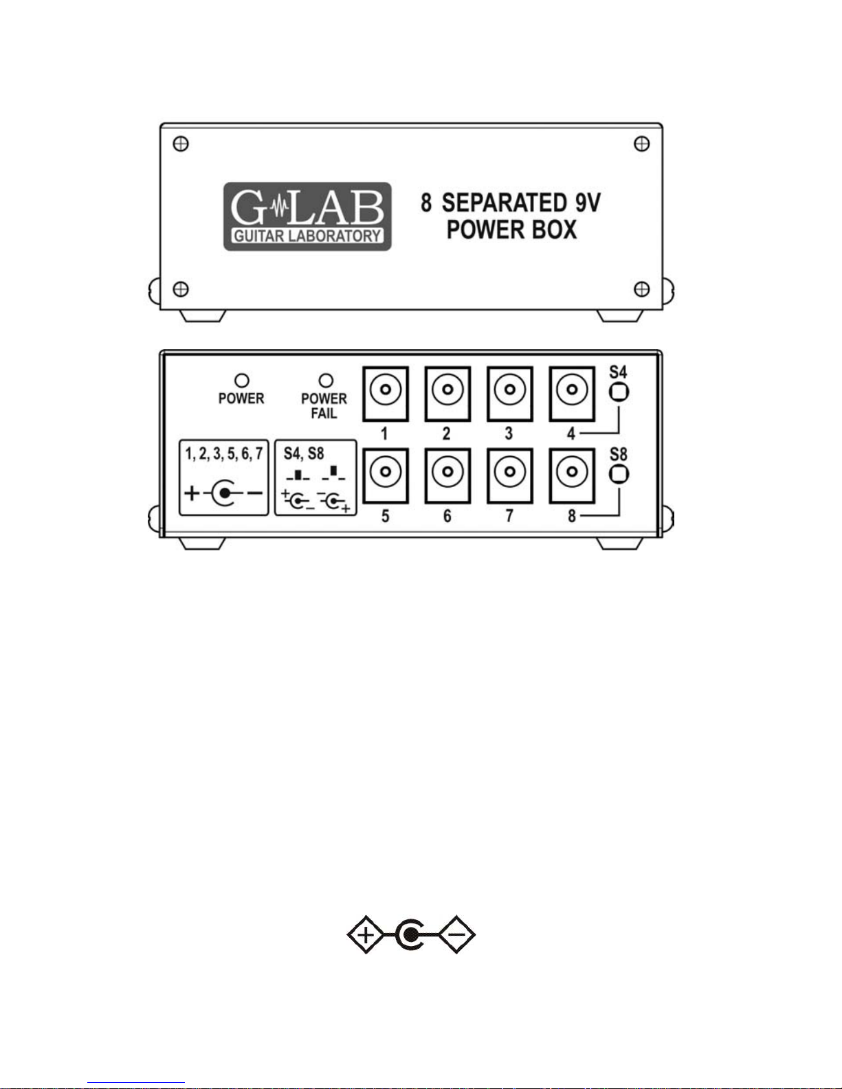
8 SEPARETED 9V POWER BOX (PB-1) is eight outputs adapter to
supply guitar effects with 9V direct current (DC). Each of eight outputs is full
galvanic separated (isolated from input and others outputs). Separation
enables to avoid the ground loops and to obtain 12V and 15V DC voltages by
using offered by G LAB adapters and 18V DC voltage by using simple to do
cable. Maximal current of each output is 0,35A under the condition of not
passing 1A for each section (outputs 1 to 4 and 5 to 8, see the scheme).
Each of PB-1 outputs posses short circuit and thermal protection. Outputs
No. 4 and 8 posses switches to change voltage polarity.
Thanks to applied in the PB-1 SMPS technology:
- DC output voltage is guaranteed in the range from 100V to 240V line
voltage
- there is high output power in proportion to small size and weight
- PB-1 doesn’t possesses typical mains transformer which generates
electromagnetic field interferences receive d by other devices situated
near to it (e.g. inductors in the wah-wah effect).
Package content
PB-1 Power Box 1 pc
Mains cable 1 pc
9V 40 cm cable 2 pcs
9V 80 cm cable 4 pcs
9V 120 cm cable 2 pcs
M3 screws 4 pcs
Velcro fastener 4 pairs
Heat shrink tube 10 pcs
Cable label 30 pcs
Page 4
2
Structure
Mains connecting
PB-1 should be supplied from power outlet equipped with protective
contact (so called „protective earth”). It can be supplied from 100V nominal line
voltage (Japan), 120V (USA, Canada) and 230V (Europe, Australia). Adapter
features power socket according to the IEC320 C14 standard to which is
connected the mains cable with a connector appropriate for a given country.
Connecting to the effects
Before connecting the PB-1 to the effect it is needed to:
- check if the effect should be supplied with DC voltage.
If so check if it is 9V
- check if the effect features input power supply polarization
CTR – (centre negative)
- check required supply current (if effect can be supplied from
9V battery the supply current check isn’t required)
Page 5

3
If it the opposite connector polarity is required (CTR +) it is needed to use the
output No. 4 (or 8) with changed polarity (diagrams on the box show location
of the S4 (or S8) switch and polarity).
ATTENTION: Damages caused by improper power supply causes the loss of
the warranty. Do not connect the adapter to the effects which
need to be supplied from alternating current (AC).
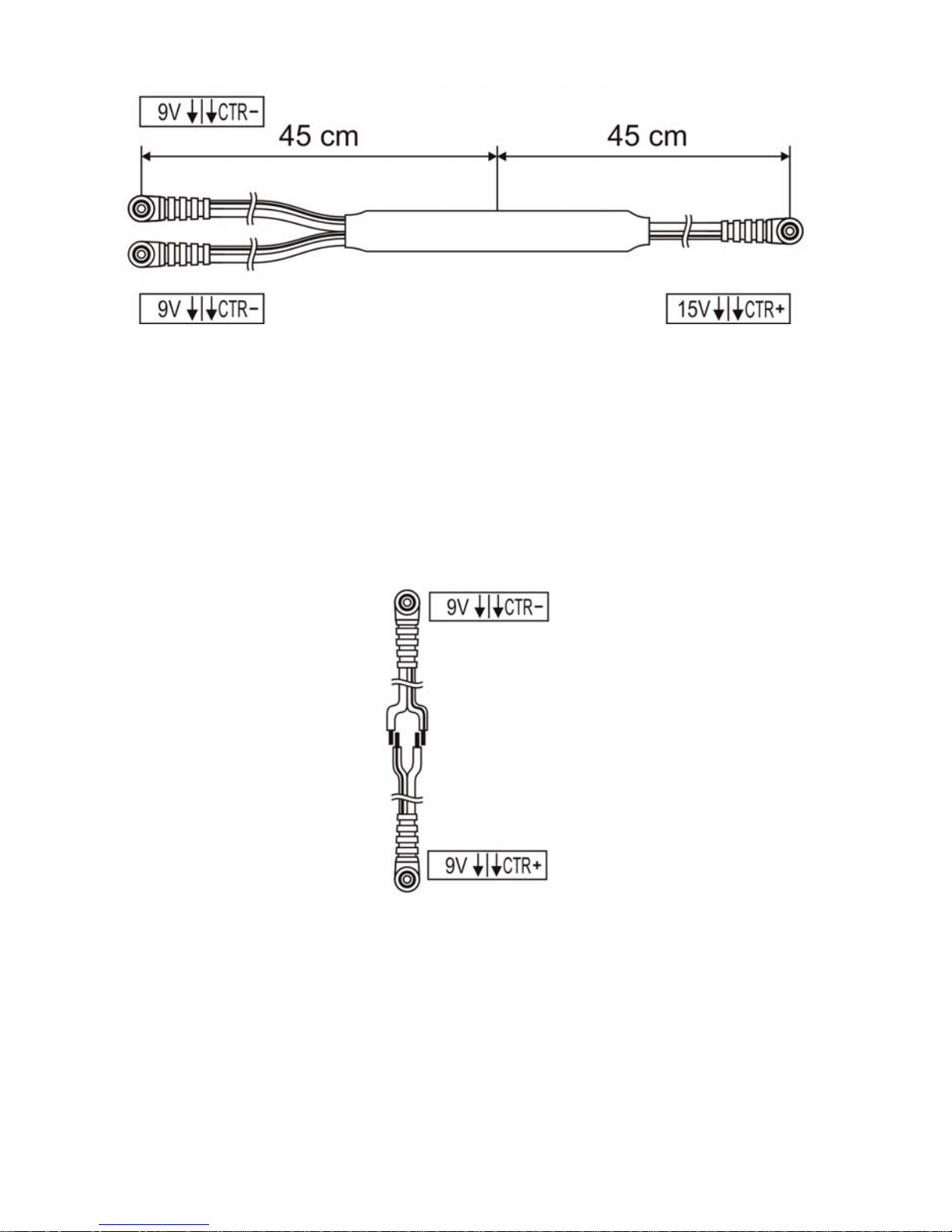
It is recommended to cover the connectors of changed polarity cable with
attached labels. The diagrams below explain descriptions on those labels.
For the effects that require 12V DC voltage it is needed to use individually
bought Adapter 2x9V/12V DC (CTR neg. 0,35A) - product code 00865.
For the effects that require 15V DC voltage it is needed to use individually
bought Adapter 2x9V/15V DC (CTR pos. 0,35A) - product code 00866
Page 6
4
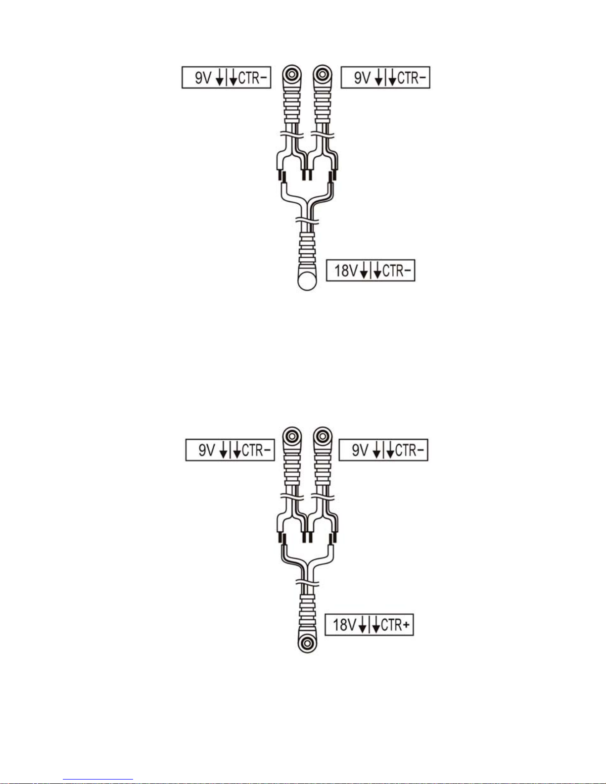
Persons with qualifications and experiences in electrotechnics can
prepare the cables shown below by themselves.
The packet contains heat shrink tubes and labels for cables with descriptions.
The diagram below shows the cable for the 9V effects with polarity CTR +
(centre positive) (9V CTR - input, 9V CTR + output).
The diagram below shows the cable for the 18V effects with polarity CTR (centre negative) (two 9V CTR - inputs, one 18V CTR - output).
Page 7
5
The diagram below shows the cable for supplying the effects requiring 18V
DC with polarity CTR + (centre positive) (two 9V CTR - inputs, 18V CTR +
output).
Page 8
6
Using separated supply is the basic agent enabling to build the guitar
systems without ground loops and supply crosstalk (the influence of variable
load of one effect on the second). The best solution is to use separated
supply of every effect. The exception from this is possible when the following
conditions are met:
- effects are placed in pedalboard or in other place fare from big mains
transformers
- the effects are in the same part of the path (e.g. on the effects or
before the amp input) and are placed one by one in the signal path
- the effects aren’t the overdrive, boost type effects (with high gain) or
the effects consume the current impulsively e.g. those equipped with
LED display.
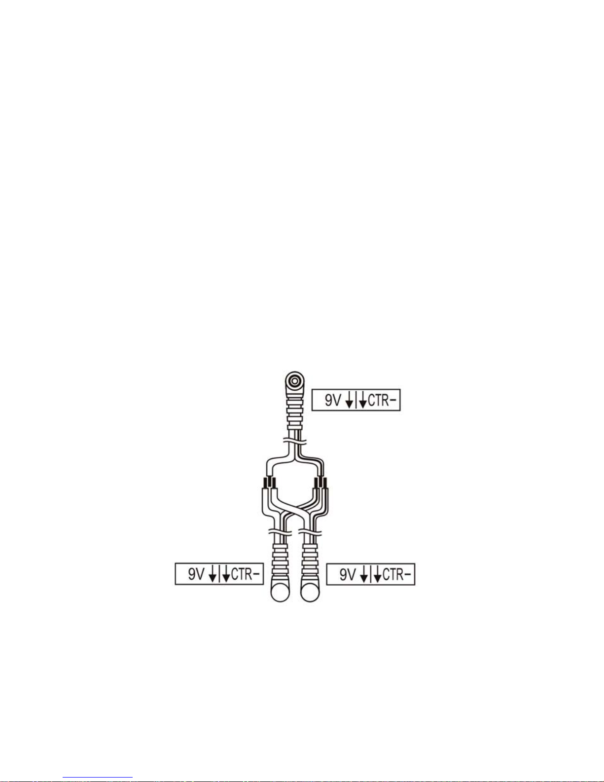
The diagram below shows the cable for supplying two 9V effects with polarity
CTR - (centre negative) from one 9V source (9V CTR - input, two 9V CTR outputs).
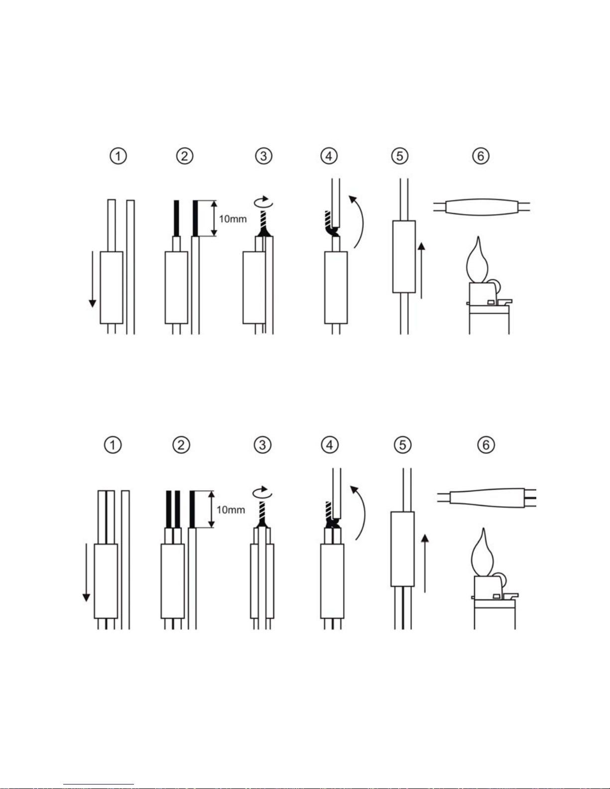
To link the cables you need basic tools and heat shrink tubes (provided with
adapter). Strong screwing together the wires and using the heat shrink boot
assure reliability and durability of the linking even for three wires.
Page 9
7
Linking wires without soldering
The diagram below shows the way of linking two wires.
The diagram below shows the way of linking three cables.
Page 10
8
Mounting
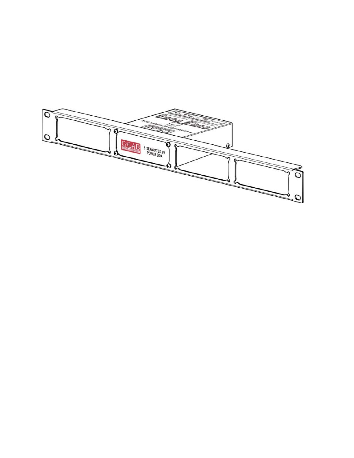
In case of mounting in pedalboard it is possible to use the Velcro
fasteners provided with the adapter or to use M4 screw (adapter base posses
bushings with M4 threads). The adapter can be also fastened to the rack 19’
systems by the use of 1U RMS Panel (product code 00829) and M3 screws
supplied with the adapter.
Technical parameters
Dimensions: width 108 mm
Depth 130 mm
Height 40 mm
Weight 0,9 kg
Power supply nominal 100V - 230V
Page 11

9
Page 12

10
Page 13

11
EMC/EMI & Certificate of conformity
EMC/EMI
This device has been designed and manufactured to conform with directives
and standards in the field of safety operations and electromagnetic
interference.
This device uses and can radiate radio frequency energy and, if not installed
and used in accordance with the instructions, may cause harmful interference
to radio communications. However in spite of performing below standards
there is no guarantee that interference will not occur in a particular
installation. If this device does cause harmful interference to radio or
television reception which can be determined by turning the device on and
off, the user is encouraged to try to correct the interference by one or more of
the following operations:
● Reorient or relocate the receiving antenna.
● Increase the separation between the device and receiver.
● Connect the device into an outlet on a circuit different from that to
which the receiver is connected.
● Contact with the manufacturer.
● Consult the dealer for help.
Certificate of Conformity
ELZAB S.A., ul. Kruczkowskiego 39, 41-813 Zabrze, Poland,
hereby declares on own responsibility that the following product:
8 SEPARETED 9V POWER BOX (G LAB PB-1)
that is covered by this certificate and marked with CE 07 label conforms
with following standards:
PN-EN 60065:2004
Safety requirements for mains operated electronic and
related apparatus for household and similar general use
PN-EN 551031:1998
Product family standard for audio, video, audiovisual and
entertainment lighting control apparatus for professional
use. Part 1: Emission.
PN-EN 551032:1998
Product family standard for audio, video, audiovisual and
entertainment lighting control apparatus for professional
use. Part 2: Immunity.
with reference to regulations in following directives:
73/23/EEC, 2004/108/EEC
Issued in Zabrze, March 2009
Jerzy Biernat
President of the ELZAB S.A. Board of Directors
Page 14

12
DO NOT PLACE THIS PRODUCT INTO THE WASTE CONTAINER !
This device is marked with a cross-lined waste container symbol
according to 2002/96/EU Directive on Waste Electric and Electronic
Equipment.
Such marking informs that after usage equipment can not be
trashed together with other household waste.
An user obligation is to return wasted equipment to a party collecting wasted
electric and electronic equipment. Parties collecting such equipment organise a
system, including local collection points, shops and other units, allowing to return
such equipment. This Directive assures an user free of charge utilisation of such
delivered equipment.
This device is made of materials which can be recycled or utilised after b ecoming
out of use. Proper handling of wasted electric and electronic equipment reduce
demand for row materials and contribute in avoiding harmful consequences for
environment and health of people caused by dangerous components and not
proper storing and utilising of such equipment.
User Manual, Drawing No. G60INA00
Page 15

Page 16

 Loading...