

GKL GKIT BABY PRE v4.2 Assembly Manual
Assembly Guide
“Baby Pre”v4.2
Designed by:
Robert-Eric & Peter Gaskell
March 2017
Assembly Guide
Thank you for your interest in the GKit Baby Pre. The Baby Pre kit is not only a way
to get an excellent 2-channel mic pre at a very reasonable price, it is also an
educational resource that can help you learn about fundamental analog circuits. One
can choose to simply build the kit and start using the mic pres right away or the kit
can be used to study useful electronics concepts that will help in understanding this
and other audio circuits. The sound character of each channel can be enhanced with
DIYRE 's colour modules or with the build-in transistor amp colour section. When the
front panel colour button is not pressed, the BabyPre is a very clean, open mic pre.
The built in transistor amp colour adds a bit of character when the “colour” button is
pressed. Additional colours are available at:
www.diyrecordingequipment.com/colour
This guide contains all the information you need to build, test, and troubleshoot your
Baby Pre. Significantly more detail is provided in the complete manual. If you are new
to electronics, we recommend that you read chapter one of the complete manual
before starting your assembly. You can find this manual and additional information
about the project on the GKL website at:
www.gklaudio.com/gkit-babypre
Visit our site for:
• Complete Manual
• Schematics
• Laboratory Exercises
• Educational Information
• BOM (Bill of Materials)
• Videos
• Optional Parts and
Add-on Kits
Tools
Required Tools
To assemble the GKit Baby Pre, you will require:
• Soldering Iron
• Fine Electronic Snips
• Solder
• #1 Phillips Screwdriver
We recommend that you also have:
• Solder Sucker
• Multi-meter
• Needle-nose pliers
Before You Start
It is important to note that all of the test points (TPs) must be populated in order for
the Baby Pre to work. The component leads leftover after trimming the diodes,
resistors and capacitors should be used as jumpers on test points. Leave a 1cm loop
of wire above the board so that test points can be easily clipped to for performing
tests and measurements (See Figure 7). Be sure to NOT populate test points 6
and 7 (TP6 & TP7) until after testing the power supply section. This is described
in the "Testing" section of this guide.
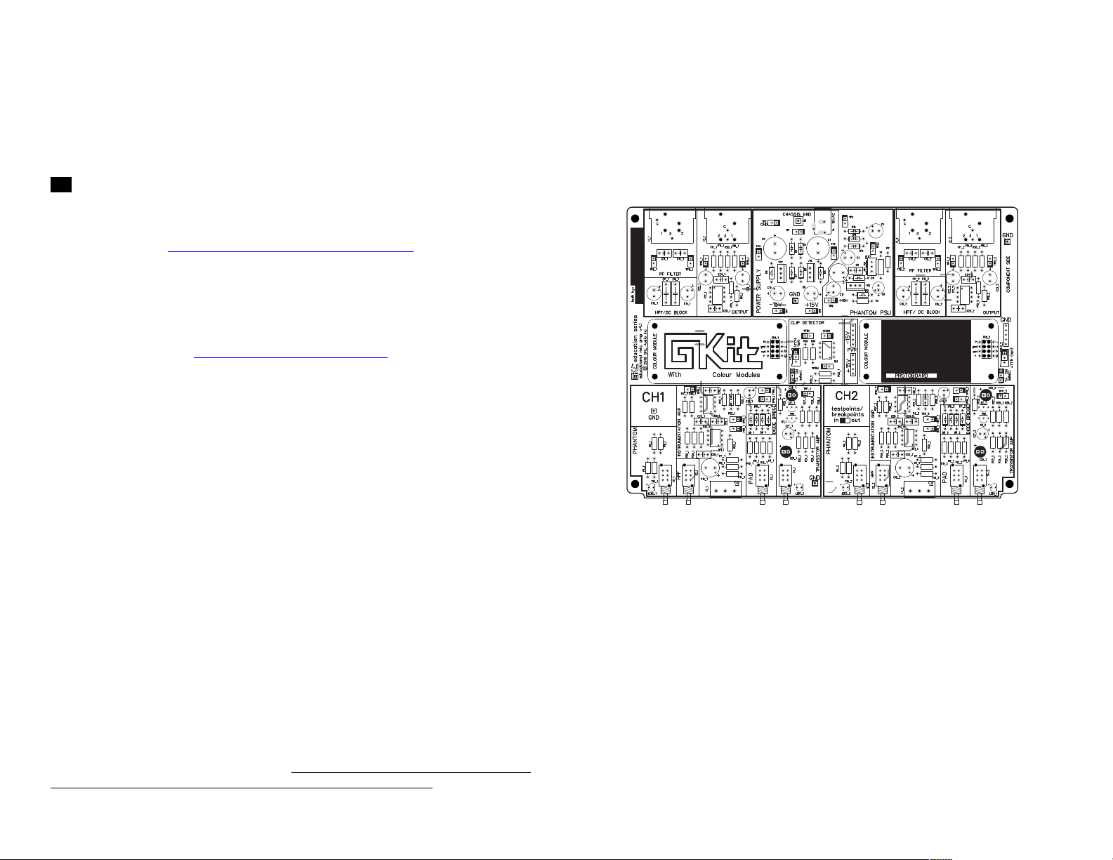
The Board
Your Baby Pre’s circuit board has been carefully laid out to make assembly and
trouble shooting as easy as possible. There is no required harness wiring; all the
components solder directly to the board. All of the parts have been labelled outside
the component footprint so part numbers can be identified after the component has
been populated. The board has both a top and bottom silk screen so signals can be
easily traced through the circuit.
!!!!!!! !
Figure'1.!GKit!Baby!Pre!PCB!Board
• Every board is labelled with its version number. This guide is for board version v4.2.
If you have a different board revision, check at gklaudio.com for information specific to
your run of boards.
• The Baby Pre has two identical channels so many of the components appear twice
on the board (e.g. R4_1 and R4_2). Components in the PSU and Phantom Supply
are not duplicated.
• Not all components get populated, these components are labelled “opt” for “optional”.
The purpose of these optional components is described in the Complete Manual.
• You can write you name on the board's top/left corner.
!
!
!
!
!
!
Components & Options
The components for the GKit Baby Pre have been carefully bagged and labelled to
make assembly as simple as possible. We recommend you populate the components
in order of the bag #s. Start with the resistors and move on to the taller components.
!
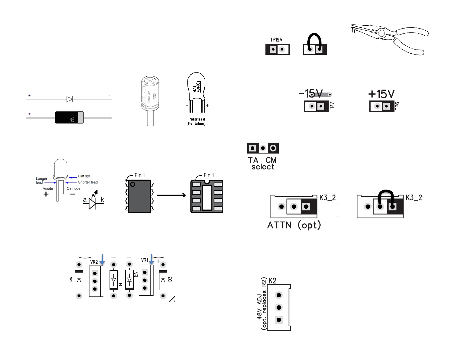
Figure'2.!Diode!1!Polarity!to!follow.
- +
Figure'3.!Capacitor!1!Polarity!to!follow.
!
!
!
Figure'4.!LED!1!Polarity!to!follow.!
!
!
Figure'5.!IC!chip!direction!to!follow.
Regulator heat-sink
Figure'6.!Voltage!Regulator!orientation.!
Metal!plate!(heat!sink)!is!at!the!back!where!the!small!rectangle!is!located
!!!!!!!!!!! !
Figure' 7.! To! make! test!points!(TPs),! either! bent! a! leftover!resistor!lead!by! hand! or! by!
using!needle!nose!pliers!to!make!a!clean!bend.! !Leave!a!loop!of!wire!above!the!board!for!
clipping!to.!!All!TPs!must!be!populated!for!the!circuit!to!function.
!
!
Figure'8.!Do!not!populate!TP6!or!TP7!until!the!power!supply!has!been!tested.
!
!
'Figure'9.!The!TA/CM!selector!uses!a!31pin!header!and!a! 21 pin!jumper;!
the! center! pin! being ! common! for! the! tw o ! options.! It! is! used! to! select!
between!th e! built1in! transistor!amp! (T A ) ! or!the!plug1in!colou r! module!
(CM)! when! the! “Colour"! butto n! on! the! front! panel! is! pressed.! If! no!
colour!module!is!installed,!the!jumper!should!be!placed!on!TA.!
!
!
!
!!!!!!!!!! !
Figure'10.!K3!is!an!optional!trim!pot!that!allows!the!user!to!control!the!amount!of!colour!
that!is!added.!!K3!is!NOT!provided!with!the!kit.!!If!not!using!K3,!the!test!point!inside!the!
K3!footprint! MUST!be!populated.!!See#the#full#manual#for#more#information#about#setting#
levels#for#the#colour#modules.#
!
!
!
!
Figure'11.!K2!is!an!optional!trim!pot!that!can!be!installed!in!
replacement!of!R2.!!K2!is!NOT!provided!with!the!kit.!If!R2!is!
installed,!this!space!has!to!remain!empty.
!
!
!
!
!
Not'using'K3'
 Loading...