

Page 1
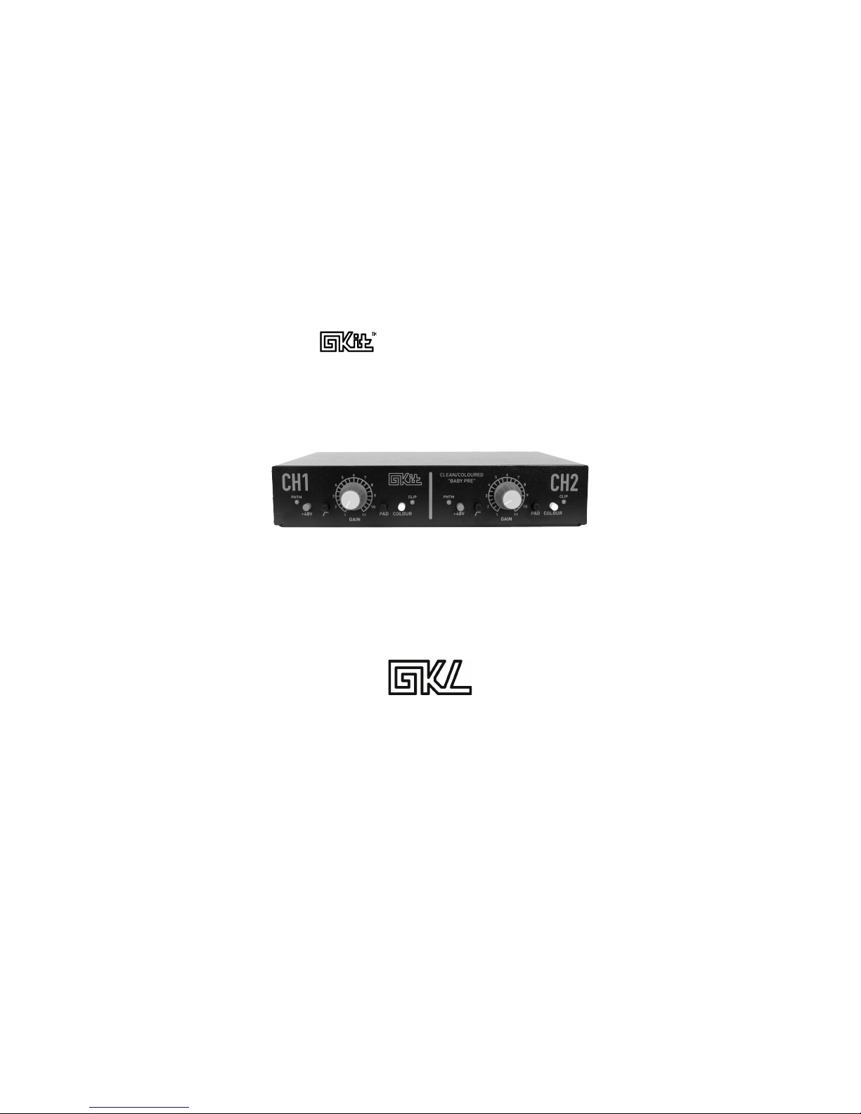
Assembly Guide
“Baby Pre”v4.1
Designed by:
Robert-Eric & Peter Gaskell
December 2016
Page 2
Assembly Guide
Thank you for your interest in the GKit BabyPre. The BabyPre kit is not only a way to
get an excellent 2-channel mic pre at a very reasonable price, it is also an educational
resource that can help you learn about fundamental analog circuits. One can choose
to simply build the kit and start using the mic pres right away or the kit can be used to
study useful electronics concepts that will help in understanding this and other audio
circuits.
contains all the information you need to build, test, and troubleshoot your BabyPre.
Significantly more detail is provided in the complete manual. If you are new to
electronics, we recommend that you read chapter one of the complete manual before
starting your assembly. You can find this manual and additional information about the
project on the GKL website at:
www.gklaudio.com/gkit-babypre
Visit our site for:
• Complete Manual
• Schematics
• Laboratory Exercises
• Educational Information
• BOM (Bill of Materials)
• Videos
• Optional Parts and
Add-on Kits
Tools
Required Tools
To assemble the GKit BabyPre, you will require:
• Soldering Iron
• Fine Electronic Snips
• Solder
• #1 Phillips Screwdriver
We recommend that you also have:
• Solder Sucker
• Multi-meter
• Needle-nose pliers
Before You Start
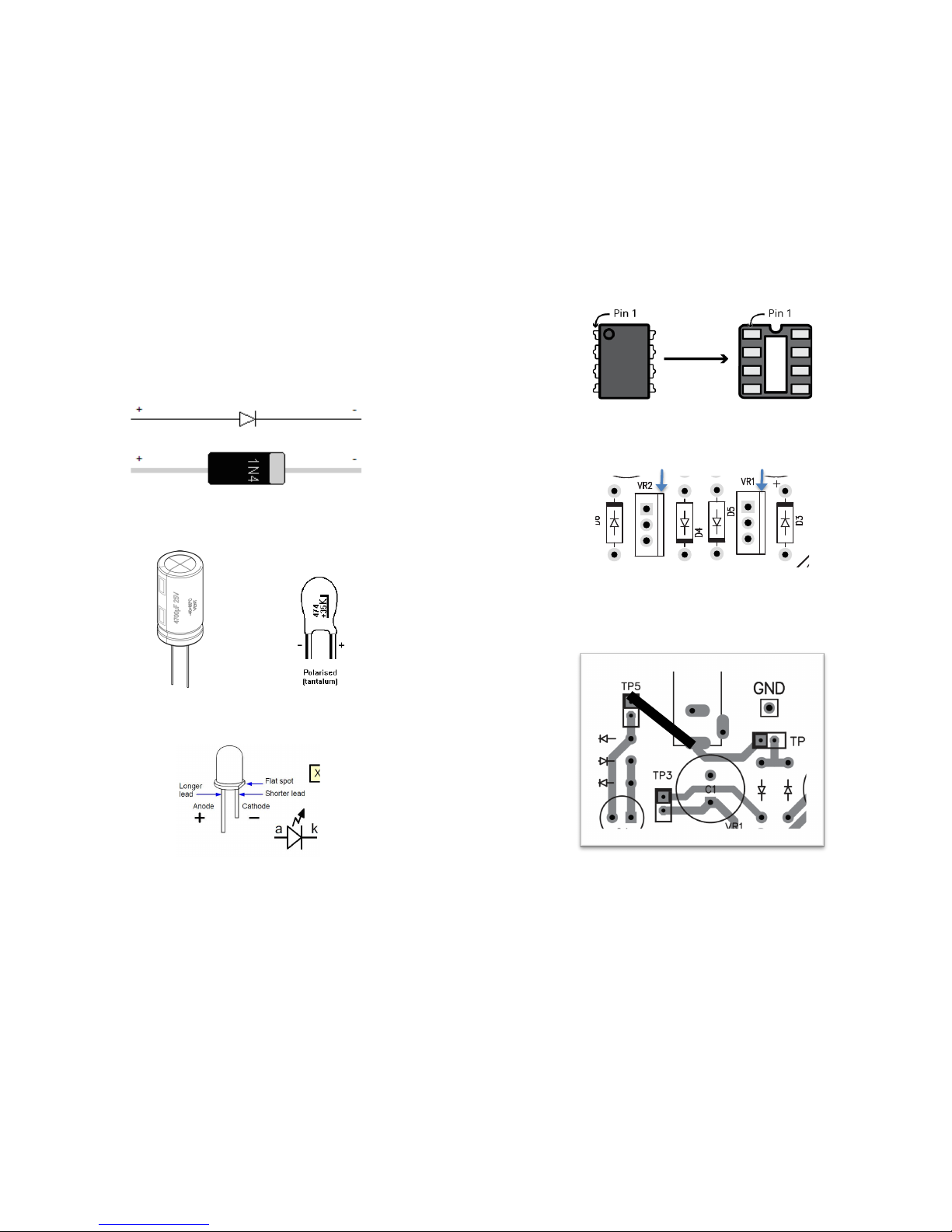
There are a couple important details to note before you start. First, you MUST solder
the additional wire shown in Figure 7 between the power input and test point 5 (TP5)
or your circuit will not work. Second, be sure to NOT populate test points 6 and 7
(TP6 & TP7) until after testing the power supply. This is describe in the "Testing"
section of this guide.
!
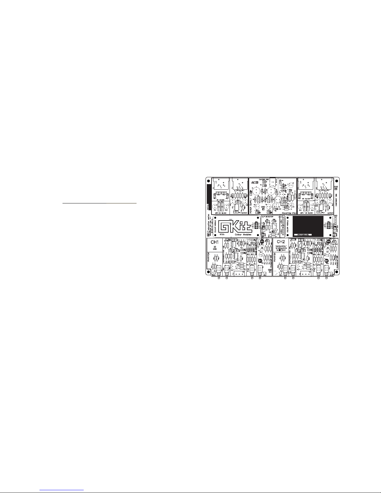
The Board
Your BabyPre’s circuit board has been carefully laid out to make assembly and
trouble shooting as easy as possible. There is no required harness wiring; all the
components solder directly to the board. All of the parts have been labelled outside
the component footprint so part numbers can be identified after the component has
been populated. The board has both a top and bottom silk screen so signals can be
easily traced through the circuit.
!
!"#$%&'()'*+",'-./0'1%&'12-'-3.%4
• Every board is labelled with its version number. This guide is for board version v4.1.
If you have a different board revision, check at gklaudio.com for information specific to
your run of boards.
• The BabyPre has two identical channels so many of the components appear twice
on the board (e.g. R4_1 and R4_2). Components in the PSU and Phantom Supply
are not duplicated.
• Not all components get populated, these components are labelled “opt” for “optional”.
The purpose of these optional components is described in the Complete Manual.
• You can write you name on the board's top/left corner.
!
!
!
!
Page 3
Components
The components for the GKit BabyPre have been carefully bagged and labelled to
make assembly as simple as possible. We recommend you populate the components
in order of the bag #s. Start with the resistors and move on to the taller components.
!
!"#$%&'5)'6"34&'7'138.%",0',3'93883:)
- +
!"#$%&';)'2.<.=",3%'7'138.%",0',3'93883:)
!
!"#$%&'>)'?@6'7'138.%",0',3'93883:)
!
!
!"#$%&'A)'B2'=C"<'4"%&=,"3D',3'93883:)
Regulator heat-sink
!"#$%&'E)'F38,.#&'G&#$8.,3%'3%"&D,.,"3D)''H&,.8'<8.,&'IC&.,'J"DKL'"J'.,',C&'/.=K'
:C&%&',C&'JM.88'%&=,.D#8&'"J'83=.,&4
!"#$%&'N)'Be certain to add the extra wire between the positive (+) transformer
input jack (J1) and TP5. The wire should connect where the solid black line is
shown in the picture above.
!
Page 4

Testing
GKL recommends that you do your final testing of your BabyPre circuit before
mounting the PCB into the enclosure. This will allow easy access to the circuit in
case anything needs to be fixed.
Test the Power Supply First!! Once your PCB is fully populate (Be sure all of the
TPs have been soldered EXCEPT TP6 and TP7) plug the board into the power
transformer. Measure the Volatges at TP6, TP7, and TP8. You should have
approximately +15V DC, -15V DC, and +48V DC respectively. If you have the correct
voltages, install TP6 & TP7 and test the voltages again. If you suddenly DO NOT
have the correct voltages once TP6 & TP7 are installed, unplug the board
immediately and begin troubleshooting.
If the power supply voltages are correct, begin testing the audio circuitry. Even if you
do not have an oscilloscope and function generator or an Audio Test System, you can
confirm the proper performance of your BabyPre using a standard DAW and audio
interface. A Digital Multi Meter (DMM) is useful but not absolutely necessary.
Most common audio interfaces use a standard reference of -14dB FS = +4dBu.
+4dBu is line level for professional audio. You can confirm this by generating a 1kHz,
-14dB FS RMS sine tone in your DAW and measuring the RMS voltage between pins
2 and 3 (or between tip and sleeve of a TRS cable) of your audio interface with a
DMM. The RMS voltage should be 1.228 Vrms.
To test your BabyPre, send a -50dBu (-68 dB FS RMS) 1kHz sine wave out of your
DAW into the BabyPre’s mic input. Return the BabyPre’s output to your DAW and
adjust the gain of the BabyPre such that the signal returns at -8 dB FS (this will be
60dB of gain).
1) Record a few seconds of the output of the BabyPre. Inspect the waveform.
It should be a clean sine wave with no clipping or distortions.
2) Engage the Transistor Amp or Colour Module section. There should be no
significant change in the signal level returning to the DAW. Disengage the
Transistor Amp / Colour Module.
3) Leaving the BabyPre set to 60dB of gain, turn off the signal generator. This
will leave only the BabyPre’s Equivalent Input Noise(EIN) floor. The level of
the signal returning to the DAW should be less than -58 dB FS. This
equates to a noise level of -40dBu and, since there is 60dB of gain applied,
an EIN level less than 100dBu.
4) Change the frequency of your DAW’s signal generator to 20 kHz, you should
see no change in signal level. Change the frequency to 20 Hz, you should
see a 1dB drop in the signal level returning to your DAW.
5) With the signal generator still outputting 20 Hz, engage the HPF button.
There should be approximately a –18 dB drop in signal level at the input to
your DAW.
6) Return the signal generator to 1kHz. Engage the Pad button. There should
be a -19 dB drop in signal level at your DAW’s input.
If all of these tests produce the desired results on both channels of your BabyPre, you
can be confident that it is in good working order. If not, refer to the troubleshooting
section of this Assembly Guide.
Troubleshooting
The majority of problems we see with the BabyPre project are either components that
have been soldered in the wrong orientation or poor solder joints. Visually inspect the
orientation of all polar capacitors (Electrolytic and tantalum capacitors), diodes, LEDs,
voltage regulators, and Integrated Circuits (ICs). Visually inspect the bottom of the
circuit board for solder bridges or suspicious looking solder joints. Try reheating or
adding more solder to any questionable solder joints.
If you cannot identify the source of your problem, you can refer to the troubleshooting
section of the Complete Manual, available at www.gklaudio.com/gkit-babypre. The
Complete Manual contains significantly more detail on best practices while
troubleshooting. If problems persist, see the Policies section of this Assembly Guide
for information on how to contact us for help.
Enclosure and Final Assembly
Once your board is fully assembled and tested, it is time to mount the PCB into the
enclosure. Place the switch caps on the push-button switches and remove the
hardware from the potentiometers. Slide the PCB into the slots on the bottom part of
the enclosure. Put the washer and nut from the potentiometer back on but DO NOT
tighten them yet. Slide the top enclosure on and make sure the XLRs are aligned at
the back. Use the four silver 4-40 screws to attach the top and bottom enclosure
pieces together at the sides of the unit. Use the black self-tapping screws to attach
the XLRs to the rear panel (sometimes a little force is needed to pry the XLRs into
place. The XLRs should extend out from the back of the unit about 1mm. Once the
XLRs are tightened down, tighten the nuts on the potentiometers at the front of the
unit. Finally, turn the potentiometers fully counter clockwise and push the knobs on
making sure the pointers on the knobs are in the correct position.
CONGRATULATIONS! You're GKit should now be complete and ready to use.
!
!
!
!
!
!
!
!
!
Page 5
!
!
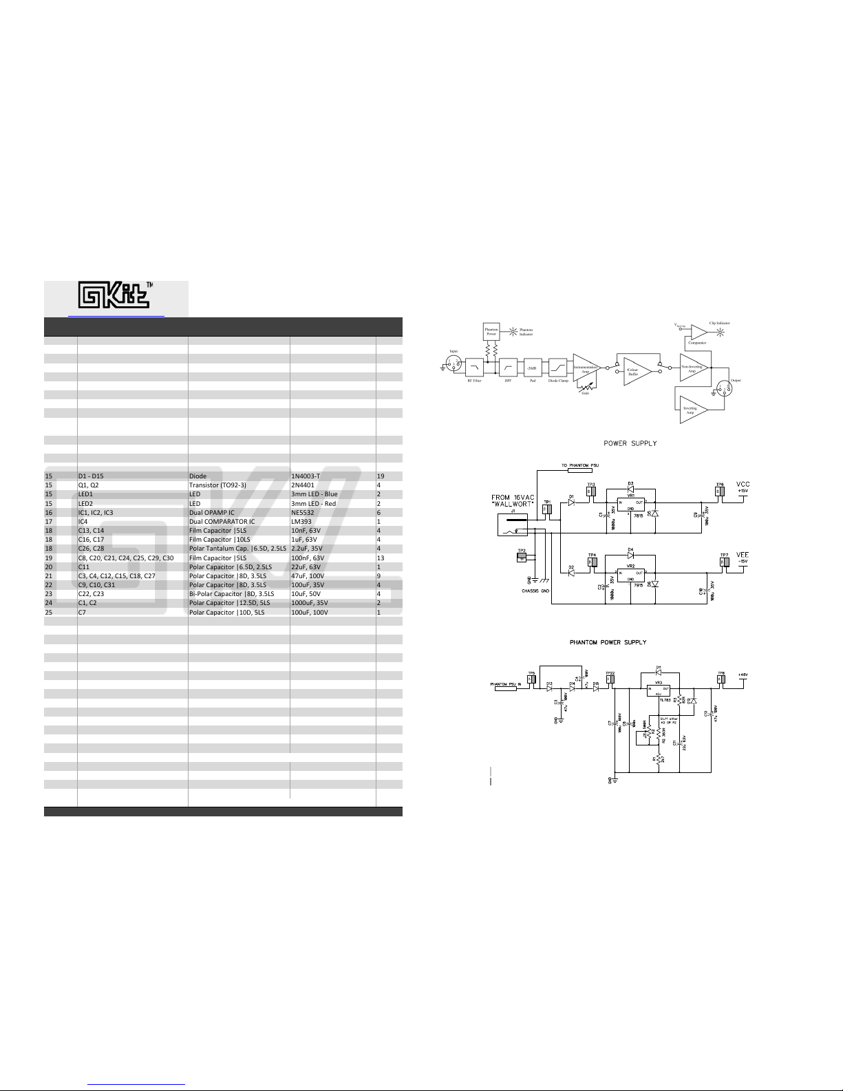
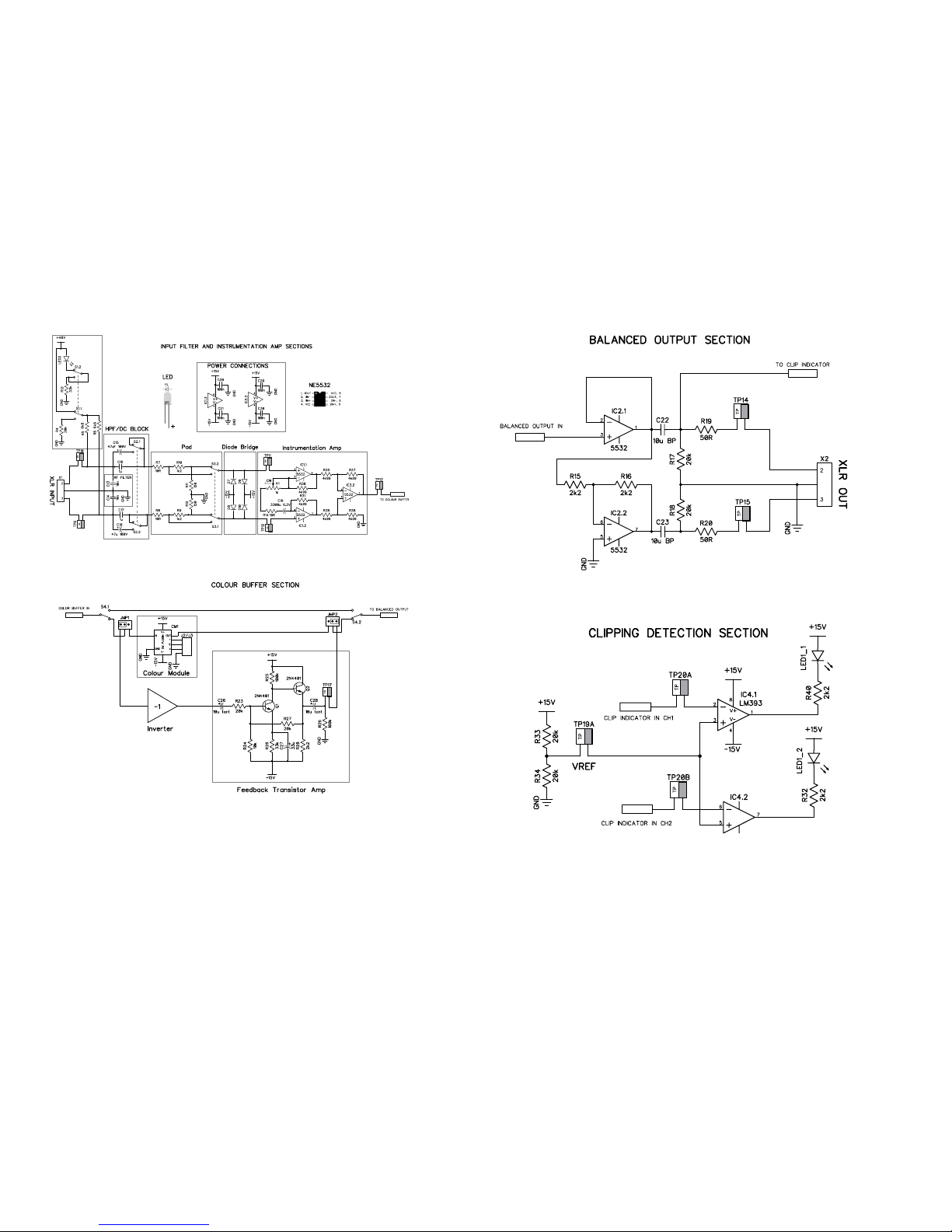
Schematics
Signal Flow Diagram
Bag
Number
Designator Type Value/Model# Qty.
! "! !#$%&"'()(*+, $-.&/ !
$ "$ !#0%&"'()(*+, 121&/ !
1 "1 !#0%&"'()(*+, 2$&/ !
0 "03&"!.3&"!23&"$13&"$.3&"10 !#0%&"'()(*+, $4-&/ !$
5 "53&"6 !#0%&"'()(*+, 6-2&/ 0
6 ".3&"23&"!0 !#0%&"'()(*+, !4&/ 6
. "73&"!4 !#0%&"'()(*+, !-$&/ 0
2 "!!3&"!$ !#0%&"'()(*+, !54&/ 0
7 "!13&"$6 !#0%&"'()(*+, 11-&/ 0
!4
"!53&"!63&"$!3&"$$3&"$23&"1$83&"173&
"0489"15&:;)<=
!#0%&"'()(*+, $-$&/ !0
!! "!73&"$4 !#0%&"'()(*+, 07>7&/ 0
!$ "$03&"11 !#0%&"'()(*+, !4-&/ 0
!1 "$53&"$7 !#0%&"'()(*+, !44-&/ 0
!0 "143&"1!3&"153&"163&"1.3&"12 !#0%&"'()(*+, 0-77&/ !$
!5 ?!&@&?!5 ?)+A' !B0441@C !7
!5 D!3&D$ C,EF()(*+,&9CG7$@1= $B004! 0
!5 H>?! H>? 1II&H>?&@&J;K' $
!5 H>?$ H>? 1II&H>?&@&"'A $
!6 L:!3&L:$3&L:1 ?KE;&GMNOM&L: B>551$ 6
!. L:0 ?KE;&:GOMN"NCG"&L: HO171 !
!2 :!13&:!0 P);I&:E<EQ)*+,&R5HS !4FP3&61T 0
!2 :!63&:!. P);I&:E<EQ)*+,&R!4HS !KP3&61T 0
!2 :$63&:$2 M+;E,&CEF*E;KI&:E<U&R6U5?3&$U5HS $U$KP3&15T 0
!7 :23&:$43&:$!3&:$03&:$53&:$73&:14 P);I&:E<EQ)*+,&R5HS !44FP3&61T !1
$4 :!! M+;E,&:E<EQ)*+,&R6U5?3&$U5HS $$KP3&61T !
$! :13&:03&:!$3&:!53&:!23&:$. M+;E,&:E<EQ)*+,&R2?3&1U5HS 0.KP3&!44T 7
$$ :73&:!43&:1! M+;E,&:E<EQ)*+,&R2?3&1U5HS !44KP3&15T 0
$1 :$$3&:$1 J)@M+;E,&:E<EQ)*+,&R2?3&1U5HS !4KP3&54T 0
$0 :!3&:$ M+;E,&:E<EQ)*+,&R!$U5?3&5HS !444KP3&15T $
$5 :. M+;E,&:E<EQ)*+,&R!4?3&5HS !44KP3&!44T !
$6 :!7 M+;E,&:E<EQ)*+,&R!4?3&5HS 1144KP3&6U5T $
$. T"! H)F'E,&T+;*EV'&"'VK;E*+, M+()*)W'&!5T3&!N&#&O:.2!5 !
$. T"$ H)F'E,&T+;*EV'&"'VK;E*+, B'VE*)W'&!5T3&!N&#&O:.7!5 !
$. T"1 H)F'E,&T+;*EV'&"'VK;E*+, M+(U&NAXU3&.44IN&#&CH.21:- !
$. S!3&S$3&S13&S0 ?M?C&S%LC:Y :Z-&MB$$S[BN41D> 2
$. :+;+K,&JK**+F S\)*Q]&:E< %])*' $
$. HMP&Z&MN?&JK**+F( S\)*Q]&:E< J;EQ^ 0
$. MYCO S\)*Q]&:E< "'A $
$2 _! _H"&P'IE;' B'K*,)^&B:1PNNY $
$2 _$ _H"&OE;' B'K*,)^&B:1ONNY $
$2 -! M+*'F*)+I'*',&9!6II&^FK,;'A= !-&/ $
$2 [! N:&M+\',&:+FF'Q*+, M[@4!.? !
$7 %),' !&)FU&\),' !
$7 CN#:O&]'EA', 1&<)F&]'EA', $
$7 CN#:O&[KI<', :+;+K,&I+AK;'&(';'Q*+, $&M)F&[KI<', $
$7 :O! 2@<)F&(+Q^'*&888O+KF*&+F&S+;A',&S)A'&8888 $
14 _H"&SQ,'\( J;EQ^&(';`@*E<)FV 2
14 >FQ;+(K,'&SQ,'\( S);W',&0@04 0
14 -F+a -F+a Y%@-BJ@JH- $
14 -F+a&:E< -F+a&:E< Y%@-BJ:M@b"c $
R&?&9?)EI'*',&)F&IIU=3&HS&9H'EA&S<EQ)FV&)F&IIU=
\\\UV^;EKA)+UQ+I#V^)*@aEad<,'
:+<d,)V]*&e&$4!1@$4!6&@&b-H&NKA)+U&&N;;&,)V]*(&,'(',W'A
Gkit - Baby Pre v4.1 (Dec. 2016)
Bill of Materials
Educational 2Ch. Mic Pre Kit With Clean / Coloured Gain
Page 6
!
Page 7

Policies
Missing Parts: At GKL we do our best to ensure you receive all the parts you
need to assemble your kits. In some cases we may even send extras of
certain parts just in case. Still, we are only human so if you are missing any
components, please contact us at [email protected]
Damaged Parts: If you damage any of the components in the process of
assembling your kit, we can either sell you a replacement part or help you
source your own replacement.
Non-Working Project: If you get to the end of your assembly and you cannot
get your circuit to function properly, email us at [email protected] with
a description of the problem and pictures of the top and bottom of your circuit
board and we will help you troubleshoot the problem.
Project Guarantee and Repairs: We guarantee that you will end up with a
fully functional BabyPre (if built correctly). If you have tried everything,
including contacting us with photos and a description of your problem, you can
send us your circuit board and we will repair it for you. Repairs are done at a
flat rate of $65 USD. You will be responsible for all of the shipping fees so we
recommend you send only the PCB to keep shipping costs down. Please
email us at [email protected] for the most current shipping information
and to let us know that your BabyPre will be coming in for repairs.
Copyright: The GKit - Baby Pre is protected by Copyright © 2013-2016
- GKL Audio. All rights reserved. No part of this manual or the GKit - BabyPre
including, but not limited to, the text, graphics, images, logos, electronic
design and schematics may be modified, reproduced, transmitted, distributed,
publicly displayed or utilized for any commercial purpose, without the
designer's written permission.
Your BabyPre GKit has been inspected by:
Name Date
!
!
 Loading...