

GKB HZ2001 User Manual
!
!
Before operating this unit, please read this manual
thoroughly and retain it for future reference.
User’s Manual
GKB HZ2001 HD-SDI PTZ Camera
3Megapixel Outdoor HD-SDI PTZ Camera
with 20X Optical Zoom Lens

GKB HZ2001 HD-SDI PTZ Camera
!
About this Manual
This user manual is for use with the GKB HZ2001. This document
contains important information and instructions detailing proper
operation and maintenance of GKB HZ2001. Installation
instructions for these cameras are provided separately in the
Installation Guide.
Be aware that GKB HZ2001 must be installed and used in
accordance with the instructions given in this manual. Before
installing or operating the unit, please read all safety notes and
warnings provided in this manual.
GKB HZ2001 is a surveillance device for use in security systems that
assist in the management of security. GKB is not liable nor can be held
responsible for any material loss and/or personal injuries cause by
robbery, fire, natural disaster or problems of any kind resulting from
the use of this device.
Do not dispose this camera as general waste. This product must be treated
as a recyclable product. Contact your local government recycling program or
the supplier of the product to confirm the proper method of disposal.

GKB HZ2001 HD-SDI PTZ Camera
!
Table of Contents
Warning and Precaution
1.! About The Product!........................................................................................................................!2!
1.1.!Features!...............................................................................................................................!2!
1.2.!Functions!.............................................................................................................................!2!
1.3.!Technical Parameters!.........................................................................................................!5!
2.! Installation!....................................................................................................................................!6!
2.1.!DIP Switch Setting!................................................................................................................!6!
2.2.Installation!..........................................................................................................................!7!
2.2.1.! Dimensions!...........................................................................................................!7!
2.2.2.! Brackets and Installation Holes!............................................................................!8!
2.2.3.! Wall Mount Installation!.........................................................................................!9!
2.2.4.! In-ceiling Mount Installation!...............................................................................!12!
2.2.5.! Surface Mount Installation!..................................................................................!16!
2.2.6.! Pole Mount Installation!.......................................................................................!18!
3.! Operation Guide!......................................................................................................................... !19!
3.1.!Operation At Power Up!.....................................................................................................!19!
3.2.How To Use Our Control Keyboard!.................................................................................!20!
3.2.1.! Control Keypad Password And Access!..............................................................!20!
3.2.2.! Control Keypad Command Syntax!.....................................................................!20!
3.2.3.! Control Keypad Command Types!......................................................................!21!
3.3.Select A Camera!...............................................................................................................!21!
3.4.Camera Motions!..............................................................................................................!22!
3.4.1.! Pan And Tilt!.........................................................................................................!22!
3.4.2.! Zoom!...................................................................................................................!23!
3.4.3.! Focus!...................................................................................................................!23!
3.4.4.! IRIS Opening!........................................................................................................!24!
3.4.5.! Preset Positions Programming and Recalling!....................................................!24!
3.5.Function Program Menu!..................................................................................................!25!
3.5.1.! system Information!.............................................................................................!27!
3.5.2.! Display Setup!......................................................................................................!27!
3.5.2.1.! Label Position ....................................................................................... 29!
3.5.3.! Main Programming Menu (Dome Settings 1)!.....................................................!29!
3.5.3.1.! Camera…… ........................................................................................ 30!
3.5.3.2.! Motion……. ......................................................................................... 36!
3.5.3.3.! Power Up…. ........................................................................................ 39!
3.5.3.4.! Presets……. ......................................................................................... 40!
3.5.3.5.! Patterns…… ........................................................................................ 42!
3.5.3.6.! Zones……… ....................................................................................... 43!
3.5.3.7.! Clear Set…… ....................................................................................... 45!
3.5.3.8.! Preset Number ..................................................................................... 45!
3.5.4.! Secondary Programming Menu (Dome Settings 2)!................................ ............!46!
3.5.4.1.! Alarms……. .......................................................................................... 47!
3.5.4.2.! Addr setting. ................................................................................. ……50!
3.5.4.3.! Password… ......................................................................................... 52!
3.5.4.4.! Windows Blanking ............................................................................... 53!
3.5.4.5.! Heater Setting ...................................................................................... 58!
3.5.4.6.! Cruise Setting ....................................................................................... 59!
3.5.4.7.! Tracking Setting ................................................................................... 60!
3.5.4.8.! Time………. ......................................................................................... 64!
3.5.4.9.! Event……… ......................................................................................... 65!
3.5.5.! Dome Label!.........................................................................................................!68!
3.6.Special Control Panel Commands!...................................................................................!69!
4.! Trouble Shooting!........................................................................................................................!70!
5.! Annex!.........................................................................................................................................!71!
5.1.!DIP Switch Chart!................................................................................................................!71!
GKB HZ2001 HD-SDI PTZ Camera
!
)!
Warning and Precaution
Warning
This information is provided to ensure your safety and to prevent loss
either physical or financial. Read carefully before using the product. Read
all sections of this manual where the following marks are shown.
Ignoring this may result in material loss
and/or serious personal injury including
death.
Ignoring this may result in material loss
and/or slight personal injuries.
Do not disassemble.
Precaution
1. Do not drop the camera.
GKB HZ2001 is not designed to resist heavy impact. Handle
with care to avoid damage to sensitive internal components.
2. Do not expose the camera to radioactivity and mount
facing strong light sources. Exposing the camera to
radioactivity or strong light over long periods of time will
damage the camera’s sensor.
3. Do not supply voltage higher than GKB PTZ regulated
voltage.
Before supplying power to your camera, please make sure
the power supply voltage is supported by your camera.
4. Do not install the camera under unstable light
conditions.
Installing GKB HZ2001 in environments with unstable light
conditions may cause the camera to function abnormally.

GKB HZ2001 HD-SDI PTZ Camera
!!
2!
1. About The Product
1.1 Features
! Up to 1080p/30, 1080p/25 video formats;
! HD-SDI video output;
! HD-SDI and CVBS simultaneous output;
! 1/2.8" Exmor CMOS;
! 20X zoom module, D/N, WDR;
! Pan Speed: 0.05º-400º/S, Tilt Speed: 0.03º-240º/S (Preset status);
! Pan Range: 360 º, Tilt Range: -5 º~+93º, auto flip;
! Support auto focus and auto white balance;
! 256 presets;
! Outdoor / indoor installation;
! Alarm function;
! Thunder attack and Electrical surge protection。
1.2 Functions
Time & Event
Event is a whole set of commands for various dates. The camera automatically executes different
actions on different time of weekdays, weekends and holidays. This is very practical for some
routine surveillance works with different applications.
Pelco D Extended
It is a protocol more powerful than regular Pelco D. It gives two-way communication between the
controller and the PTZ: the controller sends commands to the PTZ and also the PTZ sends back the
current device status. In this case, the control is more precise and efficient.
Soft Address
The camera address can be programmed with built-in OSD menu, and the user does not need to
dismount the camera from field or do any screw work.
Wide Dynamic Range (WDR)
A camera is intended to provide clear images even under back light circumstances where intensity
of illumination can vary excessively, when there are both very bright and very dark areas
simultaneously in the field of view. WDR enables the capture and display of both bright areas and
dark areas in the same frame, in a way that there are details in both areas, i.e. bright areas are
not saturated, and dark areas are not too dark.
Day/Night Function
The IR cut filter of camera module inside the camera can be removed by sending special
command, so that the camera can change from color to mono. The picture is clear even if the
illumination is as low as 0.01Lux.
"
Wide Dynamic Range (WDR) and Day/Night are based on the relative modules.
Please refer to technical data.
Proportional Pan
Proportional pan automatically reduces or increases the pan and tilt speeds in proportion to the
zooming times. At telephoto zoom settings, the pan and tilt speeds will be slower for a given
amount of joystick deflection than at wide zoom settings. This keeps the image from moving too
fast on the monitor when there is a large amount of zoom.

GKB HZ2001 HD-SDI PTZ Camera
!!
3!
Auto Flip
When the camera tilts downward and goes just beyond the vertical angle, the camera rotates 180º.
When the camera rotates (flips), the camera starts moving upward as you continue to hold joystick
in the down position. Once you let go of the joystick after the dome rotates, joystick control returns
to normal operation. The auto-flip feature is useful for following a person who passes directly
beneath the camera.
Save/Call Preset
Preset function is that dome saves current horizontal angle and title angle of pan/tilt, zoom and
position parameters into memory. When necessary dome calls these parameters and adjusts
Pan/Tilt/Zoom to that position. User can save and call presets easily and promptly by using
keyboard controller or infrared controller. The camera supports up to 256 presets.
Lens Control
1) Zoom control
User can adjust zoom wide or tele by controller to get desired image.
2) Focus control
System defaults Auto Focus mode, that is, the lens and camera will automatically adjust the focus
to get the best image.
Focus can also be controlled manually from the controller if required. Press Focus Near or Focus
Far key to manually focus. Focus can be manual via keyboard or matrix, please refer to control
keyboard or matrix operation manual for detailed operation. When adjusting position is set with
focus status, it goes back to auto focus.
The camera will NOT auto focus in the following status.
! Target is not in the center of image.
! Targets are in near and far at the same time.
! Target is of strong light object. Such as spotlight etc.
! Target is behind the glass with water drop or dust.
! Target moves too fast.
! Large area target such as wall.
! Target is too dark or vague.
3) IRIS control
System defaults Auto IRIS. Camera can adjust immediately according to the alteration of back
ground illumination so that a lightness steady image can be achieved.
You may adjust IRIS by controller to get required image brightness, and call back Auto IRIS by
controlling the joystick.
Auto White Balance
Camera can automatically adjust white balance (WB) according to the alteration of background
lightness to give a true color image.
Back Light Compensation (BLC)
If a bright backlight presents, the subjects in the picture may appear dark or as a silhouette.
Backlight compensation enhances objects in the center of the picture. The camera uses the center
of the picture to adjust the IRIS. If there is a bright light source outside this area, it will wash out to
white. The camera will adjust the IRIS so that the object in the sensitive area is properly exposed.
Auto Cruise
The preset position is programmed to be recalled in sequence. This feature is called auto cruise.
Up to 30 presets can be saved in each cruise tour.

GKB HZ2001 HD-SDI PTZ Camera
!!
4!
Patterns
A pattern is a saved, repeating, series of pan, tilt, zoom and preset functions that can be recalled
with a command from a controller or automatically by a programmed function (alarm action or
park action or power-up action).
Auto, Random and Frame Scan
Auto Scan: Make the camera scan 360º ranging from the current position.
Random Scan: Make the camera random scan 360º ranging from the current position.
Frame Scan: This feature freezes the scene on the monitor when going to a preset. This allows for
smooth transition from one preset scene to another.
Zones Setting
A zone is a pan area, defined by a left and right limit, on the 360º pan plane. The camera has
eight zones, each with a 6-character label.
Alarms Input
The camera has four alarm inputs, which can be programmed as high, medium or low priority.
When an alarm is received, an input signal to the camera triggers the user-defined action (go to
preset, run pattern, etc.) programmed for the alarm.
Auxiliary Output
An auxiliary output is a programmable signal from the camera back box that can trigger another
device to operate. An auxiliary output is programmable to trigger from an alarm or from a
controller.
Password Protection
The camera features password protection to prevent unauthorized changes to the camera settings.
You can open the System Information and Display Setup Screens, but cannot access any of the
camera Settings menus.
Windows Blanking
A set window can be saved so that it is the only blanked tilt area of the scene. All other parts of the
tilt area of the scene will be visible.
"
Windows blanking is only available for Sony Modules at present.
GKB HZ2001 HD-SDI PTZ Camera
!!
5!
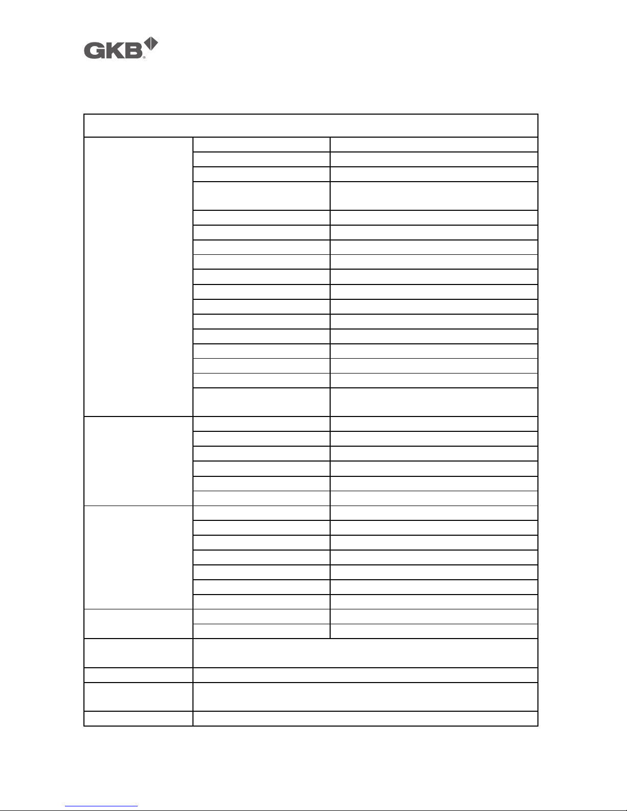
1.3 Technical Parameters
GKB HZ2001 High Speed Dome Camera
Video
Zoom module
Sony FCB-EH6300
Image Sensor
1/2.8” Exmor CMOS Sensor
Number of Effective Pixels
3270K pixels
Lens
20X Optical Zoom (F=1.6~3.5,
f=4.7~94.0mm) 12X Digital Zoom
Focus
Manual, AUTO
Min. working Distance
10mm (Wide) to 1000mm (Tele)
Min. Illumination
0.5 Lux(Color) /0.095 Lux (B/W)
S/N Ratio
More than 50dB
Video Output
HD-SDI, CVBS
Max Frame rate
Up to 30 fps at all resolutions
Digital Shutter
1/1 ~ 1/10,000 Sec
Gain Control
Manual, AUTO
BLC
ON, OFF
Day/Night
Manual, AUTO
WDR
ON, OFF, AUTO
Digital Noise Reduction
ON (1 ~ 5 Programmable), OFF
White Balance
AUTO, Indoor, Outdoor, Auto Track ,
Manual
Pan/Tilt
Pan Range & Speed
360° Endless , 0.05 °~400° /Sec
Tilt Range & Speed
-5 °~93° Auto Flip, 0.03 ° ~240 ° /Sec
Preset Speed
400 ° /Sec (Pan), 240° /Sec(Tilt)
System Accuracy
Approx. 0.1 °
Presets
256
Auto Cruise
1~30 presets in order to switch
Functions
Privacy Mask
8 areas
Manual Language
English / Chinese
Alarm Input & Output
4 In & 2 Out
Communication
RS-485
Address range
0~255
Protocol
PELCO-D / PELCO-P
Baud Rate
2400bps / 4800bps / 9600bps
Power
Power Supply
AC 24V / DC 24V
Power Consumption
20W (Heater OFF) / 50W (Heater ON)
Ingress Protection
Rating
IP66
Dimensions/Weight
4.5 kg (With Wall Mount)
Operating
Temperature
-40 °C ~+55°C (with Heater ON)
Humidity
≤95% , No Condensation
GKB HZ2001 HD-SDI PTZ Camera
!!
6!
2. Installation
This section contains detailed instructions for installing the camera. These instructions assume that
the installer has a good knowledge of installation techniques and is capable of adopting safe
installation methods.
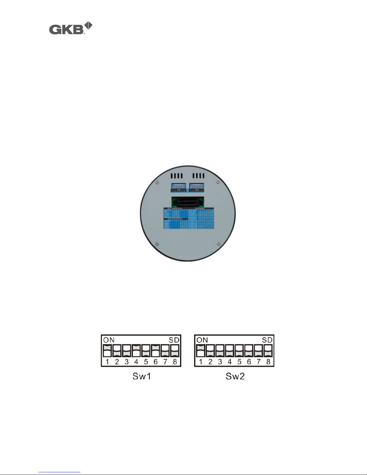
2.1 DIP Switch Setting
Before installing the camera drive, check the DIP switches; SW1 configures communication protocol,
baud rate, and video output format. SW2 configures camera address. Pic. 1 shows switches
position and default settings.
Pic. 1 Switch Position
The default setting is:
Camera Address: 1
Baud Rate: 2400BPS
Protocol: Pelco D
Video format: 720P/50FPS
Pic. 2 Default Setting of DIP Switch
Please refer to Table 32: SWITCH1 SETTING and Table 33: SWITCH2 SETTING in Section 0 to set
baud rate, and communication protocol type and camera address.
"
Do not use address “0” with the “PELCO P” or “PELCO D” protocols.
GKB HZ2001 HD-SDI PTZ Camera
!!
7!
2.2 Installation
The camera has four types of mountings: wall mount, in-ceiling mount, surface mount, and pole
mount. Please make sure which type you are installing.
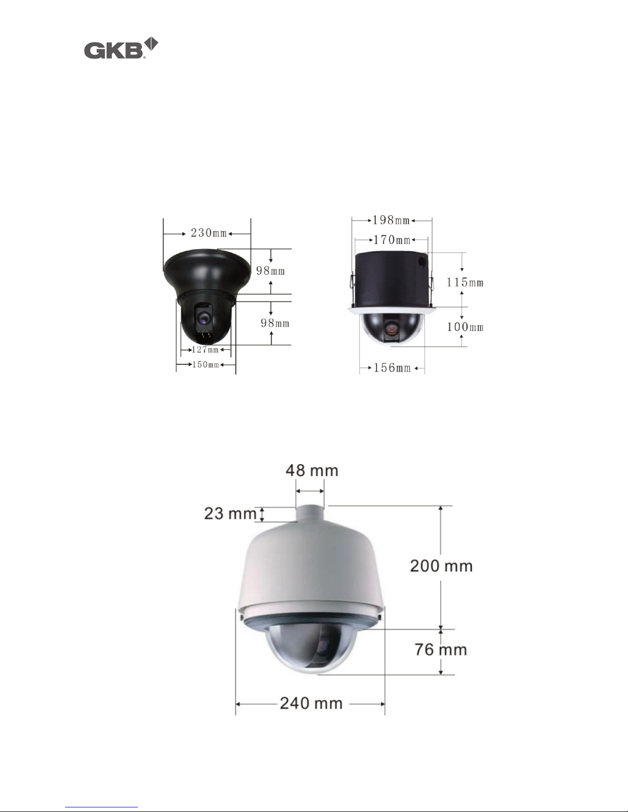
2.2.1 Dimensions
Ceiling Mount In-Ceiling Mount
Wall and Pole Mounts
GKB HZ2001 HD-SDI PTZ Camera
!!
8!
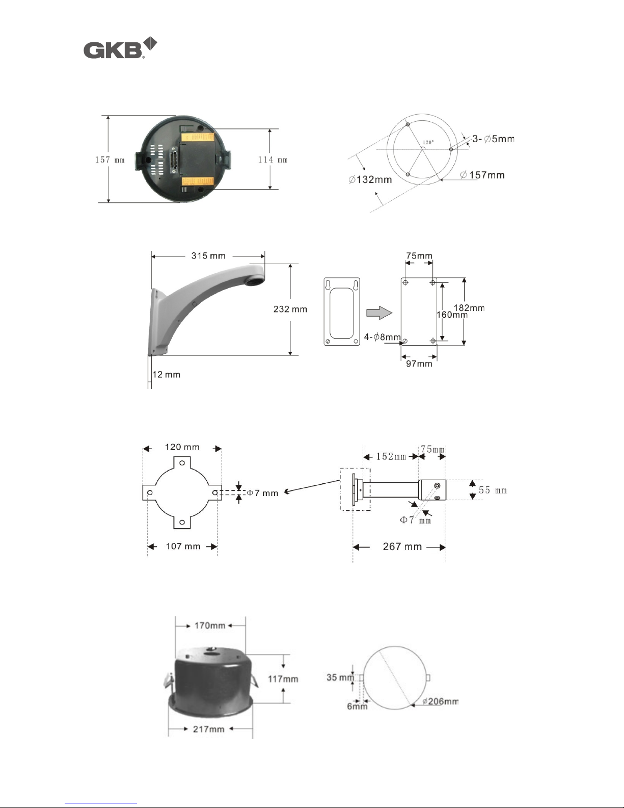
2.2.2 Brackets and Installation Holes
Base Installation Holes of Ceiling Mount
Wall Bracket Installation Holes for Wall Bracket
Pole Bracket and Installation Holes
In-ceiling Mount and Installation Holes
GKB HZ2001 HD-SDI PTZ Camera
!!
9!
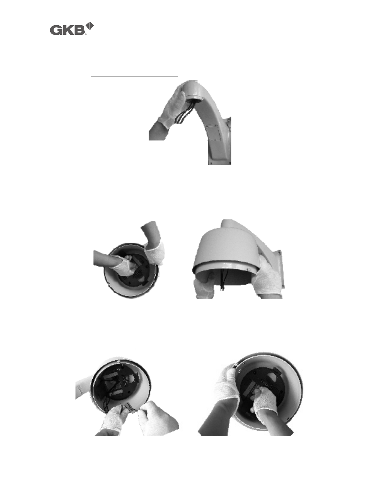
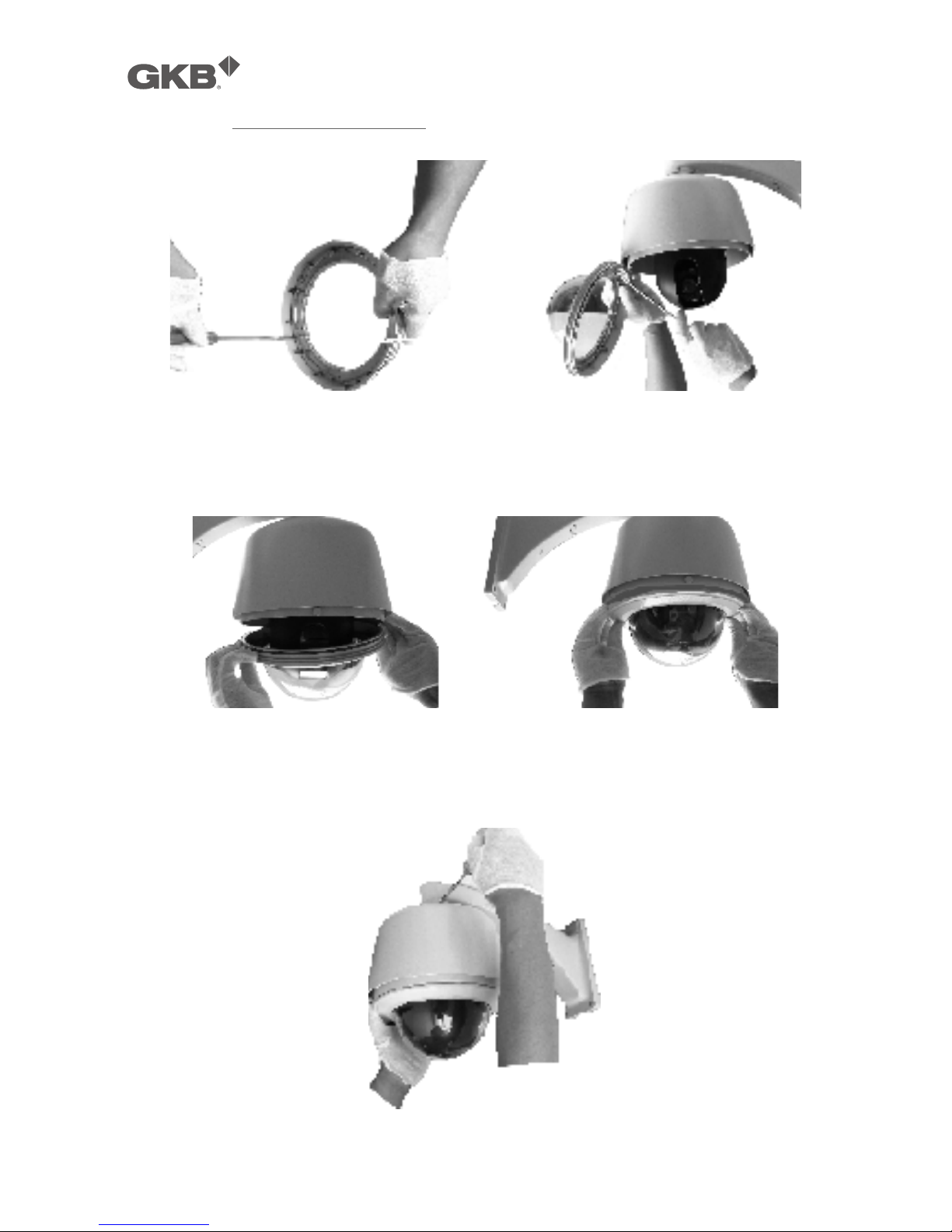
2.2.3 Wall Mount Installation
Step 1. Install bracket on wall
Pic. 3
Refer to the instructions supplied with the bracket. Take out cables for the dome through the
bracket. And install the bracket to the wall. See Pic. 3
Pic. 4
Press the thumb fastener and open the hinged door to the back box. Take out hole of pin. Screw
the metal cover into the bracket. See Pic. 4.
Pic. 5
GKB HZ2001 HD-SDI PTZ Camera
!!
10!
Connect cables to hole of pin. Insert the pin inside the back box. When finished, close the door to
the back box and turn on the power. The LED will light up. See Pic. 5.
"
If the LED does not light up, refer to Section 0: 4. Trouble
Shooting
.
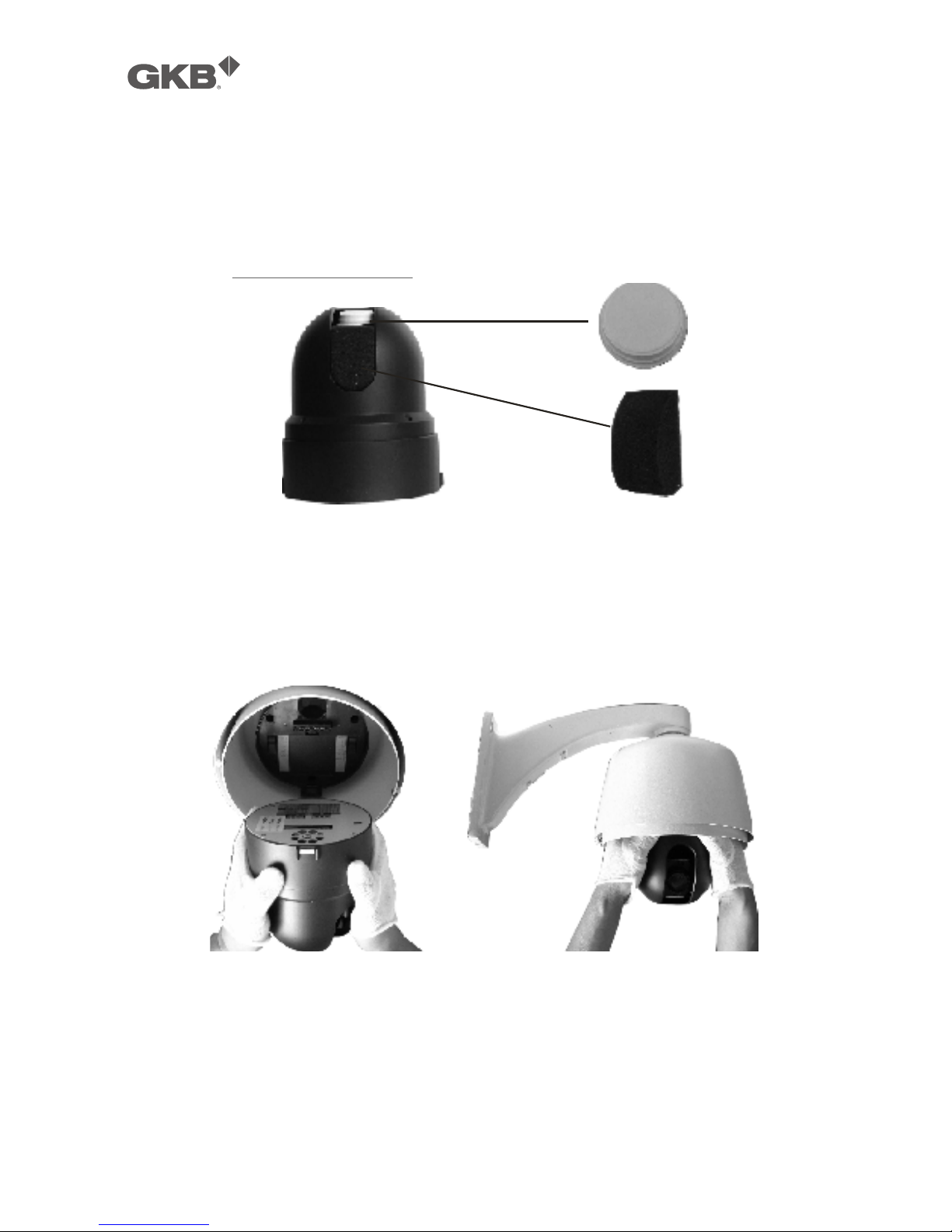
Step 2. Install dome drive
Pic. 6
Set the DIP switches for SW1 and SW2 at the bottom of the dome drive for the appropriate receiver
address, communication protocol, and baud rate. Refer to the labels on the dome drive or DIP
SWITCH SET at the beginning of this manual.
Remove cover of camera and sponge. See Pic. 6.
Pic. 7
Line up link card and faucet of the back board of the dome. Push the dome drive in. See Pic. 7.
GKB HZ2001 HD-SDI PTZ Camera
!!
11!
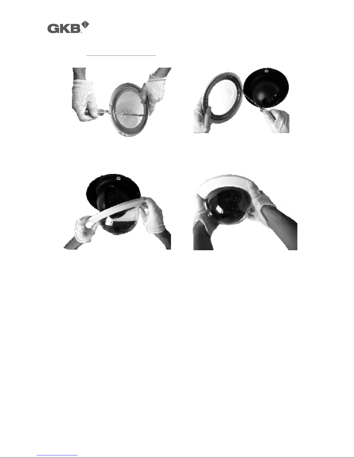
Step 3. Install lower dome.
Pic. 8
Take out a screw from lower dome. Link cables, screw, and lower dome. See Pic. 8.
Pic. 9
Line up the mounting screw holes, and install the two mounting screws. Push the lower dome
inside the back box. See Pic. 9.
Pic. 10
Screw the two mounting screws, and screws in the bracket. See Pic. 10.
GKB HZ2001 HD-SDI PTZ Camera
!!
12!
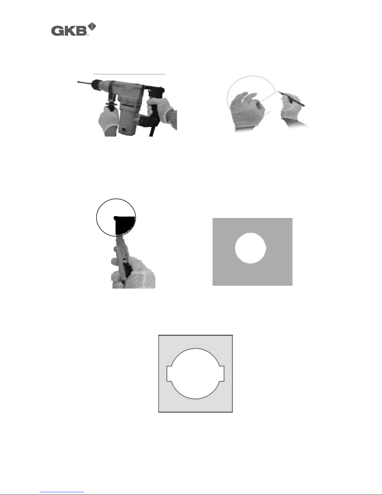
2.2.4 In-ceiling Mount Installation
Step 1. Prepare In-ceiling
Pic. 11
Locate the center point of the in-ceiling mounting location. Insert the compass tool into the hole.
Draw a circle on the ceiling using the compass tool and a pencil. See Pic. 12 (Left).
Cut the circle out of the ceiling tile. See Pic. 12 (Right).
Pic. 12
Put the reinforcing metal plate (see following pic.) on top of the ceiling (behind the ceiling) with the
two circles aligned vertically.
Pic. 13
GKB HZ2001 HD-SDI PTZ Camera
!!
13!
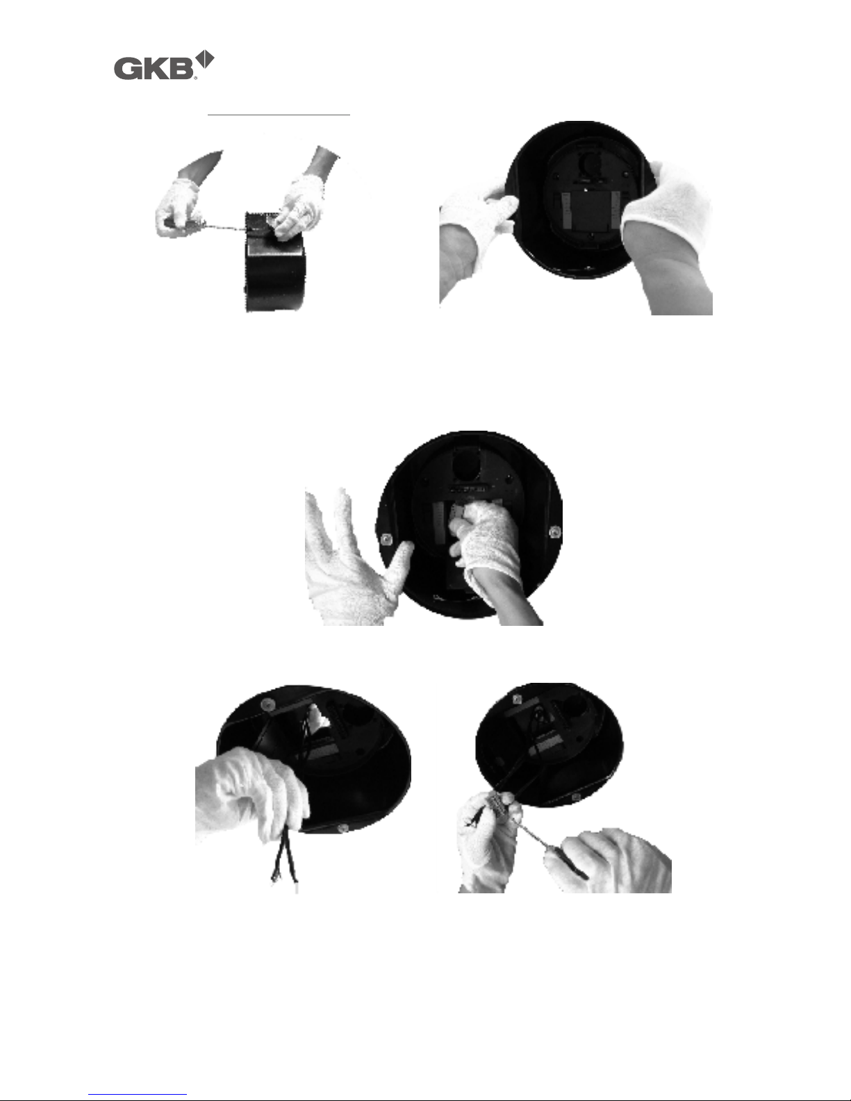
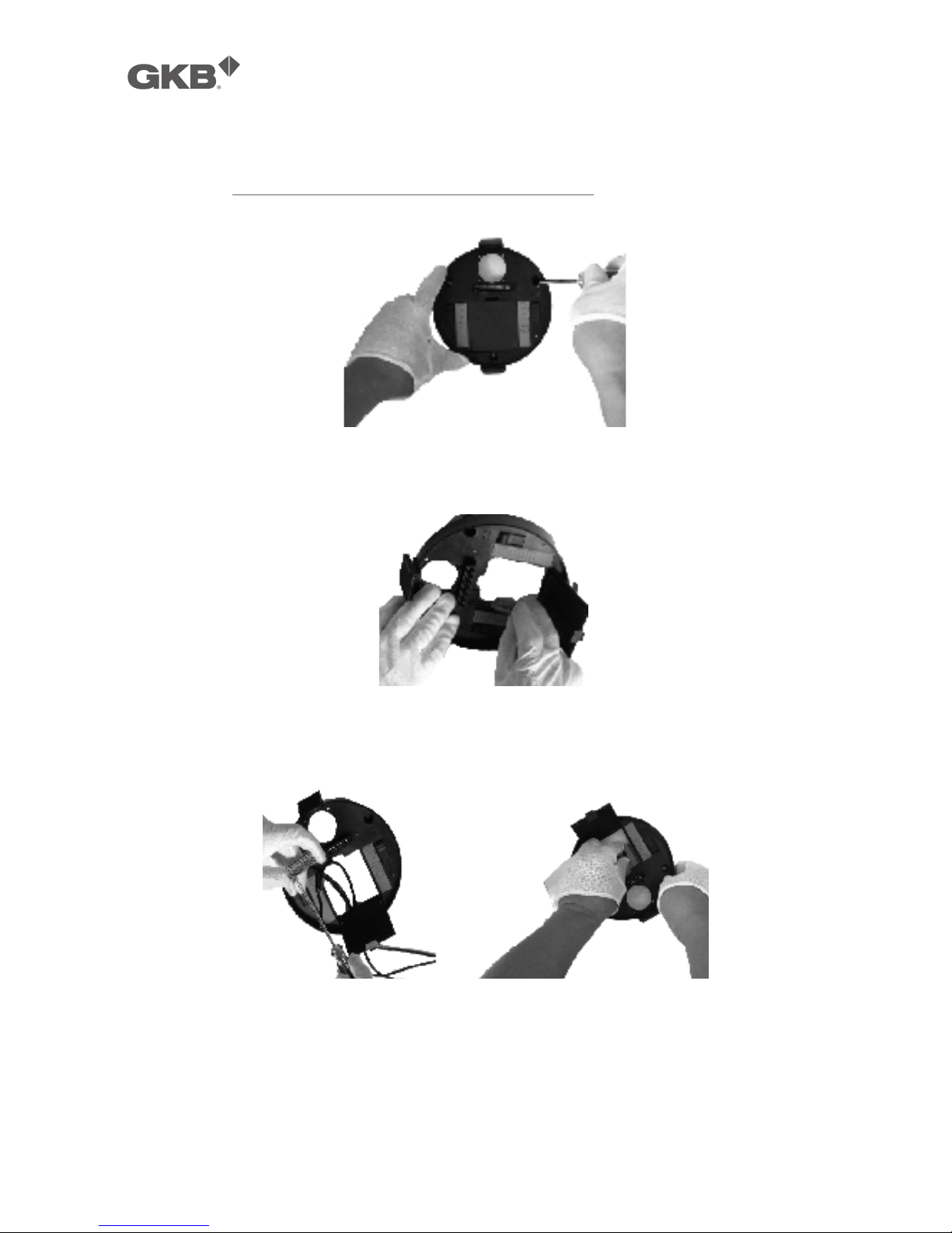
Step 2. Install back box
Pic. 14
Take out bracket from back box. Insert the back box into ceiling. See Pic. 14.
Install a safety chain/cable (not supplied) that can stand up to 32 pounds (14.6kg). Press the thumb
fastener and open the hinged door to the back box. Take out hole of pin. See Pic. 15
Pic. 15
Pull cables into the back box through the plastic panel. Connect cables to hole of pin. See Pic. 16
Pic. 16
Insert the hole of pin inside the back box. When finished, close the door to the back box and turn
on the power. The LED will light up. See Pic. 17.
GKB HZ2001 HD-SDI PTZ Camera
!!
14!
Pic. 17
"
If the LED does not light up, refer to Section 0: 4. Trouble
Shooting
.
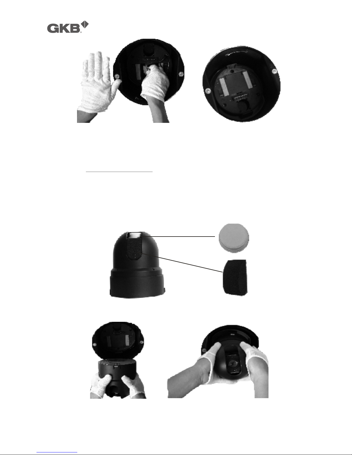
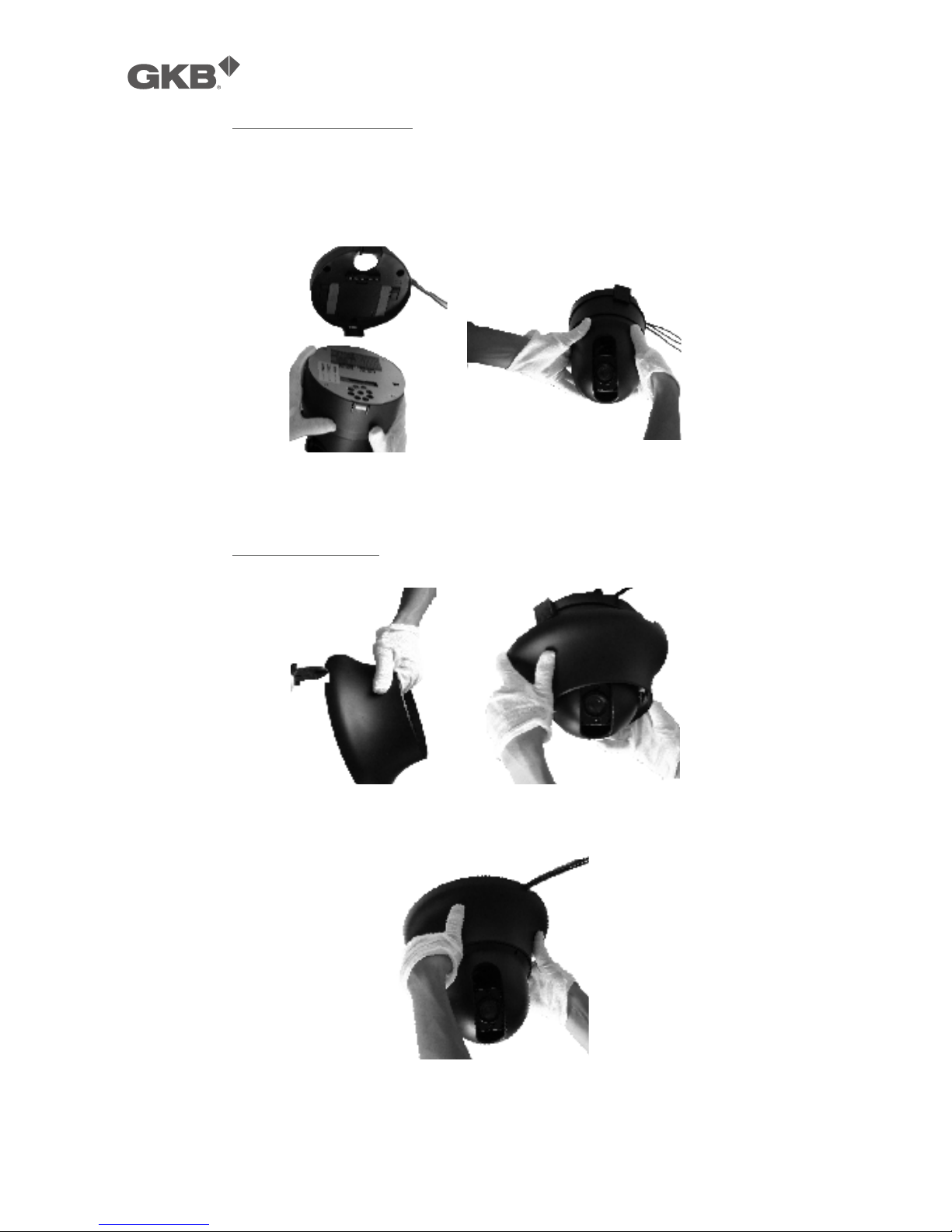
Step 3. Install dome drive
Set the DIP switches for SW1 and SW2 at the bottom of the camera drive for the appropriate
receiver address, communication protocol, and baud rate. Refer to the labels on the camera drive
or DIP SWITCH SET in this manual.
Remove cover of camera and sponge. See Pic. 18
Pic. 18
Line up link card and faucet of the back board of the dome. Push the dome drive in. See Pic. 19
Pic. 19
GKB HZ2001 HD-SDI PTZ Camera
!!
15!
Step 4. Install lower dome
Pic. 20
Take out a screw from lower dome. Link cables, screw, and lower dome. See Pic. 20.
Pic. 21
Line up the snaps on trim ring with the mounting screws on the back box. Snap the trim ring into
the plastic snap washers on the mounting screws. See Pic. 21.
GKB HZ2001 HD-SDI PTZ Camera
!!
16!
2.2.5 Surface Mount Installation
Step 1. Install back board of surface mount
Pic. 22
Locate the back board of the camera location. Drill a hole in the ceiling using a drill. Insert the
screw and back board into the hole. See Pic. 22
Pic. 23
Press the thumb fastener and open the hinged door to the back box. Take out hole of pin. See Pic.
24.
Pic. 24
Pull cables into the back box into the plastic panel. Connect cables to hole of pin. Insert the hole of
pin inside the back board. When finished, close the door to the back board and turn on the power.
The LED will light up. See Pic. 24.
"
If the LED does not light up, refer to Section 0: 4. Trouble
Shooting
.
GKB HZ2001 HD-SDI PTZ Camera
!!
17!
Step 2. Install dome drive
Set the DIP switches for SW1 and SW2 on the bottom of the dome drive for the appropriate receiver
address, communication protocol, and baud rate. Refer to the labels on the dome drive or DIP
SWITCH SET in this manual.
Pic. 25
Line up link card and faucet of the back board of the dome. Push the dome drive in. See Pic. 25.
Step 3. Install dome flange
Pic. 26
Snip a flake piece. Keep three flanges away from two clamps on the back board. See Pic. 26.
Pic. 27
Push the flange of dome into the back board. Take out the membrane on the clarity flake of the
dome drive. See Pic. 27.

GKB HZ2001 HD-SDI PTZ Camera
!!
18!
2.2.6 Pole Mount Installation
See Section 0 2.2.3 Wall Mount Installation.

GKB HZ2001 HD-SDI PTZ Camera
!!
19!
3. Operation Guide
3.1 Operation At Power Up
The camera employs the default settings the first time it is switched on. Changes to the settings will
be permanently stored and will be made available the next time the camera is switched on. You
can return to the default settings by means of the appropriate menu option at any time.
The camera will work as follows when it is switched on.
The camera will run a calibration procedure and a message showing the following information
will appear on the video output OSD (On Screen Display): protocol, communication parameters,
camera address and software version.
Check that the data are suitable for operation. Otherwise, refer to the section in this document that
shows how to install the camera correctly.
At the end of the calibration step, the camera will switch to stand-by as programmed (POWER UP
ACTION in DOME SETTINGS1 > POWER UP). The camera will continue working this way until any
command is received from controller. The camera during this phase can be pointed to a fixed
point or pan across the field. Refer to the detailed described in the POWER UP ACTION menu
section for more details.
!"#$%&!'$(#)*&
(#++%&,-../&0/&1/&2&
3**4%&2&
5#6"734'&8'459#0&&&82:.:2&
GKB HZ2001 HD-SDI PTZ Camera
!!
20!
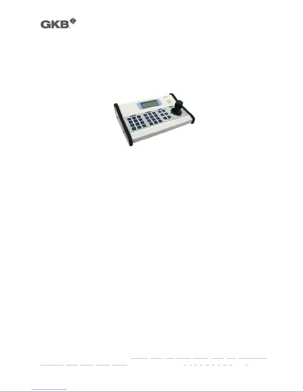
3.2 How To Use Our Control Keyboard
The camera is ready to receive commands from our control keyboard (see figure below) after
connecting.
"
Besides our control keyboard, the PTZ camera also accepts other standard control
devices with Pelco D/P or other accepted protocols.
"
This manual is based on our control keyboard. In case other control devices, please
refer to the manual of the control device for the command syntax.
3.2.1 Control Keypad Password And Access
The system will wait for the password to be entered after being switched on.
The control panel requires a 6-digit password.
The entered digits will be replaced by a “*” symbol on the screen for privacy.
Access to the menu is gained after entering all the digits correctly.
Refer to the corresponding manual for using the control panel.
"
The default user password is “000000”.
"
It is advisable to change the default password to prevent intrusions.
"
Do not lose or forget the programmed password.
"
Take note of the new password and keep it in a safe place.
3.2.2 Control Keypad Command Syntax
Controls can use the joystick, single keys or key combinations. The key command syntax is shown
below.
Key command syntax
The syntax used in this manual for controls using keys consists of various elements (words and
three digit numbers). Each command is always in braces and each element is separated by
commas. Each word or decimal digit used in the syntax is identified by a corresponding key on our
control panel. Words can be enclosed in round brackets, square brackets or no brackets. Three
digit decimals are never enclosed in brackets.
The following words only can be used: PRESET, CALL, ESC, OPEN, CLOSE, NEAR, FAR, ZOOM OUT,
ZOOM IN, CAM, MON, SCAN, ENTER. The decimal digits are: 0, 1, 2, 3, 4, 5, 6, 7, 8, and 9.

GKB HZ2001 HD-SDI PTZ Camera
!!
21!
Some application examples of controls are shown in detail below.
Using the joystick
A command can also be given simply by moving the joystick because this generates actions on
the camera or OSD (On Screen Display) menu.
Using a single key
Pressing a single key can cause camera action. For example, the following command will zoom
out of the frame. Underling indicates the key is in use.
ZOOM OUT
Key combinations
Pressing a key combination in rapid sequence extents the command set. For example, the
following command (select camera address 1) is performed by pressing the following keys:
CAM + 1 + ENTER
3.2.3 Control Keypad Command Types
There are four command types:
! Select camera,
! Move camera (tilt and pan, zoom, adjust focus and IRIS opening, go to preset positions),
! Adjust camera operation mode using menus,
! Various quick controls operable from the control panel.
The method for accessing these controls will be shown in detail in the following paragraphs.
3.3 Select A Camera
The camera to be controlled must be selected first. For example, the following command selects
camera 1:
CAM + 1 + ENTER
After this operation, the message CAM 1 will appear on the control panel display.

GKB HZ2001 HD-SDI PTZ Camera
!!
22!
3.4 Camera Motions
After selecting a camera, it can be moved either directly using the control panel as described
below:
! Panning (horizontal) and tilting (vertical).
! Zooming, focusing and IRIS opening.
! Preset positions programming and recalling.
These functions can be directly accessed using a single key or joystick or a simple key combination.
3.4.1 Pan And Tilt
The camera may be moved using our keyboard controller. Move the joystick vertically to tilt the
camera and horizontally to pan it.
The maximum pan span is from 0º to 360º with continuous rotation. The maximum tilt span is from
-5º (camera in vertical position) and 92º.
The panning and tilting speed can be modulated by operating the joystick appropriately.
Note that the maximum speed that can be obtained by operating the joystick is not always equal
to that programmed in the working settings. This in fact depends on the value of the
PROPORTIONAL PAN setting in the MOTION menu and the zoom. If the option is ON, the
maximum rotation speed which can be obtained using the joystick is proportional to the
magnification used to obtain the best frame.
Panning (horizontal)
Tip the joystick rightwards to turn the camera horizontally clockwise and tip it leftwards to turn it
anticlockwise.
If no advanced options are set (e.g. range limits set enabled), the camera can be turned
continuously without interruptions.
The pan span may be limited between two angles in DOME SETTING1 > MOTION > MANUAL
LIMIT.
Tilting (vertical)
Tip the joystick upwards to turn the camera vertically upwards and tip it downwards to turn the
camera downwards. The camera rotation is limited upwards by the horizontal plane or
downwards by the vertical axis.
Performance will change considerably near the vertical axis according to whether the AUTO FLIP is
on or not (default setting is on).
! With AUTO FLIP off, the camera will stop in perfectly vertical position and will stop turning
when the joystick is tipped downwards.
 Loading...