

GKB 4CH, 8CH User Manual
GKB 4CH/8CH VFIRE Server
Onvif Network Recorder
Before operating this unit, please read this manual
thoroughly and retain it for future reference.
User’s Manual

GKB 4CH/8CH VFire Server
2
CAUTION
TO REDUCE THE RISK OF ELECTRIC SHOCK, DO NOT REMOVE COVER.
NO USER SERVICEABLE PARTS INSIDE.
PLEASE REFER SERVICING TO QUALIFIED SERVICE PERSONNEL.
NOTE: This equipment has been tested and found to comply with the limits for a
Class “A” digital device, pursuant to Part 15 of the FCC Rules. These limits are
designed to provide reasonable protection against harmful interference when the
equipment is operated in a commercial environment. This equipment generates,
uses and can radiate radio frequency energy and, if not installed and used in
accordance with the instruction manual, may cause harmful interference to radio
communications. Operation of this equipment in a residential area is likely to
cause harmful interference in which case the users will be required to correct the
interference at their own expense.
FCC Caution: To assure continued compliance, use only shielded interface cables
when connecting to computer or peripheral devices. Any changes or
modifications not expressly approved by the party responsible for compliance could
void the user’s authority to operate this equipment.
This Class A digital apparatus meets all the requirements of the Canadian
Interference Causing Equipment Regulations.
WARNING
TO PREVENT FIRE OR ELECTRIC SHOCK HAZARD, DO NOT EXPOSE THIS APPLIANCE TO RAIN
OR MOISTURE.

GKB 4CH/8CH VFire Server
3
LIMITATION OF LIABILITY
n THIS PUBLICATION IS PROVIDED “AS IS” WITHOUT WARRANTY OF ANY KIND, EITHER
EXPRESS OR IMPLIED, INCLUDING BUT NOT LIMITED TO, THE IMPLIED WARRANTIES
OF MERCHANTIBILITY, FITNESS FOR ANY PARTICULAR PURPOSE, OR
NON-INFRINGEMENT OF THE THIRD PARTY’S RIGHT.
n THIS PUBLICATION COULD INCLUDE TECHNICAL INACCUACIES OR TYPOGRAPHICAL
ERRORS. CHANGES ARE ADDED TO THE INFORMATION HEREIN, AT ANY TIME, FOR
THE IMPROVEMENTS OF THIS PUBLICATION AND/OR THE CORRESPONDING
PRODUCT(S).
DISCLAIMER OF WARRANTY
IN NO EVENT SHALL THE SUPPLIER BE LIABLBE TO ANY PARTY OR ANY PERSON, EXCEPT
FOR REPLACEMENT OR REASONABLE MAINTENANCE OF THE PRODUCT, FOR THE CASES,
INCLUDING BUT NOT LIMITED TO THE FOLLOWINGS:
n ANY DAMAGE OR LOSS, INCLUDING BUT WITHOUT LIMITATION, DIRECT OR INDIRECT,
SPECIAL, CONSEQUENTIAL OR EXEMPLARY, ARISING OUT OF OR RELATING TO THE
PRODUCT;
n PERSONAL INJURY OR ANY DAMAGE CAUSED BY INAPPROPRIATE USE OR
NEGLIGENT OPERATION OF THE USER;
n UNAUTHORIZED DISASSEMBLE, REPAIR OR MODIFICATION OF THE PRODUCT BY THE
USER;
n ANY PROBLEM, CONSEQUENTIAL INCONVENIENCE, OR LOSS OR DAMAGE, ARISING
OUT OF THE SYSTEM COMBINED WITH THE DEVICES OF THE THIRD PARTY;
n ANY CLAIM OR ACTION FOR DAMAGES, BROUGHT BY ANY PERSON OR
ORGANIZATION BEING A PHOTOGENIC SUBJECT, DUE TO VIOLATION OF PRIVACY
WITH THE RESULT OF THAT SURVEILLANCE-CAMERA’S PICTURE, INCLUDING SAVED
DATA, FOR SOME REASON, BECOMES PUBLIC OR IS USED FOR THE PURPOSE OTHER
THAN SURVEILLANCE.

GKB 4CH/8CH VFire Server
4
PRECAUTIONS
n Please refer all work related to the installation of this product to qualified service
personnel or system installers.
n Do not operate the appliance beyond its specified temperature, humidity or power
source ratings.
Use the appliance at temperature within 0oC ~ +40oC (32oF ~ 122oF) and humidity
below 85%.
The input power source for this appliance is +12VDC (and +48VDC for PoE).
Performance and lifetime of hard disk drives are easily affected by heat (used at
high temperature). It is recommended to use this appliance at temperature
within +20oC ~ +30oC (68oF ~ 86oF)
n Handle the hard disk drives with care.
It is possible to damage them if they are moved while their motors are still running.
Do not move them just after turning the power on or off (for around 30 seconds).
Protect the hard disk drives from static electricity.
Do not stack them or keep them upright.
Do not use an electric screwdriver to fix them.
n Clean only with dry cloth.
n Do not block any ventilation openings.
n Do not use the appliance near any heat sources such as radiators, heat registers,
stoves or other apparatus that produce heat.
n Protect the power cord from being stepped on or pinched particularly at plugs,
convenient receptacles and the points where they exit from the apparatus.
n Do not drop metallic parts through slots. This could permanently damage the
appliance. Turn the power off immediately and contact qualified service
personnel for service.
n Handle the appliance with care. Do not strike or shake, as this may damage the
appliance.
n Do not expose the appliance to water or moisture, nor try to operate it in wet
areas. Do take immediate action if the appliance becomes wet. Turn the power
off and refer servicing to qualified service personnel. Moisture may damage the
appliance and also cause electric shock.
n Do not use strong or abrasive detergents when cleaning the appliance body.
When the dirt is hard to remove, use a mild detergent and wipe gently.
n Do not overload outlets and extension cords as this may result in a risk of fire or
electric shock.
n Please make a note of your settings and save them. This will help when you are
required to change the system configuration, or when unexpected failure or
trouble occurs.
n Distributing, copying, disassembling, reverse compiling, reverse engineering, and
also exporting in violation of export laws of the software provided with this product,
is expressly prohibited.

GKB 4CH/8CH VFire Server
5
Table of Contents
1. Product Overview………………….……………………….……...
1.1 Features…………………..…….…………..…………………...
2. Panels And Remote Controller…………...………………….…….
2.1 Front Panel………….……….…………………………….…….
2.2 Back Panel………………….…………………………….……..
2.3 Remote Controller…………..…….……………………….……
3. Installations…….…….……………………………………….……
3.1 Basic Connections…………….………………………….……..
3.2 Optional Connections…………..………………………….……
4. Main Screen And Basic Operations………….……..……….…...
4.1 Text Input……………………………………….………………
4.2 Login And Logout………………………………………………
4.3 Basic Operations…………………………….…………………
4.4 Digital Zoom…….………………………….………….………
5. Menu Display………..……..………………………………….…...
5.1 Status Display….……………………………….………………
5.2 Volume Control…………..……………..……………..………
5.3 Video Adjustment…………..……………..……………..……
5.4 Display……………..…………………..………………………
5.5 Backup Device……………..……………..……………………
5.6 Software Upgrade (Administrator) ……………………………
5.7 System Shutdown (Administrator)……………….……………
6. Setup (Administrator)………………..….………………………...
6.1 Pre-Camera Setup…………………..….………………………...
6.2 Camera Setup……………………………………………………
6.2.1 Video Loss Setup…………………..………………………
6.2.2 Motion Setup……………………….………………………
6.3 Alarm Setup………………….…..…………………….……….
6.4 Main/SEQ Display Setup………………………………………
6.5 Scheduled Record Setup……………..…….………….…………
6.6 HDD Setup………………………………………………………
6.6.1 HDD Format/Clear………………..……………………….
6.6.2 Advanced HDD Setup……………..……………………….
6.7 Password Setup……………………………..…………………..
6.8 System Setup…………...………………………………………
6.9 RS-232/485/IR Setup…………..…………………….………..
6.10 Network Setup……………..…………………………………..
7
7
9
9
10
12
15
15
17
19
20
21
21
23
25
26
27
27
29
30
32
33
34
35
37
40
41
45
48
50
53
55
58
60
64
66
68

GKB 4CH/8CH VFire Server
6
6.10.1 Notification Setup……………..…………………………..
6.10.2 FTP Setup……………..…………………………………..
6.10.3 3G Modem Setup…………….. .. .. .. ..…………………
6.10.4 Advanced Network Setup……………..…………………
7. PTZ Control……………………….………………………………
8. Search/Playback/Archive (Administrator/Supervisor) ………....
8.1 Search By Time……………………………………….…………
8.2 Search By Event / Log Display………………………….………
8.3 Search Archived Files………………………….……….………
8.4 POS Search…………………………………….……….………
8.5 Playback/Archive For Search By Time………….….….………
8.6 Playback/Archive For Search By Event…………………………
8.7 Playback For Archived Files……………………………………
8.8 Playback/Archive For POS Search……………………………
9. Remote Access …………………………………………………..…
9.1 PC Remote Access…………………………………….…………
9.2 PDA/Mobile Phone Remote Access…………………….………
Appendix A – Specifications
Appendix B – Time Zone Table
Appendix C – Keyboard Control Protocol
Appendix D – MS-Windows HEM Utilities
Appendix E – GPS Function in Remote Software with Google Earth
Appendix F – Protocol Converter for Multiple POS
Appendix G – VFire Server Operation
71
72
73
75
77
79
80
82
84
85
87
91
92
92
93
93
103
104
106
108
110
115
119
125

GKB 4CH/8CH VFire Server
7
1. Product Overview
The Network video/audio recorders are designed for use within a surveillance
system, and are a combination of a hard disk recorder, a video multiplexer, and a
web server. To achieve the highest inter-connectivity and inter-operability, this
series of network video/audio recorders are all based on industry-leading
front-end to back-end surveillance infrastructure. With state-of-the-art system
architecture, powerful compression/decompression engine, and intelligent
recording algorithms, sixfold operation can be easily achieved without sacrificing
the increasing demands of functionality, performance, reliability, and availability in
the surveillance industry.
1.1 Features
n Up to 8/4-CH 1080p/720p IP-CAM can be connected
n H.264 video compression/decompression with configurable quality
n G.726(ADPCM)/G.711(PCM) audio compression/decompression
n Real sixfold operation - simultaneous record, live, playback, backup, control, &
remote access
n Record capabilities –
IP-CAM: 120fps@1080p, 240/200fps@720p.
n Playback capabilities –
IP-CAM: 80fps@1080p, 160fps@720p.
n Max 56Mbps incoming bandwidth for IP-CAM
n Realtime live display
n Support HDMI output and VGA output
n Support touch panel with USB interface
n Event recording, time-lapse recording or both
n Playback search by time or event (alarm, motion, & video loss)
n Snapshot playback video
n Versatile display formats: full-screen, 4, 7, and 9 split windows
n Digital zoom, X2 & X4
n Motion detection with programmable area and sensitivity
n Powerful alarm processor with configurable triggering conditions and reactions
n Support push alarm notification to mobile phones
n One/two internal 3.5” SATA hard disk drives with storage > 4TB/HDD
n Video/audio backup to USB2.0 storage devices
n Ethernet/USB 3G interface for remote access through web browser or
proprietary remote software, remote alarm notification, FTP video/audio

GKB 4CH/8CH VFire Server
8
storage, remote setup, and remote software upgrade
n Free DDNS server
n Support UPnP, P2P and QR code
n 1 I.E./Firefox software for unlimited number of NVRs
n PTZ control capabilities & RS-485 keyboard control capabilities
n Multi-lingual support
n Multi-level password and authentication key protection to ensure high degree
of security
n Dynamic streaming video for mobile phone or PDA, no Apps required
n Dynamic N-Streaming internet/intranet remote access
n Free iPhone/iPad/Android/Mac software app.
n GPS support
n POS support
n Support mouse operation

GKB 4CH/8CH VFire Server
9
2. Panels and Remote Controller
2.1 Front Panel
1. LEDs
Indicators for POWER, HDD, etc.
2. Remote I/R Sensor
Used to receive signal from I/R remote controller.

GKB 4CH/8CH VFire Server
10
2.2 Back Panel
1. Audio Output Connector (AUDIO OUT)
The connector supplies line-out audio signal to external devices such as
speakers. Recorded audio will be supplied from AUDIO OUT during playback.
2. Audio Input Connectors (AUDIO IN)
The RCA connector accepts line-in audio signals supplied from external devices
such as microphone amplifiers.
3. Main Monitor Output VGA Connector (VGA)
Connect VGA monitor to the optional D-SUB 15-pin female connector for main
monitor display.
4. HDMI Connector
Connect HDMI monitor to the HDMI connector for main monitor display.
5. Ethernet Connector
Connect this unit to a 10/100Base-T Ethernet network through this port. Please
note this connector is useless if PoE module is used (11-14).
6. USB Connectors
Connect to USB 2.0 compatible mouse, pen drive, etc.
GKB 4CH/8CH VFire Server
11
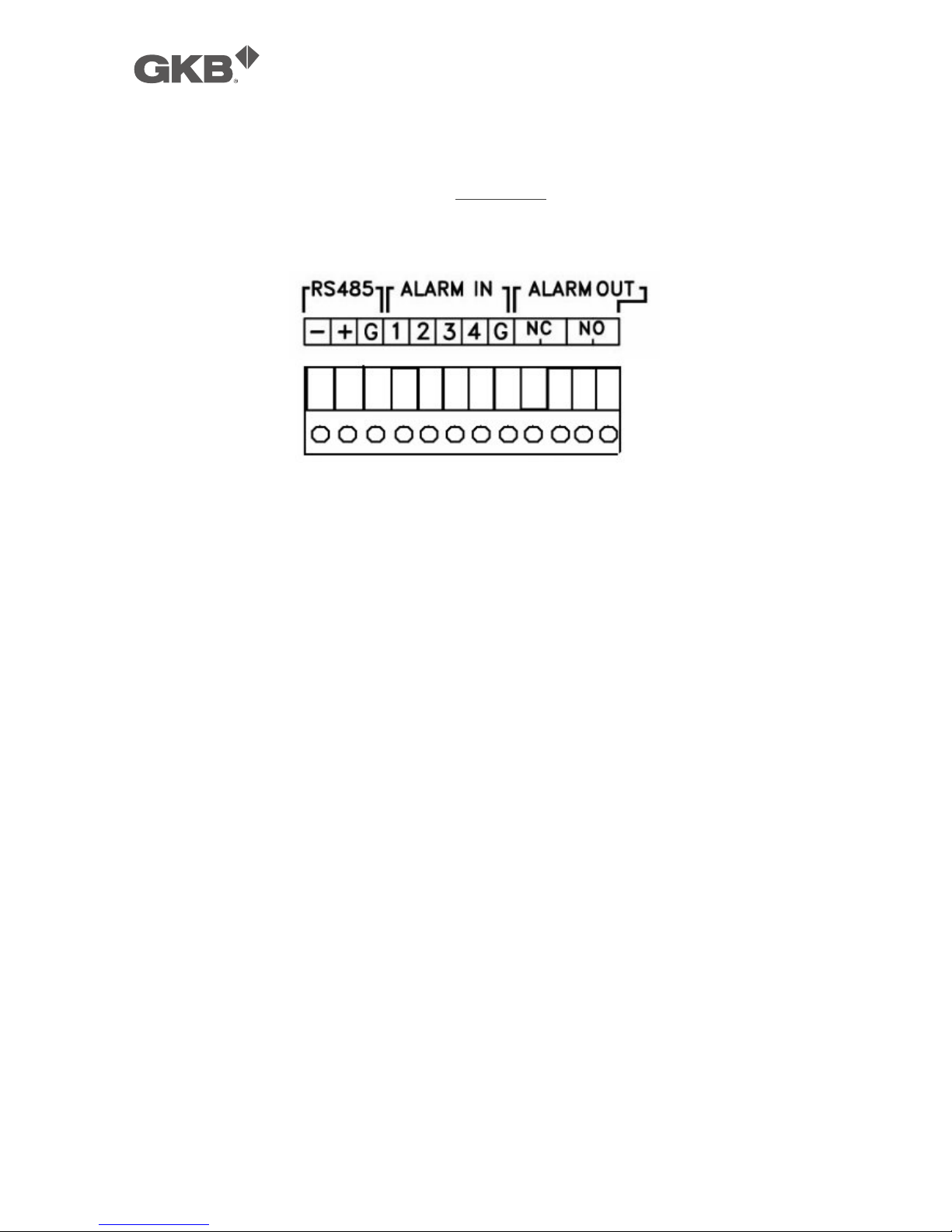
7. RS-485 Connector
Connect this connector to RS-485 compatible PTZ camera(s) or keyboard.
Please refer to the manuals come with the RS-485 compatible devices for the
correct settings. Please refer to Appendix C for the Keyboard Control Protocol
for the network video recorder.
8. Alarm Input Connectors (ALARM IN 1-4)
Connect these connectors to external devices such as sensors or door
switches.
9. Alarm Output Connectors (ALARM OUT NC(1)/NO(2))
Connect NC connectors (left) to Normally Closed (NC) alarm output, or NO
connectors (right) to Normally Open (NO) alarm output. Please note that only
one of the NC or NO connectors can be connected only.
10. Power Cord Inlet (DC 12V)
Connect to DC +12V power source.
11. PoE Ethernet Connectors (optional)
Connect these connectors to PoE IP-CAM, +48V will be output to IP-CAM.
12. IP-CAM Ethernet Connectors (optional)
Connect these connectors to IP-CAM.
13. Ethernet Connector (optional)
Connect this unit to a 10/100Base-T Ethernet network through this port instead
of the Ethernet connector mentioned in item 5.
14. Power Cord Inlet (DC 48V, optional)
Connect to DC +48V power source. DC +48V is used for PoE module.

GKB 4CH/8CH VFire Server
12
2.3 Remote Controller
The remote controller is an optional accessory to ease the user’s operations. You
can do all the operations by the remote controller instead of the buttons on the
front panel. The effective distance is about 10 meters without any obstacle.
Most of the buttons corresponds to one of those buttons on the front panel.
Please refer to the descriptions in Section 2.1. For the other buttons, the
descriptions are as below:
1. NVR ID Selection Buttons (DVR #1-4)
Press these buttons to select the NVR to be controlled by the remote controller.
The remote controller can control up to 4 sets of NVRs. Please make sure that
the NVR ID (in IR Setup) for each of the NVRs is set correctly.
2. Alpha-numeric Buttons (1-9, 0, *, #)
Press these buttons for camera selection in most of the circumstances. These
buttons can also be used to enter text and number in the way similar to most
of the mobile phones.
3. Alarm Reset Button
Press this button to cancel alarm activation, and return the system to the
condition before the alarm was activated.
4. REC Button
Press this button to force manual recording. To stop manual recording, press
it again.
5. MUTE/NEXT Button
Press this button to mute the audio.
6. X2/GOTO Button
In full screen display, press this button for Digital Zoom (X2/X4).
7. MENU / ESC Button

GKB 4CH/8CH VFire Server
13
Press this button to display the main menu or escape to the upper level
display.
8. Up/BS Button (▲/BS)
Press this button to move the cursor or focus window in most circumstances.
In text editing mode, this button is used as “backspace” key.
9. Down/DEL Button (▼/DEL)
Press this button to move the cursor or focus window in most circumstances.
In text editing mode, this button is used as “del” key.
10. Left/Right Buttons (◄,►)
Press these buttons to move the cursor or focus window.
11. ENTER Button
This button is used as “enter” key.
12. (Split Windows) +/- Buttons ( )
In split-window display, press these buttons for next/previous split-window
display. In the others, press these buttons to change the contents.
13. (Vol/Zoom) +/- Buttons ( / / )
Press these buttons to change the volume.
14. MODE Button
Press this button to toggle between live mode and playback mode in main
screen display. In some dialogs, this button is used as a miscellaneous
function key. At playing, this button is used as “slow backward”.
15. SEQ Button
Press this button to switch to or return from SEQ display mode in main screen
display. In some dialogs, this button is used as a miscellaneous function key.
At playing, this button is used as “slow forward”.
16. CALL Button
Press this button to switch to or return from full screen display of the focus
camera in main screen display. In some dialogs, this button is used as a
miscellaneous function key.
17. SEARCH Button
Press this button to display the search menu in main screen display. In some
dialogs, this button is used as a miscellaneous function key.
18. Fast Backward Button ( )

GKB 4CH/8CH VFire Server
14
Press this button for fast backward playback.
19. Fast Forward Button ( )
Press this button for fast forward playback.
20. Single Step Button ( )
Press this button to play the recorded images frame by frame.
21. Copy Button ( )
Press this button to copy the playback images to the storage device connected
to the USB port. Press this button again to stop copying.
22. Play/Pause Button ( )
Press this button to play the recorded images, or pause the playback.
23. Stop Button ( )
Press this button to stop the playback.

GKB 4CH/8CH VFire Server
15
3. Installations
The installations described below should be made by qualified service personnel
or system installers.
3.1 Basic Connections
Please refer to the following diagram for the connections.
n Cameras
Connect the IP-CAM to the upper Ethernet ports for PoE models or to the LAN
connected to the lower Ethernet port for non-PoE models. Please make sure
to setup the related configurations as described in Section 6.1.
n Main monitor
Connect the main monitor output connector (VGA/HDMI) to a surveillance
TV/VGA monitor. The TV/VGA monitor displays selected live or recorded

GKB 4CH/8CH VFire Server
16
cameras in any available split window format.
n Hard disk drive
Make sure to install at least one SATA hard disk (Max. storage size >4TB) inside
the NVR. The steps are as below:
1. Power off the machine, and then use
a screwdriver to uncover it.
2. Connect the cables.
3. Hold the SATA HDD, and use a
screwdriver to fix it.
4. Cover the machine.
Note 1: The HDD must be formatted before it can be used to record
video/audio. Please refer to Section 6.6.1 to format the HDD.
n Power
Connect DC 12V power source to DC 12V. For PoE models, please also
connect DC 48V power source to DC 48V.

GKB 4CH/8CH VFire Server
17
3.2 Optional Connections
n Audio input
Connect the audio input connector to the audio line-out from some audio
source. Please make sure to associate the audio input with the cameras in
Camera Setup as described in Section 6.2 accordingly.
n Audio output
Connect the audio output connector to the audio line-in from speakers.
n Alarm input
Connect the alarm inputs to NC and/or NO type of alarm signals. Please
make sure to setup the alarm configurations as described in Section 6.3
accordingly.
n Alarm output
Connect the alarm output #1 to NC type of alarm signal, or alarm output #2 to
NO type of alarm signal.
n Ethernet
Connect the (WAN) Ethernet connector to a standard twisted-pair Ethernet
cable for remote access via LAN or internet. Please make sure to setup the
related configurations as described in Section 6.10.
n USB 2.0 disk drives, DVD+RW, card reader, etc.
If the user wants to use USB2.0 peripheral device to retrieve important
recorded images and/or audio, please connect it to the USB2.0 port connector.
n I/R remote controller
The user may use I/R remote controller to control the digital video/audio
recorder.
n RS-485 keyboard or Terminal
Connect the RS-485 connector to a RS-485 keyboard controller or VT-100
terminal via the appropriate cables. Please make sure to setup the RS-485
configurations as described in Section 6.9 accordingly. Please refer to
Appendix C for the Keyboard Control Protocol for the digital video recorder.

GKB 4CH/8CH VFire Server
18
n POS system
Connect the RS-485 connector to POS system via the appropriate cable. The
system supports the POS systems which can be connected to the following
printers – Epson-TM200, Epson-TMU295, Epson-TMU300, Epson-TMU675,
Epson-TMT882, Epson-RPU420, and Epson-MD332S. Please make sure to
setup the RS-485 port (Section 6.9) accordingly.
Top figure: 1-to-1; bottom figure: RS-232/Multiple, 1-to-many

GKB 4CH/8CH VFire Server
19
4. Main Screen And Basic Operations
The split-window screen, as shown above, is the main screen after system startup.
There are several types of split-window screens, including 1-Window, 4-Window,
7-Window, and 9-Window. The system will remember the last one before normal
shutdown (as described in Section 5.7) of the system. In addition to the split
windows, the system time is displayed on the lower-left corner, the system states
on the lower-right corner, and the rolling screen messages, if shown while certain
event occurs, on the lower corner.
The system states, from right to left, are described as the followings:
(1) Normal recording percentage,
(2) Alarm recording percentage,
(3) X2 state – X1, X2, or X4,
(4) Manual record ON/OFF – REC shown for ON,
(5) Backup state – Backup icon shown for backup, and
(6) SEQ display ON/OFF or playback state – SEQ icon shown for SEQ display ON,
other icons for different playback states.
* If mouse is connected, the mouse operation icons will be shown when the
mouse cursor is moved to the bottom of the screen.
* Recording icon, Motion, & Alarm for the camera may be shown after camera
title.

GKB 4CH/8CH VFire Server
20
4.1 Text Input
There are certain circumstances that the system requires the user to enter text,
such as system login, camera title setup, and so on. Please follow the steps
below to enter text:
(1) Press ENTER to edit the highlighted option. The flashing cursor will be shown to
indicate the editing point.
(2) Press ◄► to move the cursor to the left/right.
(3) Press code in text editing mode to change text case. (If this entry can accept
number only, pressing code will have no effects.) Indicators on the screen
show the current setting:
123 = Number only
abc = No capital letters
ABC = All capital letters
CODE = Internal code for the selected language, such as Chinese, Japanese,
etc.
(4) Press a number key (1-9, 0) repeatedly until the character you want appears (1
for 1 or space, 2 for 2, a/A, b/B, or c/C, etc.). If internal CODE is selected, a
CODE box will be shown (after the first code is entered) for each new code to
be entered. Please check the internal code table for the selected language.
For 2-byte code, e.g. Chinese or Japanese, the code accepted is from 0000 FFFF.
(5) Press mark to bring up a list of punctuation marks and special characters. The
highlighted character in the list shows the selected one. Press ▲▼◄► to
change the selection.
(6) If you make a mistake, press BS to remove the character to the left of the cursor,
or press DEL to delete the character at the current cursor position.
(7) In text editing mode, internal code box, and mark list, press ENTER to exit and
save changes, press ESC to exit without making changes.
Note: If the user clicks on the left button of the mouse on the item, a Keyboard
Simulator will be shown. Click on ‘#’ (or “abc”, ..) to change text case. Click
on the alpha-numeric characters to enter text (or CODE). Click on ‘*’ for
mark.

GKB 4CH/8CH VFire Server
21
4.2 Login And Logout
There are three preset password levels in the system, including Administrator
(highest), Supervisor, and Operator (lowest). Besides, the system also provides
Customized password level. If the user does not login the system, he/she will be
treated as “Guest” and can only view live video display.
The system allows up to 18 user accounts. The administrator can set up the login
name and password for each user. (Please refer to Section 6.7 for Password
Setup.)
The Operator can operate live video display, the Supervisor live video display,
image playback and archive, and the Administrator everything.
To login/logout the system,
press MENU in split-window
display to call up Menu
display, and then press
ENTER when the highlighted
option is Login/Logout to
enter Login/Logout display as
shown.
In Login/Logout display, follow the Text Input method described in Section 4.1 to
enter the Login name and Password, press ▲▼ to highlight and select Login
option, and then press ENTER to login the system. If the user wants to logout the
system, just press ▲▼ to highlight and select Logout option, and then press
ENTER. Press ESC to exit without making changes.
There is one factory-preset login name/password aa/11 at Administrator level.
The user can use it to login the system for the first time.
Should the user have forgotten all the administrator-level passwords, please
contact the local dealer or installer to recover from it.

GKB 4CH/8CH VFire Server
22
4.3 Basic Operations
The basic user’s operations after he/she has logged into the system are described
below:
n Numeric (Mouse: )
Press these buttons to switch to the full-window display for the camera.
n Alarm Reset (Mouse: )
Press this button to cancel alarm activation, i.e. reset the alarm outputs and
silence the buzzer.
n MODE (Mouse: ) (Administrator/Supervisor)
In split-window display, press this button to change circularly the live/playback
mode for the focus window and the other windows that form a rectangle on
the screen.
n SEQ (Mouse: )
Press this button to switch to or return from SEQ display mode. In SEQ display
mode, each page in the sequence will be shown for the preset page dwelling
time sequentially, and SEQ icon will be shown on the lower-right corner of the
screen.
n CALL (Mouse: left-click in focus camera window)
In split-window display, press this button to switch to or return from full screen
display of the focus camera.
n SEARCH (Mouse: ) (Administrator/Supervisor)
In split-window display, press this button to display the search menus. The
system will remember the last one the user chose.
n REC (Mouse: )
Press this button to force manual recording. To stop manual recording, press
it again. All cameras will be recorded as if the scheduled record is A/V, and
REC will be shown on the lower-right corner of the screen if manual recording
is ON.
n MENU (Mouse: ) / ESC (Mouse: Right Click)
In split-window display, press this button to display the versatile menu. At
playback, press this button for the snapshot of the playback video.
GKB 4CH/8CH VFire Server
23
n PTZ (Mouse: )
In split-window display, press this button to enter PTZ control mode if the focus
camera is a PTZ camera.
n X2 (Mouse: )
In full screen display, press this button to enter Digital Zoom mode. Please
refer to Section 4.4 Digital Zoom for the detailed operations in Digital Zoom
mode.
n ▲▼◄► (Mouse: left-click)
Press these buttons to move focus. The title of the camera for the focus
window is highlighted as shown on the screen.
n Vol+/- ( / ), MUTE (Mouse: )
Press these buttons to control the volume.
n +/- (Mouse: )
Press these buttons to circulate up/down among the available split-window
displays.
n PAGE (I/R remote controller: #, Mouse: current split-window icon)
Press this button for page down in multi-split-window displays.
n ENTER (Mouse: )
Press this button to display the GPS/POS data if there’s GPS/POS data fed to
the DVR/NVR. Please select the Type (GPS or POS), Position, Background,
Rows, and number of Characters on the screen, and then press ENTER to
display the GPS/POS data, or ESC to cancel. The user may also enable/disable
OSD display for certain fields in main screen. In GPS/POS display, press ▲▼
for page up/down, press ENTER to close it, or press MENU/SEARCH/.. to call up
the corresponding display as if there’s no GPS/POS display.

GKB 4CH/8CH VFire Server
24
4.4 Digital Zoom
The system supports X2/X4 Digital Zoom function. To use this function, press X2
button (Mouse: ) in full screen display to enter Digital Zoom mode. There will
be a zoom window shown in the video window as shown. The zoom window (a)
will always be shown at zoom factor X1, (b) can be shown or hidden at zoom
factor X2, and (c) will never be shown at zoom factor X4. The operations in
Digital Zoom mode are as below:
n ▲▼◄► (Mouse: Click in the video window)
Press these buttons to
(a) move the zoom window if it’s shown in the video window, or
(b) navigate the video window around if the zoom factor is X2 or X4.
n ENTER (Mouse: Click in the video window)
Press this button to zoom in the zoom window, from X1 to X2 or from X2 to X4,
if the zoom window is shown in the video window.
n X2 (Mouse: )
Press this button to
(a) show/hide the zoom window if the current zoom factor is X1/X2, or
(b) zoom out the video window back to zoom factor X1 if the current zoom
factor is X4.
n ESC (Mouse: or Right Click)
Press this button to escape from Digital Zoom mode, and return to normal full
screen display. The video window will always return to zoom factor X1.

GKB 4CH/8CH VFire Server
25
5. Menu Display
In split-window display, press MENU (Mouse: ) to call up Menu display as
shown.
There are a variety of displays under Menu display. In Menu display and all the
subsequent displays, the items enabled are shown in black-colored text, and
those disabled in white-colored text. Please refer to Section 4.2 for Login/Logout
display.
The user’s operations are described as the followings:
n ▲▼◄►
Press these buttons to change the highlighted item.
n ENTER (Mouse: Click in the menu item)
Press this button to enter the detailed display of the highlighted option. For
the details of each option, please refer to the following sections.
n ESC (Mouse: Right Click)
Press this button to escape from Menu display, and return to split-window
display.

GKB 4CH/8CH VFire Server
26
5.1 Status Display
In Menu display, press ▲▼◄► to change the highlighted option to Status, and
then press ENTER to call up Status display as shown.
Status display includes Alarm Recording Status, Normal Recording Status, Camera
Status, Alarm Input Status, Product Serial Number, and Product Version Number.
Press ESC (Mouse: Right Click) to escape from Status display, and return to Menu
display.

GKB 4CH/8CH VFire Server
27
5.2 Volume Control
In Menu display, press
▲▼◄► to change the
highlighted option to
Volume, and then press
ENTER to call up Volume
Control display as shown.
The general operations
are as below:
n ▲▼◄► (Mouse:
Click in the respective
item)
Press these buttons to select the items.
n ESC (Mouse: Right Click)
Press this button to escape from this screen, and return to Menu display. If
the contents have been modified, a Save dialog will be shown to ask the user
to save the changes, press ENTER to exit and save, ESC to exit without saving.
Following is a brief description for each item and its specific operations:
n Mute – to mute the selected audio channel. Press ENTER or +/- to
check/uncheck this item. The default setting is “-” - unchecked.
n Volume – the volume of the selected audio channel. Press +/- buttons to
change the value (1-10).

GKB 4CH/8CH VFire Server
28
5.3 Video Adjustment
In Menu display, press ▲▼◄► to
change the highlighted option to Video
Adjustment, and then press ENTER to call
up Video Adjustment display as shown.
There are 4 items which can be adjusted,
including Brightness, Contrast, Hue, and
Saturation. The operations are as
below:
n ▲▼
Press these buttons to select the
items.
n Numeric (Mouse: )
Press these buttons to change the camera.
n +/-
Press these buttons to adjust the selected item.
n SEQ (Mouse: )
Press this button to reset the settings for this camera to factory default values.
n CALL (Mouse: )
Press this button to reset the settings for all cameras to factory default values.
n MODE (Mouse: )
Press this button to restore the values.
n ESC (Mouse: or Right Click)
Press this button to escape from this screen, and return to Menu display. The
settings will be saved for future reference.

GKB 4CH/8CH VFire Server
29
5.4 Display
In Menu display, press ▲▼◄► to
change the highlighted option to
Display, and then press ENTER to
call up Display dialog as shown.
There are several items which can
be adjusted, including Resolution,
Brightness, Contrast, Hue, etc.
Besides, Touch panel models
LP080S/LOF150B5A are also
supported. The operations are as
below:
n ▲▼ (Mouse: Click in the respective item)
Press these buttons to select the items.
n +/-
Press these buttons to adjust the selected item.
n MODE (Mouse: Left click)
Press this button to restore the items above to factory default values.
n Touch Panel Model – the models supported are LP080S/LOF150B5A. Press
+/- buttons to change the supported model. If your touch panel is not listed,
you may still select one of the supported models, and use Calibration Settings
to try to calibrate the touch panel. However, it’s not guaranteed to be
successful.
n Calibration Settings.. – used to calibrate the touch panel. Press ENTER (Mouse:
Left click) in Settings.. to call up Calibration display for the touch panel. Please
follow the screen instructions to touch the center of mark until successful
or failed.
n ESC (Mouse: Right Click)
Press this button to escape from this screen, and return to Menu display. If
the contents have been modified, a Save dialog will be shown to ask the user
to save the changes, press ENTER to exit and save, ESC (Mouse: Right Click) to
exit without saving. Please note that the display may not be able to support
the resolution selected, and hence the display will show nothing after reboot.
If so, please press MENU, ◄, ENTER, MODE, ESC, ENTER one by one to reset the
settings to default. The system will reboot again.

GKB 4CH/8CH VFire Server
30
5.5 Backup Device
In Menu display, press ▲▼◄► to change the highlighted option to Backup
Device, and then press ENTER to call up Backup Device display as shown below.
The system supports a variety of USB 2.0 storage devices, including Storage Disk
such as USB 2.0 storage disk drives and DVD Disc (including DVD+RW, DVD+R,
and DVD-R). (DVD-RW is not supported.) The operations are as below:
n ▲▼◄►
Press these buttons to select the items.
n ESC (Mouse: Right Click)
Press this button to escape from this screen, and return to previous display.
n Connect/Disconnect – If the backup device is disconnected (as shown in
Current Status), please plug the device in the USB port and/or insert a DVD for
DVD device, and then press ENTER (Mouse: Left click) to command the system
to connect with it. If the device is already connected (EX. R/W - Read/write, as
shown in Current Status), please press ENTER (Mouse: Left click) to command
the system software to disconnect with the device, and then unplug the device
from the backup port.
Note 1: DO NOT format the DVD disc for better performance and compatibility.
Note 2: Before using USB pen drive, please format it to FAT32 file system by
MS-Windows.
Note 3: The backup device has to be connected by the system software before it
can be used to read/write. If it failed to connect, please unplug the
device, and then plug the device in the USB port again.
Note 4: Some backup devices may have compatibility problems. Please contact
your local dealer or installer for the supported devices.
 Loading...