


PB32 - Revised 120810
The POWERBOR
©
range of machines are exclusively manufactured by
G&J Hall Ltd, Sheffield, England
INSTRUCTION MANUAL
POWERBOR PB32 & PB32 COMBI
ELECTRO-MAGNETIC HOLE CUTTING SYSTEM
WARNING !
Read and understand this manual
and all instructions before operating
the machine.
Failure to follow all instructions may
result in electrical shock, damage
to the machine or even personal
injury.
Machine shown PB32
without safety guard for
clarity.

2 PB32 - Revised 120810
MACHINE SPECIFICATION
PB32
Machine Height 300mm (slide in down position)
Machine Width 90mm (without handles)
Machine Depth 240mm
Stroke 165mm
Machine Weight 12.5Kg
Rated Motor Power 720W
Voltage 110V / 240V AC
Rated Current 6.0A / 3.0A
IP Rating IP20
Spindle Speed 550 min
-1
(no-load load speed will vary with cutter diameter)
No. of speeds Single
FWD/REV No
Power Cord Length 2.5M
Annular Cutter Capacity Ø32mm
Annular Cutter Depth 25mm (50mm with optional Arbor)
Twist Drill Capacity 13mm (18mm with reduced shank drill)
Tapping Capacity N/A see PB32 Combi
Countersink Yes
Chuck Type 3/4” Weldon Shank Arbor or 13mm Chuck
Spindle Fitting 1/2” x 20 UN
Magnet Dimensions 160mm x 85mm
Magnet Power 50W
Magnetic Adhesion 1000Kg (on 25mm plate)
Minimum Plate Thickness 10mm (minimum recommended)
Sound Level Exceeds 85dB(A) - Ear protection must be worn
Hand-arm Vibration Less than 2.5 m/s2
PB32 Combi
Specification as above except :FWD/REV Yes
Spindle Speed 25-550 min
-1
(no-load load speed will vary )
STANDARD ACCESSORIES
The PB32 & PB32 Combi are supplied with the following as standard :-
3/4” Weldon Shank Arbor (25mm cut depth)
13mm Drill Chuck and Chuck Key
Rugged Plastic Carrying Case
Safety Ratchet Strap
Safety Guard
250ml Bottle of Cutting Oil
Allen Key Set
Spanners for Arbor/Chuck Removal

3 PB32 - Revised 120810
PB32 BASIC DIMENSIONS
NOTES

4 PB32 - Revised 120810
INTENDED OF USE OF POWER TOOL
This power tool is intended to be used for drilling holes with annular cutters, twist drills,
counterbores, countersinks and step drills in an industrial environment.
The PB32 COMBI also has variable speed and FWD/REV for tapping threaded holes.
The machine is meant to be held onto a magnetisable surface using its electro-magnetic
base.
The power tool should be used in a weather protected environment and be used with the
accessories provided or Powerbor recommended accessories only.
The power tool can be used vertically, horizontally and upside down, provide the
magnetic adhesion and work environment allow.
PROHIBITED USE OF POWER TOOL
This power tool should never be used without a ground or protective earth connection.
This power tool should not be used in a potentially explosive environment.
This power tool should not be use in a wet environment where water could be drawn into
the power tools cooling and ventilation system.
This power tool should never be positioned on a workpiece between the electrode and
ground of an arc type welder. Damage to the machine will result as the welder will ground
through the power tools ground or earth cable.
This power tool should not be used where the voltage is abnormally lower than the rated
voltage, subject to voltage tolerances. Check the power tool rating plate, check the
voltage available.
Operating on a lower than rated voltage will result in the electro magnet being at reduced
power and the machine may become insecure whilst drilling.

5 PB32 - Revised 120810
GENERAL POWER TOOL SAFETY
WARNING: When using electrical power tools basic safety precautions should
always be followed to reduce the risk of fire, electrical shock or personal injury.
Please read the following carefully.
Working Environment.
Always keep the working area well lit and uncluttered. A poorly lit or untidy workspace
can lead to accidents.
Always ensure the work area is well lit and uncluttered.
Explosive Environments.
Power tools produce sparks that may ignite flammable substances such as gases,
flammable liquids or dust.
Also dust may enter the ventilation system of the power tool causing clogging and
overheating.
Do not operate this power tool in a potentially explosive environment.
Bystanders, Children in the Workplace.
Always ensure that any bystanders within the working environment are kept safe from
moving parts.
Do not operate this power tool in the presence of children.
Any distraction can cause a loss of control of the power tool which could result in
personal injury.
Operate the power tool in a safe environment.
Ensure any persons in close proximity are safe from moving parts.
Guards, Safety Equipment
Always use safety guards and any other safety equipment supplied with the power tool.

6 PB32 - Revised 120810
ELECTRICAL SAFETYAlways carry the power tool properly with the carrying handles
Earthing / Grounding.
This power tool requires a ground or earth connection.
The power tool must be plugged into an outlet properly installed and grounded or earthed
in accordance with all local codes and regulations.
Never remove or tamper with the ground or earth prong in any way.
Do not use adaptor plugs.
Always check with a qualified electrician if you are in doubt as to whether the power outlet
is properly grounded or earthed.
If the tool should electrically malfunction or breakdown, grounding or earthing will provide
a low resistance patch to carry harmful electricity away from the user.
Power Cord
Never carry the power tool by its power cord or electrical hose.
Keep power cords away from heat, oil and sharp edges.
Never pull the power cord to disconnect it from the receptacle.
Always carry the power tool properly with the carrying handles provided.
Periodically inspect the power cord for damage,
If any damage is found the power tool should not be used until the damage has been
repaired by a qualified electrician.
A damaged power cord will increase the risk of electric shock.
Using the Power Tool Outside
Do not expose the power tool to rain or wet conditions, water entering the power tool will
increase the risk of electric shock.
When operating the power tools outside, if required, an extension cord rated for outdoor
use should be used.
These extension cords are rated for outdoor use and reduce the risk of electric shock.
Electrical Enclosure
The electrical components on this power tool are housed within the main body casting,
this and the side panels of the main body create an electrical enclosure.
The panels should not be removed except by a suitable trained or qualified electrician.

7 PB32 - Revised 120810
PERSONAL SAFETYAlways carry the power tool properly with the carrying handles pro-
Attention
Always watch what you are doing and use common sense at all times when operating
power tools.
Do not use the power tool whilst tired, or under the influence of drugs, alcohol or
medication.
A moment of inattention when using a power tool may result in personal injury.
Clothing
Always dress appropriately, do not wear loose clothing or jewellery.
Contain long hair, keep your hair, clothing and gloves away from any moving parts.
Loose clothes, jewellery or long hair can be caught in moving parts.
Accidental Start-up
Be sure all switches are in their OFF positions before plugging in the machine.
When carrying or moving tools always keep your fingers away from the switches
Plugging in a power tool with the switches in the ON position could invite accidents.
Intentional Start-up
Before starting up the power tool always remove any adjusting keys or tools.
A wrench key left in a rotating part of the power tool may result in injury.
Over Reaching
Never over reach when using a power tool. Always ensure you have a proper stable
footing and balance at all times before operating the tool.
Proper footing and balance enables better control of the tool in case of unexpected
situations.
Personal Protective Equipment
Always wear eye protection.
Always wear ear protection.
Always wear non-skid safety shoes.
Where appropriate wear a hard hat and/or dust mask and gloves depending on the
working environment.
WORK IN A SAFE MANNER AT ALL TIMES

8 PB32 - Revised 120810
MAGNETIC DRILL SAFETYAlways carry the power tool properly with the carrying han-
Safety Strap
The electro-magnet base on this power tool can release if there is a interruption in power
supply or electrical malfunction.
The safety strap provided should be used at all times to prevent the power tool from
falling in the event of power failure or electrical malfunction, possibly causing injury.
The safety ratchet strap should be attached to the fixing points provided and checked for
security before commencing any drilling operation.
Magnetic Adhesion
The magnets strength depends on the thickness and condition of the work piece material.
Always ensure that the work piece has a minimum thickness of 12mm or 1/2” to ensure
there is adequate magnetic adhesion.
If the work piece is less than 12mm or 1/2” then a piece of steel plate 12mm or 1/2” in
thickness and larger than the magnet footprint must be inserted between the magnet and
work piece to supplement the magnetic adhesion.
The surface on which the magnet is placed should be clean, flat and clear from debris or
rust. The base of the magnet should be inspected to ensure it is also clean flat and clear
of debris.
Always check the magnet is securely adhered to the work piece before commencing any
drill operations.
Do not use other appliances on the same power receptacle, any variation in voltage
cause by other appliances could result in the magnet releasing. Always us the tool on its
own power receptacle.
This power tool can be used on a vertical surface or upside down provided there is
sufficient magnetic adhesion, extra care should be taken when drilling vertically or upside
down . When using the machine vertically or upside down it is possible hot and sharp
swarf or chips may fall. Always wear appropriate personal protective equipment
When Cutting
When using coolant of lubricants, ensure coolants and lubricants do not enter the drill
units ventilation/cooling openings.
When using annular cutters ensure that the slug ejected at the end of the cut will not
endanger anyone in the vicinity, if working at height some form of collection device for the
ejected slug may be necessary.
Care should be taken with the ejected slug, this will be both hot and sharp, gloves should
be worn when handling the slug.

9 PB32 - Revised 120810
TOOL USE AND CAREAlways carry the power tool properly with the carrying handles
Always ensure the work piece is secure and stable before attempting to work on it.
Do not force the tool, always use the correct type of cutting tool for your application and
use it at the rate it was designed to work at.
Do not use the power tool if the power switch does not turn it on or off, any tool which can
not be turned on or off with the switch is dangerous and must be repaired before use.
Always disconnect the plug from the power supply before making any adjustments,
changing accessories or storing the tool. This will prevent the risk of the starting the tool
accidentally.
Always store tools not in use out of reach of children and untrained persons. Tools are
dangerous in the hands of an untrained user.
Maintain all cutting tools with care, keep them sharp and clean, properly maintained tools
with sharp edges are less likely to bind and will be easier to control.
Do not operate the power tool with dull or damaged cutting tools, this may overload the
motor.
Check the power tools periodically for misalignment or binding of moving parts, also
broken parts or any other condition that may affect the tools operation. If damaged have
the tool serviced before using, Poorly maintained tools can cause accidents.
Use only Powerbor recommended accessories, accessories made for other power tools
may not be suitable and could become hazardous when used.
SERVICEAlways carry the power tool properly with the carrying handles provided.
Only trained repair personnel should perform tool service. Service or maintenance
performed by untrained personnel could result in a risk of injury.
When servicing the power tool, only use identical replacement parts, pay attention to the
power tools voltage rating and model number to ensure the correct replacement parts are
specified.
P O W E R B O R W A R R A N T Y S T A T E M E N T
Powerbor warrants its magnetic drills for one (1) year from the date of purchase against
defects due to faulty material or workmanship and will repair or replace (at its option)
without charge, any items returned. This warranty is void if the item has been damaged
by accident or unreasonable use, neglect, improper service or other causes not arising
out of defects in material workmanship. No other expressed warranty is given or
authorised. Powerbor disclaims any implied warranty of merchantability or fitness for any
period beyond the expressed warranty, and shall not be liable for incidental or
consequential damages. To obtain warranty service, return the item(s) to your nearest
factory authorised repair centre.
This warranty is on lieu of any other warranty, expressed or implied, including any
warranty of merchantability or fitness for a particular purpose.
WARRANTY
10 PB32 - Revised 120810
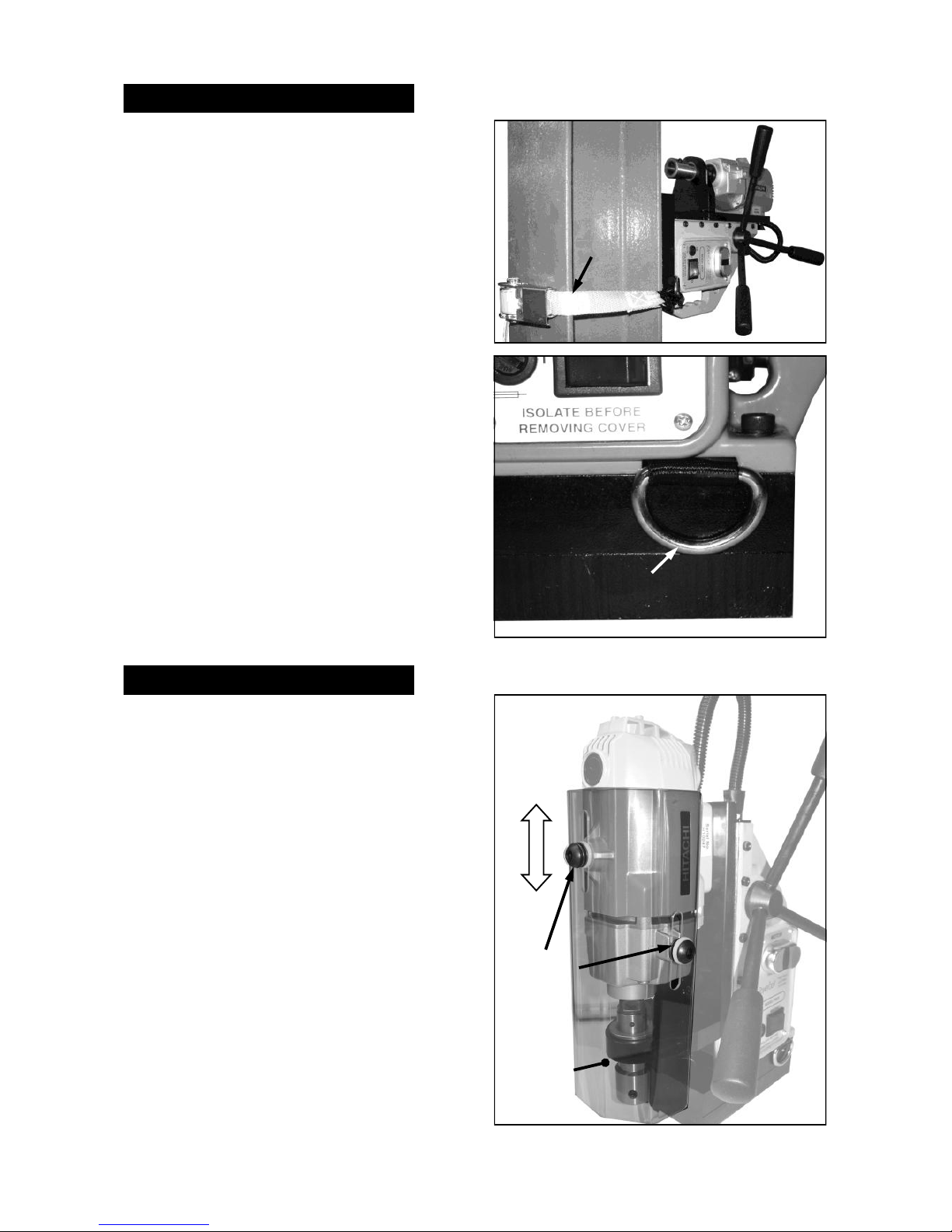
USING THE SAFETY STRAP carry
A ratchet type safety strap is provided.
The power tool has 2 x „D‟ loop rings to allow
the hooks on the safety strap to be attached
securely.
Always ensure the strap is correctly fitted and
the machine is secure BEFORE starting the
motor unit.
The safety strap is used to reduce the risk of
injury in the case of a power supply or
electrical malfunction.
The strap will hold the power tool if the
electro-magnet looses its magnetic adhesion.
If the strap becomes damaged or lost, it must
be replaced BEFORE using the power tool.
DO NOT use the safety strap as an
alternative clamping method, the
electro-magnet should have good magnetic
adhesion at all times whilst using this power
tool.
‘D’LOOP
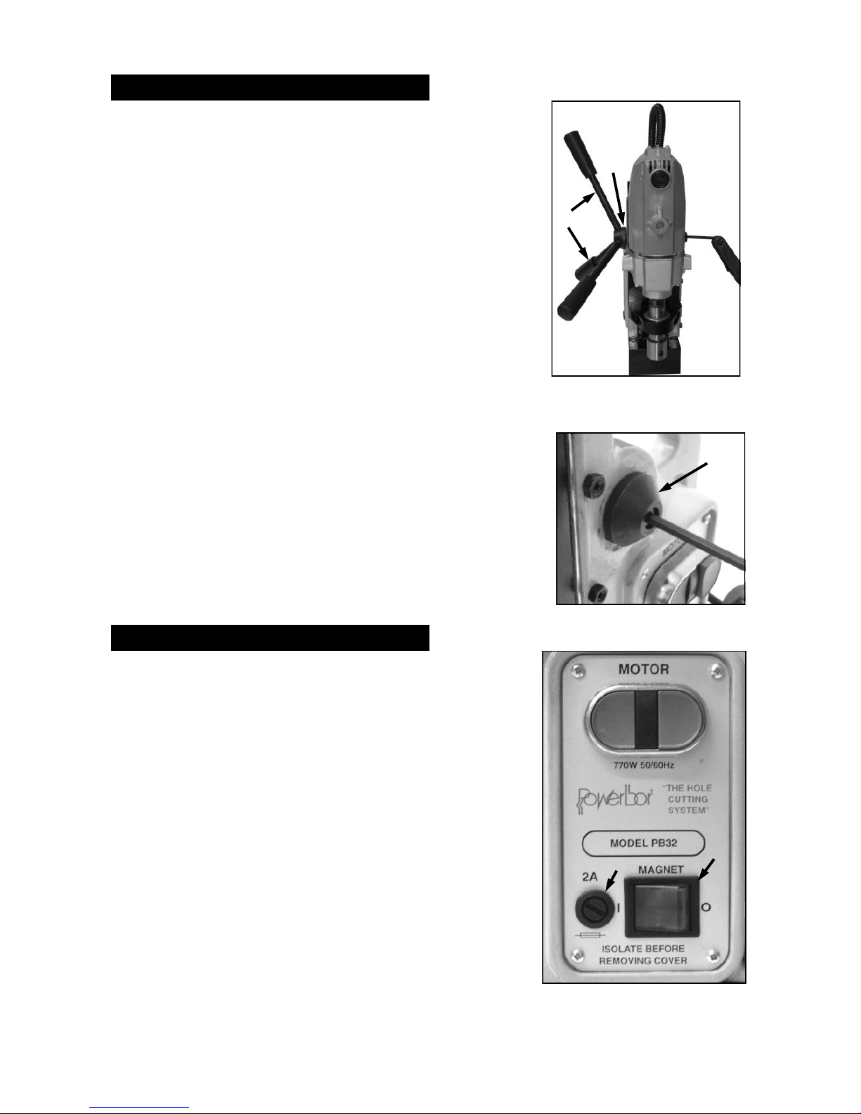
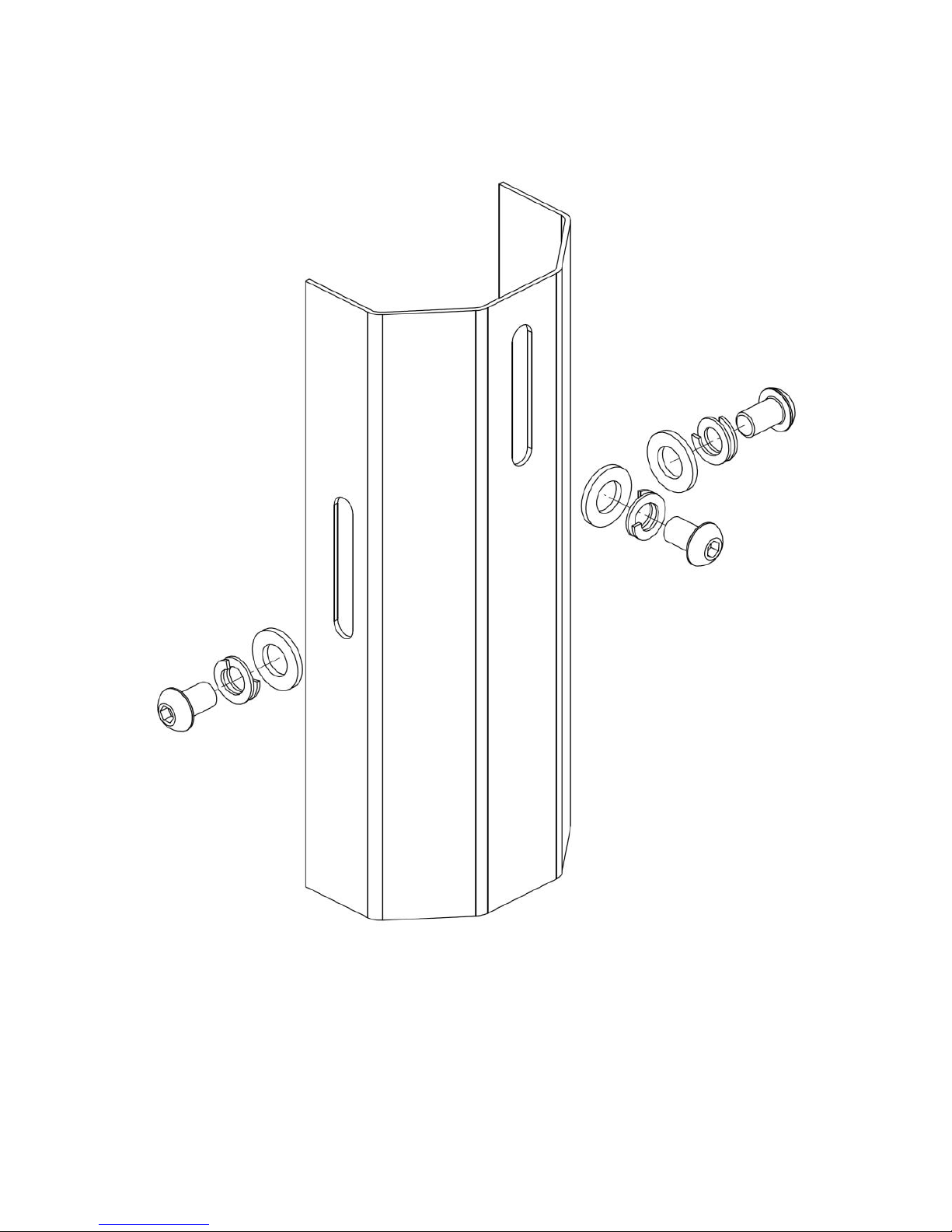
USING THE SAFETY GUARD
FIXING
SCREWS
SAFTEY
GUARD
RATCHET
STRAP
A safety guard is supplied with this power
tool, it should be attached BEFORE using the
power tool.
The guard is attached at 3 points, by button
head screws to the motor. The nylon washer
should be closest to the guard with the spring
washer between the nylon washer and the
screw head.
The screws should be tightened just enough
to allow the spring washers to hold the guard
up.
The guard has approximately 50mm of travel
which is adequate standard length cutters.
The guard should be adjusted so it is able to
slide with light pressure.

11 PB32 - Revised 120810
MOUNTING CUTTERS INTO THE ARBOR
The holder for the cutting tool is known as the
arbor. The arbor is designed to accept
Powerbor 3/4” Weldon shank annular cutters.
The Powerbor annular cutters normally have
two flats disposed at 90°to each other.
To mount the cutter.
First ensure the ejector pin is in place.
Align the two flats with the two fixing screws.
Push the cutter up into the arbor until it stops.
Tighten the two fixing screws onto the cutter
flats with the hex keys supplied.
FITTING THE DRILL CHUCK SUPPLIED
To replace the arbor (A) with the drill chuck
supplied first remove the arbor.
To do this, using the spanners supplied, place
one spanner on the flats of the drill output
shaft.
Turn clockwise (as viewed from above) until
the spanner meets the dovetail slide.
Place the the second spanner on the flats of
the arbor, apply pressure, again clockwise as
viewed from above.
If possible the magnet can be used to hold
the machine whilst removing the arbor.
If the arbor is tight the spanner on the arbor
flats can be tapped with a soft mallet.
Once the arbor is unscrewed the arbor
support bracket (B) needs to be removed.
This is accomplished by removing the two
hexagon socket head cap screws.
To fit the drill chuck simply screw it into place
on the spindle nose.
A special left handed screw is provided to
hold the chuck if the spindle rotation is
reversed (PB32 Combi only)
Replacement of the arbor is a reversal of the
procedure above.
TO REMOVE ARBOR
A
B
12 PB32 - Revised 120810
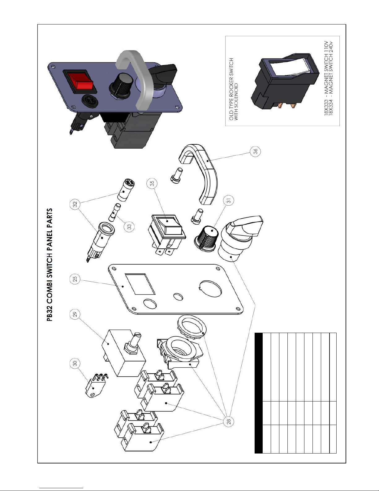
REVERSING OF THE HANDLES
The three handles (C) which raise and lower the drill unit
are attached to the pinion shaft (D).
These handles and the pinion shaft itself can be turned
around so the handles can be used on each side of the
machine. This is useful if access is limited on one side of
the machine because of the machines location.
The handles are normally mounted on the same side as the
controls, if they need to be reversed the following procedure
should be used.
First, the drill unit and its slide should either be supported or
put into its lowest position to prevent the risk of it falling
when the pinion is disengaged.
The hexagon head cap screw in the end of the pinion shaft
end cap (E) should be unscrewed.
The pinion shaft end cap can then be removed, the pinion
shaft and handle assembly can be withdrawn.
The pinion shaft and handle assembly can then be mounted
on the opposite side of the machine, taking care to ensure
the pinion gear teeth engage with the rack teeth.
The pinion shaft end cap and its hexagon head cap screw
should then be replaced and re-tightened.
C
D
E
MAGNET CONTROL PB32
The magnet is controlled by the magnet switch (F) located
at the bottom of the control panel.
„O‟ indicates magnet OFF „I‟ indicates magnet ON.
Ensure the magnet switch is OFF before connecting the
power supply.
Ensure the magnet is clean and free from debris and that
the machine is on a flat clean ferrous surface of the
required minimum thickness (10mm).
To switch the magnet ON, press the switch to the „I‟
position, the switch will illuminate to indicate there is a
power supply to the machine.
The security of the magnet should always be physically
checked BEFORE starting the drill unit.
The magnet is protected by a 2A fuse (G).
F
G

13 PB32 - Revised 120810
MOTOR CONTROL PB32
H
The drill unit or “motor” of the PB32 is controlled by a twin
push button switch at the top of the control panel.
The green button is ON the red button is OFF.
The green button is flush with the surrounding bezel.
The red button is raised above the surrounding bezel.
This is to prevent inadvertent operation of the drill unit.
The motor will not operate unless the magnet is switched
ON first.
BEFORE staring the motor the security of the magnet
should be physically checked, if any movement is possible
this should be rectified BEFORE using the drill.
If motor control has an under-voltage relay, if the power is
interrupted the motor will stop and will not restart when the
power is resumed until the motor control is operated again.
The PB32 is a single speed drill unit with a nominal no-load speed of 550 rev/min.
The PB32 Combi is variable speed, but for the purposes of using annular cutters on mild
steel, the speed should be st to its maximum.
Under load the drill unit will regulate its speed depending on the load applied.
ie: a small cutter will run faster than a larger cutter (if the same feed rate is applied)
The PB32 has the optimum power / torque / spindle speed for HSS annular cutters in the
range Ø12mm to Ø 32mm, cutting EN10025 S235J steel or its equivalent.
CUTTING SPEEDS—HSS CUTTERS
Cutting Speeds (Imperial)
Aluminium 2.37”
Brass 1.75”
Mild Steel 1.00”
High Tensile 0.37”
0.37” 0.75” 1.25” 1.62” 2.0” 2.37” 2.75” 3.12”
Cutter Diameter (inches)
Material
Surface Speed
(Inches/min)
Cutting Speeds (Metric)
Aluminium 60
Brass 45
Mild Steel 24
High Tensile 9
Material
Surface
Speed
(M/min)
PLEASE NOTE: These figures are quoted for guidance, actual performance will be
dictated by material type, thickness, hardness, application and cutter condition
Cutting Speeds—suggested speed rates for varying cutter diameters / materials

14 PB32 - Revised 120810
MAGNET CONTROL PB32 COMBI
The PB32 Combi Magnet Control switch (I) is positioned at
the top of the PB32 Combi control panel.
„O‟ indicates magnet OFF „I‟ indicates magnet ON.
Ensure the magnet switch is OFF and the FWD/REV
switch is in the OFF position before connecting the power
supply.
Ensure the magnet is clean and free from debris and that
the machine is on a flat clean ferrous surface of the
required minimum thickness (10mm).
To switch the magnet ON, press the switch to the „I‟
position.
The security of the magnet should always be physically
checked BEFORE starting the drill unit.
I
J
K
K
OFF
FWD
REV
MOTOR CONTROL PB32 COMBI FWD/REV
The PB32 Combi drill unit or “motor” is controlled by a three position rotary switch (K) at
the bottom of the PB32 Combi control panel.
The motor or FWD / OFF / REV switch should be in the OFF position before connecting
the power supply to the machine.
The magnet switch should be in the ON position and the security of the magnet should
always be physically checked BEFORE the spindle is started.
To start the spindle in its normal rotation the three position selector switch should be in
the FWD position.
To start the spindle in the opposite rotation the three position selector switch should be in
the REV position.
The FWD / OFF / REV switch should NEVER be switched from FWD to REV or REV to
FWD without waiting until the motor has stopped rotating. Failure to follow this instruction
will result in damage to either the motor or switchgear.
The motor speed control on the PB32 Combi is intended mainly for tapping operations.
For normal use with an annular cutter the speed should be set to maximum to allow
maximum power.
The motor speed control knob (K) allows speed to be reduced by turning counter
clockwise and increased by turning clockwise.
Reducing the speed significantly will reduce the power/torque available.
MOTOR SPEED CONTROL PB32 COMBI

15 PB32 - Revised 120810
USING THE DRILL WITH ANNULAR CUTTERS
Insert the correct pilot pin for the cutter into the pilot pin hole through the shank of the
cutter.
Mount the cutter in the tool holder (arbor) of the machine as described in previous
chapters, ensuring the cutter is secure and correctly fitted.
Position the machine on the work piece ensuring the magnet is on a flat clean ferrous
surface and the work piece is not below the minimum recommended thickness.
Use the pilot pin to align the centre of the cutter to the desired hole position.
Switch on the magnet and physically check the machine is securely adhered to the work
piece.
Once in position, attach the safety strap, if the magnetic adhesion fails for some reason
the safety strap will reduce movement of the machine.
Apply cutting fluid through the small holes in the arbor, the arbor has a small reservoir for
coolant which is fed down through the central pin hole to the cutter. The use of cutting
fluid will enhance the quality of the cut and prolong the life of the cutter.
Lower the safety guard provided.
Switch on the drill motor, feed the cutter down by using the three handles provided.
Proceed with caution, apply pressure gradually until the cutter has formed a groove of
approx 3mm (1/8”). Once a groove is established the pressure can be increased.
DO NOT apply excessive pressure, if excessive pressure is required it is a sign the cutter
may be worn, continuing to use a worn or blunt cutter will result in damage to the drill
motor.
If the drill motor slows significantly under load ease off the downward pressure.
On deep holes it may be necessary to withdraw the cutter to remove swarf and to apply
more cutting fluid.
A cutter in good condition will need only moderate feed pressure and will produce
continuous chips or swarf. Broken chips or swarf indicate a cutter or material problem, so
care should be taken.
If excessive swarf builds up during the cut it may be necessary to withdraw the cutter to
remove the swarf, care should be taken as the swarf will be both hot and sharp.
As the cutter begins to break through the feed pressure should be reduced slightly.
When the cutter breaks through a slug of material at the centre of the cut will be ejected.
This will be both hot and sharp. Care should be taken when handling the slug.
Care should be taken that the ejection slug is safe and can not injure anyone in the
vicinity, the slug should be prevented from falling where possible.

16 PB32 - Revised 120810
TAPPING — PB32 COMBI ONLY
The PB32 Combi, in addition to drilling with annular cutters, is designed to allow the
tapping of screw threads.
The tapping capacity of the PB32 Combi is M6 to M12.
This machine has variable speed and both forward and reverse spindle rotation.
Magnetic based drills are normally used for cutting through holes with annular cutters,
the tapping facility of this drill is for tapping through holes.
If tapping of blind holes is required then an automatic reversing tapping chuck should be
used for best results.
The images below show the available Powerbor taps and holders, these have Powerbor
weldon shanks and fit directly into the 3/4” Weldon shank arbor of the machine.
COMBI DRILL/TAP - M6 - M10
(M12 With Annular Drill)
2-IN-1 DRILL TAP - M12
To tap a hole first set up the machine as for drilling with annular cutters in previous
chapters. Ensure the machine is secure before commencing any drilling operation.
Combi Drill/Tap
Drill the hole to the recommended tapping size for the thread to be cut.
Without disengaging the magnet replace the drill with the tap.
Set the spindle speed to the required tapping speed, apply tapping or cutting compound.
Start the drill spindle in the forward direction and feed the tap into the hole until it begins
to cut. Once cutting the tap will feed itself through, only gentle pressure on the feed
handles should be necessary.
Once the tap has threaded through the plate the drill should be stopped immediately.
The drill spindle should then be switched to reverse and the tap can be fed back out of
the hole.

17 PB32 - Revised 120810
TAPPING — PB32 COMBI ONLY (Cont.)
2 - IN - 1 Drill Tap
When using a 2 - IN - 1 Drill Tap, this type of tap is restricted to plate thicknesses of the
diameter of the tapping size. ie: M12 = 12mm plate. This is due to the length of the plain
portion of the shank after the threaded portion.
If the plate to be drilled is thicker than the diameter of the thread to be cut, the Combi
type drill and tap should be used.
Position the drill and ensure the security of the magnet on the work piece.
Set the spindle speed to the required speed, drill the hole with the drill portion of the
cutter, it may be necessary to slow the speed (depending on size) before tapping.
Always use tapping compound or cutting paste for best results and prolonged cutter life.
Allow the tap the feed through with little or no feed pressure, once the threaded section of
the tap is through the drill will stop feeding and just rotate.
Stop the spindle, switch to reverse, help the tap to begin feed up with very light upward
pressure on the feed handles.
Once the tap is out of the hole the machine can be removed.
IMPORTANT when tapping NEVER switch the machine from forward to reverse without
allowing the motor to stop first. Switching directly from foward to reverse can damage the
motor and switchgear.
TAPPING SPEEDS rev/min
Tap Size Mild Steel Alloy Steel
M6 480 320
M8 360 240
M10 290 190
M12 240 160
The tapping speeds shown above are for guidance only, condition of the cutter and
specific material conditions will dictate actual speeds required.
OPTIONAL COOLANT SYSTEM
The arbor supplied with PB32 and PB32 Combi has an internal reservoir for coolant built
in.
If additional coolant capacity is required, an external coolant system which feeds through
the arbor is available.
This system must be specified at time of purchase, as the external coolant system can
not be retro fitted to existing machines.

18 PB32 - Revised 120810
MAINTENANCE
To keep this machine in a safe working condition regular certain maintenance is
required.
1. The gib strip on the dovetail slide must be adjusted to eliminate any free play.
2. The dovetail slides will need to be lubricated will oil periodically.
3. The magnetic base should be inspected for damage on its magnetic surface or for
any damage to the resin, any damage should be repaired before using the drill.
4. A monthly inspection of the carbon brushes is recommended, excessive wear could
lead to motor damage or malfunction.
REPLACING CARBON BRUSHES
The carbon brushes (M) can be removed by
simply unscrewing the brush cap (L).
The brush has a spring and metal cap
attached, simply withdraw the brush to
inspect or replace it.
When replacing the brush, slide it into the
brush holder, make sure the metal cap of
the brush seats in the recess on the brush
cap, then screw the brush cap home.
Always use genuine replacement parts.
The brushes on this drill unit have an auto
stop feature, when the brush reaches its
wear limit to motor will stop until the brushes
are replaced
L
M
ACCESSORIES
18Y170—PB32
CHUCK ADAPTOR
This allows the drill
chuck to be quickly
placed into the arbor
of the machine.
18YPIPE—PIPE CLAMP
This allows the drill to be mounted
on a pipe or cylindrical object, the
magnet attaches to the “saddle” so
the material of the workpiece does
not need to be magnetic.

19 PB32 - Revised 120810
PB32 WIRING DIAGRAMS

20 PB32 - Revised 120810
PB32 COMBI WIRING DIAGRAMS

21 PB32 - Revised 120810
PB32 STAND - PARTS DIAGRAM
ITEM Part No. Description
1 18Y138 MAIN BODY CASTING
2 18Y134 ELECTRO-MAGNET BASE
3 18X312 BRASS GUIDES (PAIR)
4 18Y140 MACHINE RACK
5 18X304 DOVETAIL SLIDE
6 18Y141 ARBOR SUPPORT BRACKET
7 18Y130 ARBOR ASSEMBLY (1/2" X 20 UN)
8 18X321 ARBOR SPRING
9 18X323 ARBOR PISTON
10 18X206 INTERNAL CIRCLIP
11 18X309 SPINDLE BUSH
12 18Y143 SAFETY GUARD
13 18X311 RETAINING BRACKET
14 18X524 PINION END CAP
15 18X502 PINION BUSH
16 18Y144 PINION SHAFT
17 18X314 HANDLE (12mm)
18 18X520 KNOB (12mm)
17+18 18Y145 HANDLE/KNOB COMPLETE
ITEM Part No. Description
19 18Y519 CABLE GLAND (CORD GRIP)
19a 18X519/A CONDUIT GLAND
20 18Y180 CONDUIT LEAD
21 18Y181 MAINS CABLE 110V (2P+E)
22 18X503 MAINS CABLE 230V (UK)
23 18X316/A SIDE PANEL
24 18X515 RECTIFIER UNIT
25 18X315/A CONTROL PANEL
26 18Y182 START/STOP SWITCH
27 18X513 POWER RELAY 110V
28 18X514 POWER RELAY 230V
30 18X510 MAGNET SWITCH (110V & 230V)
31 18X511 FUSE HOLDER
32 18X512 2A FUSE
33 18X224 M5 X 18 CONE POINT SCREW
34 18X205 M8 X 8 GRUB SCREW
35 18X330 PLASTIC CASE
36 18Y170 CHUCK ADAPTOR
37 18Y136 ELECTRICAL PANEL ASSEMBLY
28
22
22 PB32 - Revised 120810
ITEM Part No. Description
25 18X315/F PB32 COMBI SWITCH PANEL
28 18Y183 MOTOR DIRECTION SWITCH
29 18X801 SPEED CONTROL MODULE
30 18X806 TRIAC
31 18X802 SPEED CONTROL KNOB
32 18X511 FUSE HOLDER
33 18X512 2A FUSE
35 18X510 MAGNET SWITCH
36 - HANDLE
23 PB32 - Revised 120810
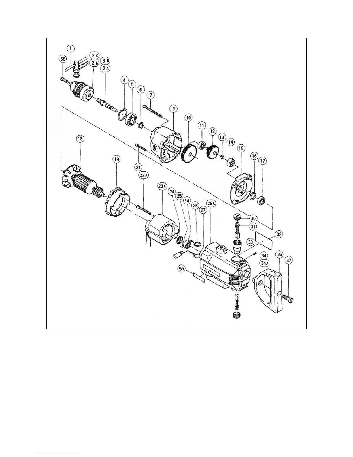
PB32 MOTOR - PARTS DIAGRAM

24 PB32 - Revised 120810
PB32 MOTOR - PARTS LIST
Item Part Number Description
Item Part Number Description
1
18ZA01 CHUCK WRENCH - HITACHI 930-515
30
18ZA30 BRUSH CAP - HITACHI 961-781
2b
18ZA02B DRILL CHUCK (13 VLR)(SUPPLY WITH 18ZA01) - HITACHI 950-275
31
18ZA31 SET CARBON BRUSHES - HITACHI 999-073
3b
18ZA03B SPINDLE D13 - HITACHI 981-667
33
18ZA33 BRUSH HOLDER - HITACHI 981-586
4
18ZA04 RETAINING RING (10) - HITACHI 939-556
34a
18ZA34A HEX SOCKET SET SCREW - HITACHI 985-114
5
18ZA05 BALL BEARING - HITACHI 620-2VV
36
18ZA36 D-TYPE HANDLE - HITACHI 982-794Z
6
18ZA06 RETAINING RING (10) - HITACHI 939-544
37
18ZA37 M10 SPECIAL BOLT - HITACHI 983-796Z
7
18ZA07 TAPPING SCREW - HITACHI 957-725
38
18ZA38 TAPPING SCREW - HITACHI 937-807
8
18ZA08 M5 SPRING WASHER (10) - HITACHI 949-454
39
18ZA39 M5 WASHER (10) - HITACHI 949-424
9
18ZA09 GEAR COVER - HITACHI 981-650
40
18ZA40 HANDLE (B) - HITACHI 984-361
10
18ZA10 FINAL GEAR - HITACHI 983-448
41
18ZA31 SET CARBON BRUSHES - HITACHI 999-073
11
18ZA11 BALL BEARING - HITACHI 627-VVM
42
18ZA42 SWITCH (2P PILLAR) - HITACHI 971-667Z
12
18ZA12 SECOND PINION - HITACHI 981-652Z
43
18ZA43 TUBE (D) - HITACHI 981-373
13
18ZA13 M8 WASHER (10) - HITACHI 949-426
44
18ZA44 PILLAR TERMINAL - HITACHI 982-804Z
14
18ZA14 BALL BEARING - HITACHI 608-VVM
45
18ZA45 PILLER TERMINAL (B) - HITACHI 982-805Z
15
18ZA15 INNER COVER ASSEMBLY - HITACHI 982-791
46
18ZA46 REVERSING SWITCH ASSEMBLY - HITACHI 982-802Z
16
18ZA16 WASHER - HITACHI 984-357
47
18ZA47 HANDLE (A) - HITACHI 984-360
17
18ZA16 WASHER - HITACHI 984-357
48
18ZA48 TAPPING SCREW (W/W) D4 X 20 - HITACHI 982-095
18
18ZA18J ARMATURE - 110V - HITACHI 981-657J
49
18ZA49 SUPPORT (B) - HITACHI 930-153
-
18ZA18 ARMATURE - 240V - HITACHI 981-657
51
18ZA51 TAPPING SCREW - HITACHI 930-446
19
18ZA19 FAN GUIDE - HITACHI 981-562
52
18ZA52 TUBE (D) - HITACHI 981-373
21
18ZA21 TAPPING SCREW - HITACHI 931-875
53
18ZA53 TERMINAL 50061 (10) - HITACHI 959-146
22
18ZA22 TAPPING SCREW - HITACHI 981-561
54
18ZA54 CORD CLIP - HITACHI 960-266
23
18ZA23J FIELD COIL - 110V - HITACHI 982-797J
55
18ZA55 HITACHI LABEL - HITACHI 957-561
-
18ZA23 FIELD COIL - 240V - HITACHI 982-797
56
18ZA56 CORD ARMOUR (D8.8) - HITACHI 953-327
24
18ZA24 WASHER (C) - HITACHI 984-367
57
18ZA57 CORD - HITACHI 500-231Z
25
18ZA25 BEARING LOCK - HITACHI 946-362
58
18ZA58 SPECIAL SCREW - HITACHI 981-122
26
18ZA26 BRUSH TERMINAL - HITACHI N/A
27
18ZA27 BRUSH TERMINAL - HITACHI 982-801Z
18X305 COMPLETE HITACHI D13 MOTOR UNIT - 110V
28a
18ZA28A HOUSING ASSEMBLY - HITACHI 982-790Z
18X306 COMPLETE HITACHI D13 MOTOR UNIT - 240V
29
18ZA29 SIDE HANDLE FOR M10 - HITACHI 981-205

25 PB32 - Revised 120810
ITEM Part No. Description
7 18Y130 ARBOR BODY (1/2" X 20 UN)
8 18X321 ARBOR SPRING
9 18X323 ARBOR PISTON
10 18X206 3/4" INTERNAL CIRCLIP
34 18X205 M8 x 8 SOCKET SCREW
PB32 ARBOR
26 PB32 - Revised 120810
PB32 SAFETY GUARD
 Loading...