

Page 1
An inconspicuous reliable 35m external passive infrared detector
that works in conjunction with the GJD security lighting controllers.
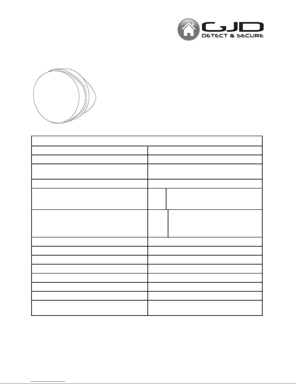
The Opal XL is encased in a robust high impact ABS housing. The
plug electronics module is supported by an internal bracket which is
fully adjustable horizontally and vertically. Further protection against
harsh environments is offered by a separate polythene lens cover
which conceals the angle of detection from any intruder and totally
hides the wiring.
-1-
Installation Manual
OPAL XL SPECIFICATIONS
Area 10 to 35m (adjustable) up to 750 sq m
Coverage 90º 35m x 30m max
Adjustment 180º pan + 90º tilt
Area reduction mask (if required)
Lens Fresnel: 36 zone - White light lter
No. 1 Output ‘A’ Open collector -ve switching - 25mA
max.
Alarm period 400ms
No. 2 Output ‘S’ Open collector -ve switching - 25mA
max
Alarm period : detection +60 seconds
Adjustable: Dusk (2 Lux) to 24 hour
Power Input 9 to 15VDC
Current 6mA (12V nominal)
Control Digital ASIC/microprocessor
Operating Temp -20º to +55º C
Protection Rating IP55 - High Impact ABS Housing
Dimension 104 x 104 x 94mm Weight 136 grams
Mounting Height - Variable - optimum height 3 metres
Cable up to 200m: standard 4 core 7/0.2mm
up to 500m: 8 core 16/0.2mm use double core
Opal XL
GJD 020 Opal XL 35m External PIR
Page 2
INSTALLATION
Ensure the unit is mounted on a vertical surface. The
multifunction lens shown on page 3 produces 9 long and
9 short range beam patterns, When positioning the unit
remember that movement across the beams produces
the best response whiles movement directly towards the
detector will be less responsive.
During installation the electronics must be protected
against water, as trapped moisture can effect or damage
the unit.
1. First remove the polythene cover by pulling forwards,
then remove the lens module by pulling it out of the
forked bracket.
2. Drill the wall to accept the top xing and the lower
cable entry, The holes should be on 16mm centres.
3. Feed standard 4 core alarm cable into lower cable
entry; bare the wires and connect to the removable
terminal block.
4. Always ensure when replacing the module that it is
the correct way up for the correct alignment of the beam
pattern. (page 3 multi beam lens data)
5. Replace the front cover with the ventilation hole at
the bottom. Ensure the cover engages both sides of the
outer casing before pressing rmly to locate it securely.
6. Apply the power - the red led ashes for 0.5 second.
-2-
At this stage the unit can be walk tested with
the front cover tted. Adjust the range as
necessary and pan and tilt the lens module
over the eld of view to obtain the correct beam
coverage and ensuring that the detection beams
do not exceed the area being covered.
TESTING THE OUTPUTS
(Alignment of the detection beams)
The range of the detectors increases without the
front cover. Therefore the cover must be tted
during ‘walk test’.
Floodlights should be positioned at the
side or above the detector 60cm (2 feet) is
recommended, provided that the detector is not
in the direct radiated head from the oodlight.
The unit detects the changes in the heat and
movement in the beam pattern area, therefore
trees, shrubs, pounds,boiler ues and animals
should be considered when positioning the
detector. In poor environment utilise the ‘pulse
count’ option on the GJD lighting controllers.
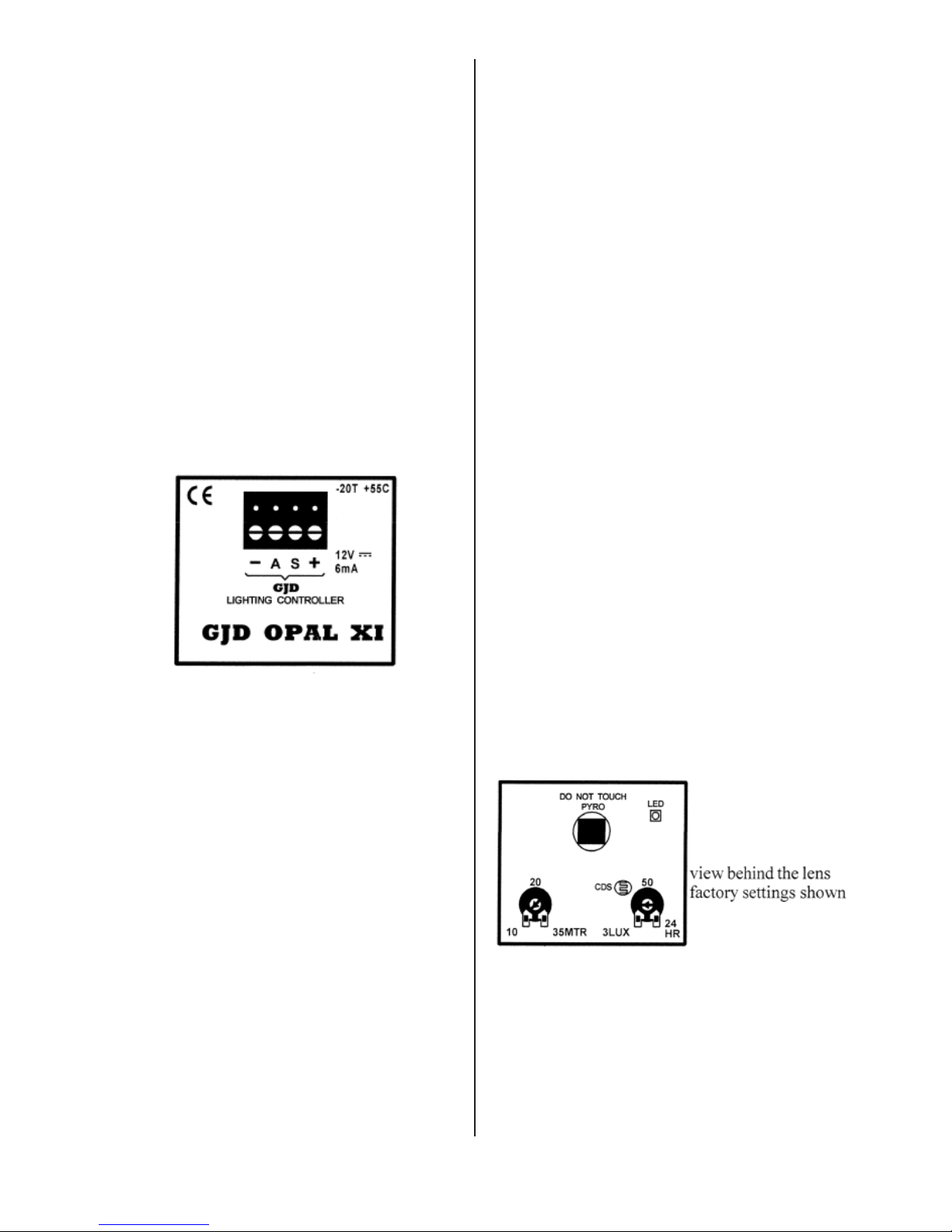
LIGHT LEVEL:
The unit is set at ‘5’ lux. This is the light level that
the ‘S’ -ve output operates when detection takes
place. This is generally considered the average
light level at dusk. If the lux level dial is turned
to 24 hour - this would activate the ‘S’ output for
one minute after last detection irrespective of
light level.
Increase the lux level if the ambient light lvels at
night are higher than 5 lux.
Page 3

MULTIBEAM LENS DATA
The GJD multifunction lens tted to the GJD Opal XL detector produces 9 long range beams and 9 medium to short
range curtain beams. Movement across the beams produces the best response and range, whilst movement towards
the detector will be less responsive.
When mounting higher than boundary fences rotate the module and mask off any beams, either vertically or
horizontally, that fall outside the area being covered. Use portions of the self adhesive silver mask supplied to the
rear, smooth side, of the lens and always replace the correct way up as shown to obtain the exact beam pattern
coverage.
-3-
Page 4

-4-
ADDITIONAL APPLICATIONS
Energising a relay with detection day or night
providing volt free contacts, Suggested relay
12VDC 470 ohms minimum coil resistance.
Energising a relay with detection at night for one
minute longer than last detection.
Driving a low power piezo sounder directly from
Opal XL.
The piezp will sound briey every time a
detection takes place day or night.
Example relays:
RS part number: 376-500
Farnell part number: 176-324
Example piezo:
RS part numver: 245-001
Pin View
Coil Polarity
12 VDC @ 3mA 80db (A) at one metre
Page 5

ENGINEER NOTES
Technical: 01706 363990
Sales: 01706 363998
Fax: 01706 363991
Email: info@gjd.co.uk
Unit 2, Birch Business Park, Whittle,Lane,Heywood,OL10 2SX
 Loading...