

Page 1

GJD OPAL RFX WIRELESS 35 METRE EXTERNAL PIR
I
NSTALLATION MANUAL
- 1 -
THE WIRELESS OPAL RFX EXTERNAL PASSIVE INFRARED INTRUDER
DETECTOR
DESIGNED TO DETECT AND TRANSMIT RELIABLE EVENT
BASED
TRIGGERS TO THE WEATHERPROOF RFX-3 RECEIVER. THESE
COMBINED
UNITS ENABLE THE SIMULTANEOUS OR INDIVIDUAL
CONTROL
OF CAMERAS, VCR'S, DVR'S AND VIRTUALLY ALL LOW-
VOLTAGE SWITCHING REQUIREMENTS.
THE WEATHERPROOF RECEIVER WITH FRONT AND REAR TAMPER OUTPUT CAN BE POSITIONED IN LINE OF
SIGHT
UP TO 150 METRES AW AY. THE ACTIVE STAT E OF UPTO 3 OPAL RFX PIR'S IS CONST ANTLY
MONITORED
. THESE SIGNALS ARE DIRECTED TO THEIR RESPECTIVE VOLT FREE OUTPUTS AND IN ADDITION
THERE
ARE A FURTHER EIGHT INDIVIDUAL MONITORING AND INFORMATION OUTPUTS.
OPAL RFX WIRELESS P.I.R (GJD018)
Supply:
2 x AAA Alkaline 1.5 volt (not supplied)
Low power typical battery life two years.
Transmission - 150 metres line-of-sight:
433.92 MHz frequency - SAW stabalised
Coverage Range 10 to 35 metres:
35 x 30 mtrs max.with 90º multifunction lens
Internal adjustment 180º pan + 90º tilt.
Mounting Heights: (variable)
3 metres high for multi-beam coverage
6 metres high for curtain covage and
1.5 metres for pet immunity (mask supplied)
Processing - Non-volatile memory:
Intelligent signal processing:
Digital & intergral white light filter
16 million possible identification codes
Adjustments:
Detection signal (CCTV) timer 0.4 to 60 secs.
Light level signal 2 lux to daylight
Pulse count 1 (2 & 3
<
6 seconds)
Temperature: -20 C + 55 C
Detector Housing:
ABS high impact IP55 rated
W eight - 152 grams
Dimensions 110high x 100wide x 100 deep
RFX-3 RECEIVER (GJD017)
Supply: 12VDC @ 35mA nominal
(9 to 20VDC maximum)
Outputs (CCTV):
3 x independent channel outputs (24hr)
Selectable N/O (form A) or N/C (form B)
Individual timers 0.4 to 60 seconds after last
detection. Non volatile memory
Outputs (A):
3 x independent switching -ve outputs (24hr)
rated @ 250mA - 0.4 second on detection.
RF loss of signal outputs:
3 x RF/signal - ve switching rated @ 250mA
Lux Output (S):
1 x photocell controlled -ve switching
Active 60 seconds after last detection
Tamper:
Back & Front tamper volt free output (form B)
Indication with outputs:
Independent channel active & low battery
Temperature: -20 C + 55C
Weatherproof Enclosure:
IP65 high impact ABS
W eight - 340 grams
183 high x 123 wide x 60mm deep
Page 2
- 2 -
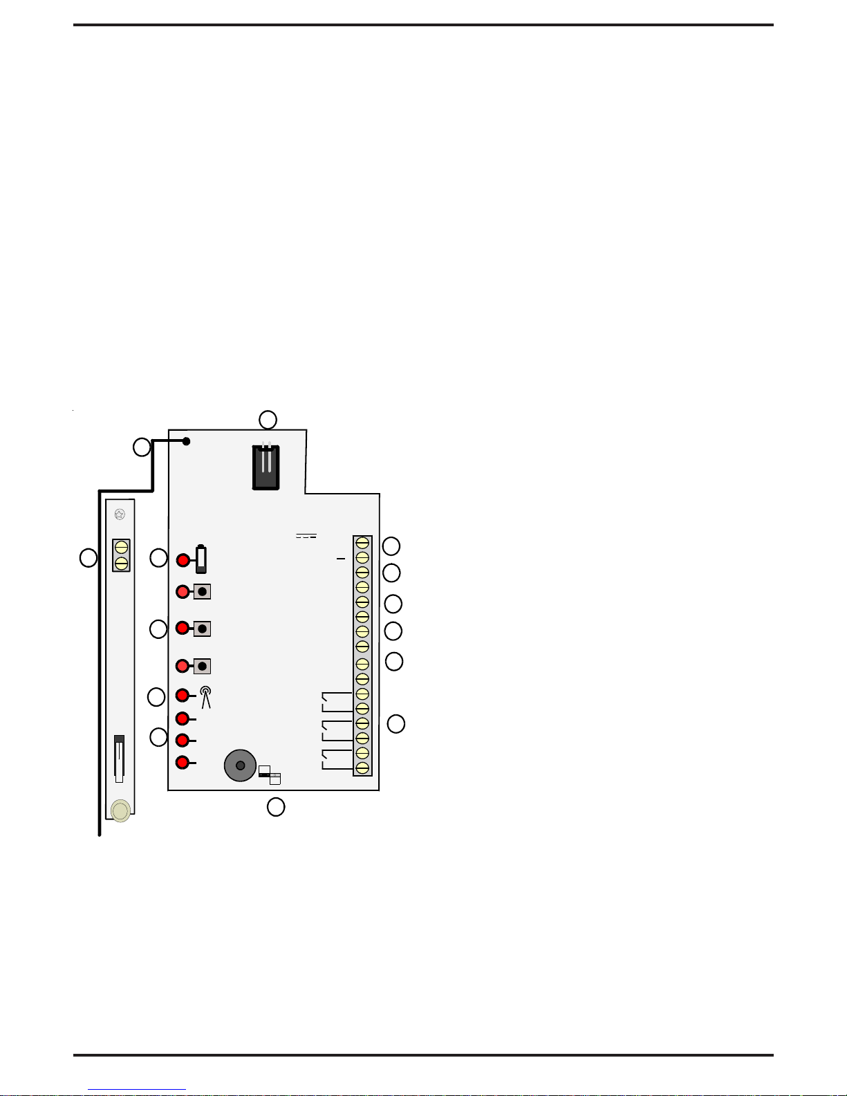
1 X
FEA TURES:
1) Secure wire code transfer connector
2) Power Supply input
3) LO - output pulses every 5 seconds
when any batteries are low
4) 3 x 'A' - ve outputs which activate for
0.4 second on detection (24 hour)
5) 'S' output - photocell controlled
6) 3 x RF -loss of active signal outputs.
Activates 5 mins. after not receiving
a signal from a registered detector .
7) 3 x independent volt free CCTV
contacts. Adjustable 0.4 to 60 seconds.
8) Selection jumper - Normally open or
normally closed CCTV contacts.
9) 3 x RF loss of signal LED indicators
10) Reception - gives indication of the
radio signal being received.
(a) Flicker = normal
(b) On and off indicates conflict with
other radio equipment on the same
frequency in close proximity.
11) 3 x Channel buttons
For use in code transfer function only .
Plus detection indicators that light for
the length of the CCTV timer setting
12) Battery low indicator corresponding
detection indicator will also flash every
5 seconds when battery is low (see 3)
13) Tamper will activate/
(a) when cover removed or
(b) displacing from the mounting point.
14) Aerial
10
11
14
8
7
6
5
4
3
2
1
9
GJD
LN
1
2
3
RF3
RF2
RF1
RFX-3
RECEIVER
CCTV 1 2 3
N/C
N/O
T-20+55C
12V
35mA
N/C
TAMPER
CCTV
3
CCTV
2
CCTV
1
LO
A1
A2
A3
S
RF1
RF2
RF3
+
1213
The RFX-3 Receiver monitors the active
state of up to three Opal RFX passive infra
red detectors.
The RFX-3 Receiver can be mounted
externally or internally. The transmission
distance of 150 metres can be obtained if the
detectors are in true line of sight to the
receiver. When installing the RFX-3
Receiver internally, the transmission distance
of 150 metres will be reduced depending on
the thickness and type of material structure
the radio signals have to pass through or
around.
It is advisable to conduct an RF continuity
test when mounting the receiver internally to
ensure that the radio signals can be received
in the desired location. (RF continuity test
page 5)
been transferred via the secure wire code
learning link. This transfer is only required
on the initial setup, any subsequent changes
to the detector programming will be relayed
by radio automatically to the receiver.
(programming chart - page 5)
Wireless transmission.
Each detector transmits radio signals to the
receiver and has over 16.7 million individual codes. The receiver only responds to
the transmitter that has been linked to a
channel to identify it.
The receiver can only analyse this
information after the individual code has
(fig1)
Page 3
- 3-
RFX-3 RECEIVER INSTALLATION
The receiver has five cable inlets which have
individual moisture and insect blanking
plates. There are three double and two single
entry clamps for 6/8 core 5mm OD signal
cables.(see fig 2)
Feed the cable from behind the unit and push
into the cable guides. Ensure that the moisture and insect blanking plates are inserted in
to any unused cable clamps.
1.5 VOLT
1.5 VOLT
PROGRAM
BUTTON
+
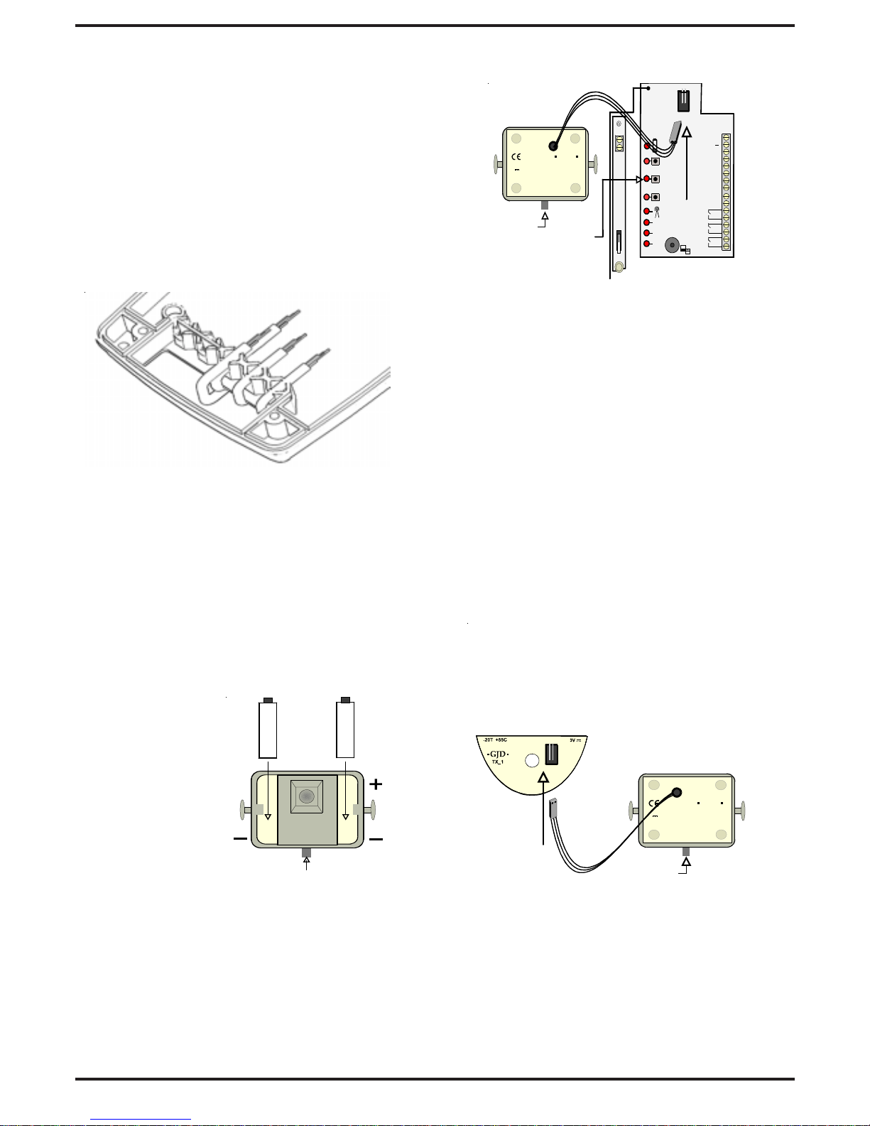
1) Apply the 12VDC to the receiver
2) Plug in the link wire from the first
detector in to the receiver (see fig 4)
3) Press the respective ‘Channel button’
on the receiver once – the LED lights
4) Within 4 seconds press the ‘Program
button’ on the detector once
5) The ‘Channel’ indicator blinks twice.
The code for that detector is stored
and registered to that channel.
6) Remove the link wire from the
receiver and plug into the aerial
transmitter in the back of the
detector . (see fig 5)
Detection signals will be immediately
transmitted to the receiver.
(fig 5)
Repeat Steps 2 to 6 for each detector .
T o check whether a code is stored - press
the channel button once - three beeps
sound.
T o erase a code from the receiver - press
and hold down the channel button until
the continuous beeps end - then release.
PROGRAM
BUTTON
3
V
2XAAA
RFX
-20T +55C
GJD
PROGRAM
BUTTON
3V
2XAAA
RFX
-20T +55C
GJD
LN
1
2
3
RF3
RF2
RF1
CCTV123
N/C
N/O
T-20+55C
N/C
TAMPER
CCT
V
3
CCT
V
2
CCT
V
1
LO
A1
A2
A3
S
RF1
RF2
RF3
+
PROGRAM
BUTTONS
Setup
To transfer the detector code to the receiver.
BATTERY INSTALLATION
1) Remove the Opal RFX cover
2) Remove the module from the bracket
3) Remove the fresnel lens
4) Insert 2 x AAA batteries into the module
as shown.(fig 3) Put the base of the
battery in first then click the'+' in firmly.
(fig 3)
To replace the batteries – push out from the
holes on the reverse of the module.
(fig 2)
(fig 4)
Page 4

- 4 -
1 X
LUX ‘S’ OUTPUT ONLY:
a) 2 lux to 240 lux. = the approximate
light level at which the ‘S’ output is
activated.
b) 24 HOUR = will operate day and night.
All other outputs operate day and night
irrespective of the ‘S’ output setting.
PULSE COUNT:
The range of the unit will decrease if there is
little difference in temperature between the
moving object and the background.
1 will give a fast response
2 gives better immunity with good
response
3 gives higher immunity to false
activation
Timing 1 (2 & 3
<
6 seconds)
TIME 'CCTV' OUTPUT
This is the time in seconds that the 'CCTV'
volt free output will activate after detection.
For setup purposes the respective channel
indicator will also light for this time. Adjust
the jumper link on the RFX-3 Receiver to
select either normally open in alarm condition
or normally closed contacts.
CUSTOMISING
All factory set parameters can be changed to
suit individual requirements. The highlighted
areas on the programming chart show the
factory settings which suit most applications.
Changes can be easily made either before
installation or on site. Once changes have been
made they are stored in a non-volatile memory.
PROGRAMMING
To amend your existing 'Option' and 'Setting'
1) Press the program button on the detector
once for the number of the required 'Option'
(e.g. range-press twice)
2) W ait 4 seconds until the LED goes out.
3) Within 5 seconds press the button again for
the number of the required 'Setting'
(e.g 20 metres-press three times)
4) The LED blinks twice - the new setting is
saved
To amend any other options/settings repeat
steps '1' to '4'
EXAMPLE - T o set the Range to 20 metres
a) Press twice to select Range
b ) W ait until LED goes off (4 seconds)
c) Press three times for 20 metres
Six = will flashout your selected settings
Seven = will reset to GJD factory default settings
Eight/hold = will start the RF continuity test (see pa ge 5)
Nine/hold = will generate and alternative random code ( see page 5)
AUXILIARY
OPAL RFX DETECTOR PROGRAMMING CHART
652
2
2
2
3
3
3
3
4
4
4
5
5
7 8
86 7
Press
Twice -set Range
Three -set Lux Level
Four -set Pulse Count
Five -set Time 'CC TV'
1
1
1
1
10 15 20 25 35 metres
2 5 15 30 60 120 240 24hr 'S'output
1 2 3 pulse count
0.4 1 2 4 8 25 30 60 seconds
then x
for
then x
for
then x
for
then x
for
OPTIONS
wait for indicator to go out
Page 5

- 5 -
RF CONTINUITY TEST
It is advisable to test the RF signal at the
detector location prior to installation.
To enter the RF continuity test mode - press
the program button on the Opal RFX 'eight'
times. On the eighth press - 'hold' the button
down for 5 seconds until the LED goes out
- the LED indicator will then flash and
transmit one signal per second to the receiver.
The corresponding channel indicator on the
receiver will also flash once per second if
there is a strong RF link established.
This test mode will automatically cancel in
five minutes. Alternatively to cancel the ' RF
continuity test - press and hold the program
button until the LED lights then release.
If it is necessary to conduct a site survey
prior to installation of this equipment it is
advisable to power the RFX-3 Receiver
temporarily with a PP3 (9volt) battery.
Register one detector, then conduct an RF
continuity test as detailed above. As the
signals to the receiver are sent once per
second the optimum position of both the
Opal RFX and the RFX-3 Receiver can be
easily established .
CHANGING THE RANDOM CODE
In the unlikely event of another radio signal
affecting the correct operation of a single
channel. The Opal RFX detector can generate
an alternative random code.
Press the program button on the Opal RFX
nine times. On the ninth press 'hold' the
button down for 5 seconds until the LED
goes out, then release the button
Then erase the code from the RFX-3 Receiver
by holding down that 'channel button' until
the beeps stop, then repeat steps '2' to '6' of
the 'Setup' procedure to register the new
code.
OPAL RFX INSTALLATION:
During installation the electronics must be
protected against water, as trapped moisture
can effect or damage the unit.
1) First remove the front polythene cover by
pulling forwards, then remove the lens
module by pulling it out of the forked
bracket.
2) Drill the wall to accept the fixing screw
supplied with the wall plug.
3) Fit the housing to a secure surface. When the
surface is uneven use the 4mm spacer
supplied toensure that the radio signals
transmitted achieve their optimum distance.
4) Always ensure when replacing the module
that it is the correct way up for the
correct alignment of the beam pattern.
(See page 7 Multibeam lens data)
TESTING THE OUTPUTS
(Alignment of the detection beams)
The range of the detector increases without the front protective cover . Therefore
the front cover must be fitted to establish
the correct beam pattern alignment and
when testing the outputs.
When the 'program' button is pressed
momentarily the red indicator lights and
pulse count '1' is automatically selected. The
unit can then be aligned. The red indicator
will light on the Opal RFX and the respective
Channel indicator will flash every time a
detection takes place. This test mode will
automatically cancel five minutes after last
detection. Alternatively, to cancel this 'walk
test mode' press the program button twice.
Page 6

- 6 -
IMPORTANT:
Ensure the detector is mounted upright on
a vertical surface. If mounting the detector
on a conductive or uneven surface it is
advisable to use the mounting spacer
provided.
This will ensure that the aerial is above the
4mm clearance distance required from the
surface to optimise the transmission range.
MIMIMUM DISTANCE 4MM
ALIGNMENT
Passive infra red movement sensors detect the
temperature changes of moving objects.
Movement across the beams produces the best
response and range whilst movement towards
the detector would be less responsive. Use the
pan and tilt facility to accurately target the
detection zone, and adjust the range of the
detector to cover the required area.
The clear mask supplied with the detector can
be cut and applied vertically or horizontally to
eliminate coverage of a single beam, an entire
long range section or corridor beam for CCTV
applications. When mounting higher than
boundary fences mask off any side beams that
fall outside of the required detection area. Also
ensuring that no obstacles, such as walls or
large trees for example, obstruct the beam
pattern view.
As the unit detects a change in heat in its field
of view , therefore to avoid any false alarms,
direct sunshine, trees, shrubs, ponds, central
heating boiler flues and animals should all be
considered when sighting the detector. The unit
is not recommended for mounting on metal
clad buildings in direct sun as excessive heat
produces haze ripple which can produce false
activation's.
.
Floodlights also emit haze ripple. When
installing floodlights to provide movement
activated lighting, position the floodlights at
the side or above the detector. A minimum of
60cm ( 2 feet ) is recommended, provided the
detector is not in direct radiated heat from the
floodlight.
Once alignment is completed, check that the
vent hole of the front cover is positioned at the
bottom. Also ensure that both sides of the outer
casing are engaged before pressing the cover
firmly to securely locate it.
Page 7

MUL TIBEAM LENS DAT A
The GJD multifunction lens fitted to the OP AL RFX detector produces 9 long range beams
and 9 medium to short range curtain beams. Movement across the beams produces the best
response and range, whilst movement towards the detector will be less responsive.
When mounting higher than boundary fences rotate the module and mask off any beams,
either vertically or horizontally , that fall outside the area being covered. Use the selfadhesive clear mask supplied to the rear, smooth side, of the lens and always replace the
correct way up as shown to obtain the exact beam pattern coverage.
- 7 -
051015
TOP
30 35
3
10 20
0deg
0
LONG RANGE 35 METRE SECTION
6TO20METRESSECTION
MULTIBEAM - OPTIMUM
HEIGHT: 3 METRES
RANGE: MAXIMUM
MODULE TILT: 0 DEGREE
6
10 20 30 35
9deg
0
6TO20METRESSECTION
TOP
MULTIBEAM
HEIGHT: 6 METRES
RANGE: MAXIMUM
MODULE TILT: 9 DEGREE
TOP
MASK THIS SECTION OFF
FOR PET ALLEY
APPLICATIONS
UP TO 35 METRES
1.5
10 20 30 35
-2 deg
0
PET IMMUNITY
HEIGHT: 1.5 METRES
RANGE: MAXIMUM
MODULE TILT: -2 DEGREE
5 101520253035
15
10
5
0
5
10
15
Beam Pattern set to maximum
range Masking top section of lens
will reduce range to 20 metres
0 2 4 6 8 101214
6
4
2
0
2
4
6
Beam Pattern set to minimum
range. Masking top section of lens
will reduce range to 6 metres
TOP
MASK TH IS SE CTION OFF
FOR CURTAIN COVERAGE
APPLICATIONS
6
45deg
5
0
CURTAIN COVERAGE
HEIGHT: 6 METRES
RANGE: MAXIMUM
MODULE TILT: 45 DEGREE
Page 8

- 8 -
Installation Notes:
GJD Limited, Bolton, England © 010704
GJD reserve the right to alter the specification without prior notice
Tel: 01204 363998 Fax: 01204 363991 Email: info@gjd.co.uk
 Loading...