

Page 1

-112101
MX25
GJD102 Quad PIR Movement Detector
Package Contents
Package Contains:
●
1 x MX25
●
1 x Allen Key
●
2 x 27mm wall plugs
●
2 x 27mm screws
●
3 x Tamper Feet
●
1 x Tamper Cup
●
1 x Installation manual
Introduction
The MX25 is an attractively styled, 25 metre Passive Infrared (PIR) detector, with advanced features such as dual
tamper switches for case and wall-mount tamper detection,
sensor mounted white-light filter and zone blanking using
vertical curtain shutters and horizontal masking for precise
area coverage.
5. When the detector is aligned, connected, and
programmed to suit the installation, replace the
front cover and lock in place.
The multifunction lens fitted to MX25 produces 5 long range
beams and 5 medium to short range curtain PIR beams
(see Figure 2). The PIR circuitry detects changes in heat
and movement in the beam pattern; therefore items such as
trees, shrubs, ponds, boiler flues, and animals should be
considered when positioning the detector.
Note: The PIR sensor is more sensitive to movement
across the beams, and less sensitive to movement
directly towards or away from the beams.
The detector module is fitted with two sliding shutters to
reduce the detection angle.
When coverage exceeds the desired detection area, adjust
the module as required and mask off any beams, either
vertically or horizontally, to avoid unwanted detection.
Use portions of the self-adhesive silver mask applied to the
rear, smooth side of the lens as shown in Figure 2. Always
replace the lens the correct way up to ensure exact beam
pattern coverage (top of the lens is marked TOP).
When mounted at heights above 3 metres there could be a
significant reduction in the range of detection and the target
will have to move a greater distance within the field of view
before an alarm is generated.
Quick Installation
1. Mount and connect the detector following the
instructions given later in this manual.
2. Configure programming switches as required
referring to instructions given later in this manual.
3. Apply supply voltage to the unit. The blue detection
LED flashes three times.
4. Wait approximately 2 to 3 minutes to allow the
detector to settle.
Note: The front cover must be fitted when walk
testing.
The default settings are:
●
Range: 25 meters
●
Pulse count: 1 (always set to 1 during walk rest)
●
Detection LED: On (recommend for set up process)
Mounting The Unit
Multibeam Alignment & Masking
Configuration Mounting
Height
(Metres)
Tilt (°) Max.
Range
(Metres)
Reference
Multibeam
(Optimum)
3 5 25 Figure 3
Pet Immunity * 1.5 -5 25 Figure
4 & 5
Masking Configurations For Maximum Range
* Black area should be masked for pet alley applications up to 25 meters
(see figure 5).
During installation, protect the electronics against water, as
trapped moisture can affect or damage the unit.
1. Drill the wall to accept the two fixing screws, the
cable entry, and the tamper cup (if used).
Note: We recommend using the tamper cup on
uneven wall surfaces.
2. Remove the cover assembly by loosening the
locking screw using the allen key provided. The
cover hinges from the top and lifts out of the
location slot.
3. Feed the cables into the cable entry and Screw the
unit to the wall ensuring that the tamper pin is
correctly located and that the tamper microswitch is
closed.
Three spare tamper feet of different lengths are
provided to aid installation. The tamper foot is a
push fit and can be removed by carefully pulling it
from the pin.
4. Connect the cables to the screw-terminal block on
the back of the detector PCB (see Figure 1).
Figure 6 shows the pattern for the maximum range in the
optimum position (see Figure 10).
Figures 7 and 8 illustrates alignment recommendations for
when the detector is mounted close to a wall.
The alignment shown in Figure 7 is not recommended. If
the detector module is orientated at an angle of 90° to the
perimeter, the mounting wall may cut off short and medium
range beams. The long range beam will still detect an
intruder, however the wall can cause false alarms when
heated by sunlight.
Figure 8 shows the recommended alignment. The detector
module is orientated at a 55° angle to the perimeter. As a
result, short and medium range beams are parallel to the
perimeter, but the detection range along the perimeter is
reduced.
Page 2
-212101
Programming
Walk Test
Note: It is recommended that the detection LED be
enabled during walk test to aid in set up. The detection
LED lights each time the MX25 detects your presence.
Note: When you conduct a walk test, make sure that the
front cover is in place. Do not conduct walk tests with
the cover removed.
The range of the detector increases without the protective
front cover. Therefore the front cover must be fitted to
establish the correct beam pattern. Use programming chart
to adjust the range as necessary. Pan and tilt the lens
module over the field of view to obtain the correct coverage
area.
Option Switch Configuration Reference
LED ON Switch 1: On (Up) Figure 10
LED OFF Switch 1: Off (Down) Figure 11
Pulse Count 1 Switch 2: Off (Down) Figure 12
Pulse Count 2 Switch 2: On (Up) Figure 13
10 Metre Range Switch 3: Off (Down)
Switch 4: Off (Down)
Figure 14
15 Metre Range Switch 3: Off (Down)
Switch 4: On (Up)
Figure 15
20 Metre Range Switch 3: On (Up)
Switch 4: Off (Down)
Figure 16
25 Metre Range Switch 3: On (Up)
Switch 4: On (Up)
Figure 17
Shaded settings are factory defaults
To change any of the MX25 settings, change the
configuration of the programming switches (see Figure 9)
as required. switch 1 controls detection LED state, switch 2
controls Pulse Count, and switches 3 and 4 control range.
Example: To change the range to 15 metres:
1. Set switch 3 to Off (down position).
2. Set switch 4 to On (up position).
Programming Options Definitions
Pulse Count
This is the number of times the unit has to detect on both of
its sensors before signalling an output.
LED
LED Off – LED disabled.
LED On – LED signals a detection.
Programming Chart
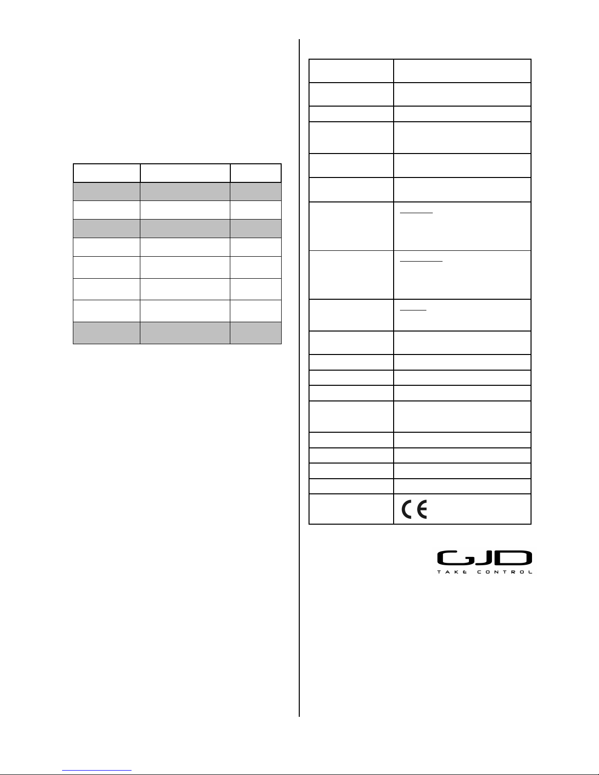
Specifications
Detection Area
Programmable between 10 & 25
metres.
Coverage
90 degrees detection angle, 25m x
25m coverage max.
Adjustment 180 degree pan + 90 degree tilt.
Fresnel Lens
10 zones for each Pyro pair, which
can be masked with curtain sliders
and special masking tape (supplied).
Customised Optics
Double silicon shielded quad element
eliminates 50,000 Lux of white light.
Outputs
Silent solid state magnetically
immune.
No. 1
N / OPEN
Volt free relay signal contact
24VAC/DC @ 50mA with an integral
25Ω resistor.
Alarm time 5 seconds.
No. 2
N / CLOSED
Volt free relay signal contact
24VAC/DC @ 50mA with an integral
25Ω resistor.
Alarm time 5 seconds.
T
Tamper
Volt free, normally open switch output
12VDC @ 25mA.
Tamper Switches
Front and rear tamper switches; case
open and removal from wall.
Pulse Count
1 - 2.
Power Input 9 to 15 VDC.
Current
8mA (12V nominal).
Operating Temp.
-20 to +55 Centigrade
Conformal coated electronics for
increased stability.
Housing
High impact ABS.
Protection Rating IP 55.
Dimensions
84 x 106 x 72 mm.
Mounting Height Variable – optimum height 3 metres.
CE Mark
GJD reserve the right to amend specifica tions without prior notice
GJD Manufacturing Limited
Unit 2 Birch Industrial Estate
Whittle Lane
Heywood
Lancashire
OL10 2SX
Sales: +44 (0) 1706 363 998
Technical: +44 (0) 1706 363 990
Fax: +44 (0) 1706 363 991
Email: info@gjd.co.uk
Web: www.gjd.co.uk
Page 3

-312101
1
2
3 4
5 6
7 8
9 10
Programming Switches
Led On
Page 4

-412101
11
12
13 14
15 16
Pulse Count 1
Pulse Count 2
Range 10 Metres
Range 15 Metres
Range 20 Metres
Range 25 Metres
17
Led Off
 Loading...