

Page 1
GJD710 GSM COMMUNICATOR
INSTALLATION & PROGRAMMING GUIDE
PLEASE READ THESE INSTRUCTIONS CAREFULLY BEFORE YOU START THE INSTALLATION
(warning: this equipment will not work on the network)
FEATURES
LCD display showing text in any of 8 different languages
6 Trigger inputs
4 Outputs
9 programmable phone numbers for each trigger
Different 10 second recordable message or 32 digit SMS sent for each trigger
Message or SMS can be sent to some or all phone numbers
Built in memory for telephone numbers and programmed settings
Inputs can be programmed as instant or “double knock”
Programmable dial-out delay on trigger activation
Outputs can be programmed as User Activated Only or User Activated Plus Trigger/Event Activated
Outputs can be programmed as either toggle latching or momentary
Users can activate outputs remotely via dial-in or locally via keypad
Built in Siren
Built in Microphone plus terminals for remote Microphone
4 Digit programmable password for programming and dial-in
Built-in “Listen-in”. Open up either after voice message received or by dial-in
Programmable as Silent Alarm (dial only) or Audible (Siren + Dialler)
Cancel Message and Alarm at remote telephone using * Key or Cancel Message only using # Key
Programmable daily, weekly or monthly test message (recorded or SMS)
Network Provider Field Strength Indication
Trigger input runaway prevention – Ability to limit number of dial-outs or SMS’s to 50 in any 24-hour
period
Pay-As-You-Go SIM low credit indication
Tamper Switch
Battery back-up either from the Panel to which Communicator is connected or optional 9V PP3
battery
Turn on/off Communicator via Keypad, text or dial-in plus password
Manual Contents: Page
Communicator Fit Installation Instructions 2
Connections on the Communicator 3
Essential Programming 4-6
Advanced Programming 7-8
How to turn the Communicator On/Off 9
How to open up Listen-In 10
How to return to Factory Default Settings 11
How to turn the Outputs On/Off 11
Initiating Immediate Test Call or Test SMS 11
Other Useful Information 12
Trouble Shooting 13
Kit Contents:
1 x GJD710 GSM Communicator
1 x Fixing Kit
1 x Installation & Programming
Guide
Current: (12V)
60-70mA STANDBY
100mA-250mA OPERATING
OPERATING TEMP -20˚c TO +70˚c
Page 2

COMMUNICATOR FIT INSTALLATION INSTRUCTIONS
Tools Required
Small cross-head screwdriver
Large cross-head screwdriver
No. 6 masonry drill bit
Hammer drill
Small hammer
Pencil, ruler and spirit level
IMPORTANT: Before you install the Communicator please take into consideration:
1. Check for hidden wire and pipework before drilling holes
2. Keep the Communicator out of reach of small children
HOW TO INSTALL THE GSM COMMUNICATOR
1. Remove the screw from the SIM card cover on the rear of the unit and keep safe.
2. Slide back the SIM card holder and insert SIM card with the cut corner at the top – close SIM holder sliding it back
into the lock position.
3. Replace SIM card cover and small cross-head screw.
4. Connect the 12V power supply to terminals (+12 and OV) and, if required, install a 9V back-up battery to the
connector inside the battery compartment (if used with an alarm panel then the alarm panel’s back-up battery
would usually be the source for mains failure back-up).
5. The Communicator will automatically start to search for the SIM card GSM network. The words “GSM Start” will
appear in the display and a counting sequence from 1 to 5. If the GSM network is found, the display will change
to “On GSM Ready”. If the GSM network cannot be found the display will read “No Signal”. If this is the case,
change the location of the Communicator or use an alternative network provider’s SIM card. If there is a
problem with the SIM card or it has not been installed correctly into the holder, the display will read “SIM Error”.
IMPORTANT: If the SIM card is PIN protected, the counting sequence will stop at 1 and the words “PIN” will
appear in the display. You will need to enter the SIM cards PIN code at this point in order to proceed further.
6. Press 1 2 3 4 > ESC to turn the Communicator OFF (Communicator turns on automatically when power first
connected - the Communicator must be OFF to enable any programming). The display will now read “Off GSM
Ready”.
7. Mark and drill two holes on a horizontal line 160mm apart.
8. Insert the masonry plugs; screw the two fixing screws into the plugs leaving 2mm protruding.
9. Run cable from the Communicator to the Alarm Panel (or whatever panel/device you are connecting to). Note
Figs 1 and 2 “Connections on the Communicator” overleaf. The number of cable strands will be determined by
the number of triggers you require and whether you want the Communicator tamper switch to be active.
10. If required, connect the Communicator’s two tamper terminals to the N.C. tamper inputs on the Alarm Panel.
Activation of the Communicator’s rear tamper switch will then cause the Panel to go into alarm. If you require a
voice/text message on tamper activation, connect the Panel’s tamper output to one of the Communicator’s
trigger inputs.
11. If required, run a cable from the Communicator’s outputs to the devices you wish to activate.
12. If required, run cables from the panel’s microphone terminals to a remote microphone for better “listen-in.
13. Place the Communicator onto the wall, making sure the tamper switch is pressed in.
14. Press 1 2 3 4 > ENTER to turn the Communicator on after programming has been completed.
HOW TO TEST THE COMMUNICATORS SIGNAL STRENGTH
While the Communicator is in the OFF mode (enter 4 digit code, default 1 2 3 4 + ESC Key), press ENTER to display the
Network reception quality on the LCD display. A number between 0 and 7 will appear. The strongest reception quality is 7.
The Communicator should be installed in a location where the signal strength display shows 2 or above. Move the
Communicator to a different location if the number is 1 or below. You can continue to check the Network reception
strength at any time provided the Communicator is in the OFF mode.
Page 2
Page 3
CONNECTIONS ON THE COMMUNICATOR
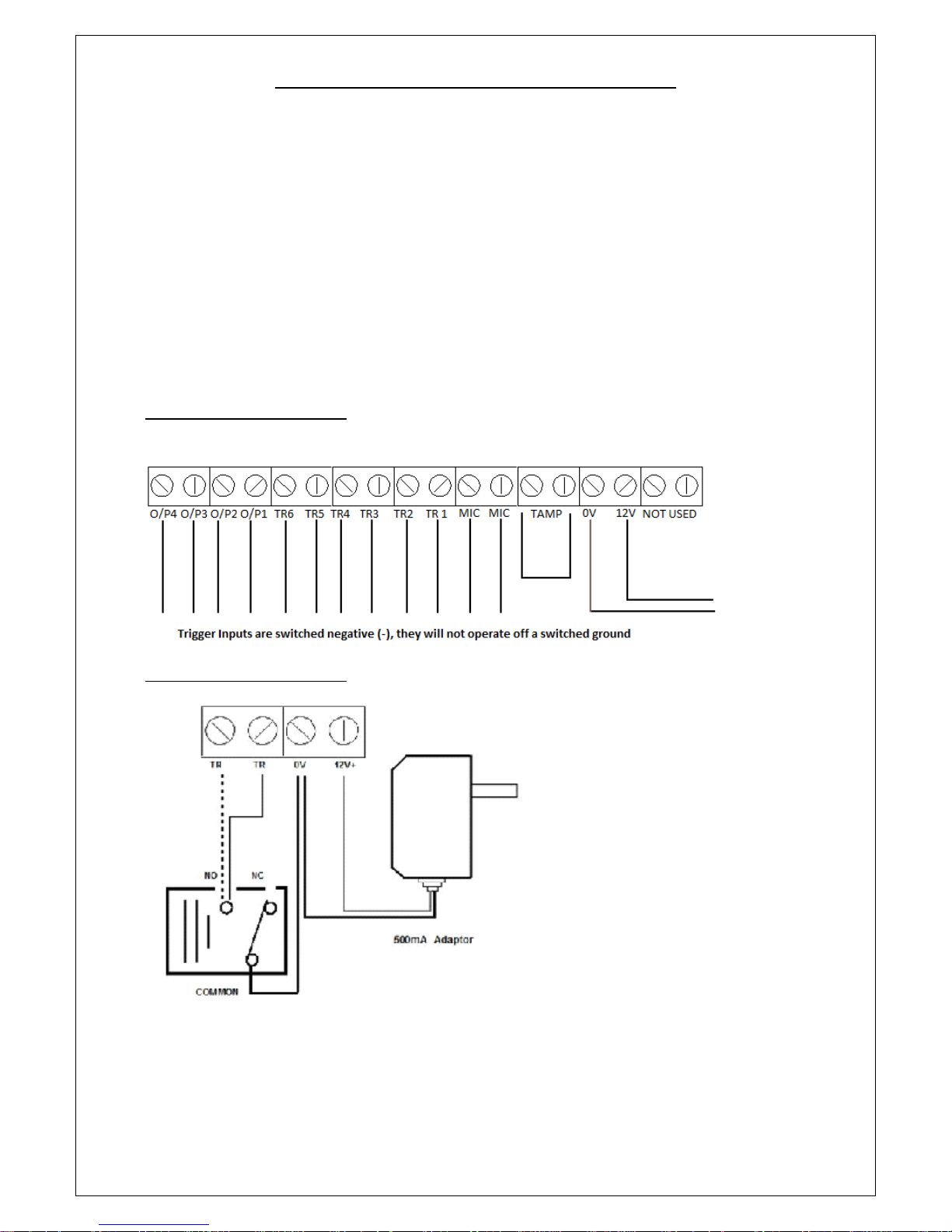
The Trigger terminals are for connection to a switched negative output of an Alarm System’s Bell or Siren (Fig 1
below). If such switched negative triggers are not available, connect the trigger inputs to a N.O. (normally
open) relay output with the relay common to OV (Fig 2).
The output terminals are all switched negative (max 100mA). Connect the connected device’s positive pin to
the 12V terminal and the device’s negative pin to the respective output terminal (O/P1, O/P2, O/P3 or O/P4).
The Power terminals are connected to a 12V power supply, either directly to an Alarm Control Panel’s 12V
supply or via a regulated 12V 500mA mains power adaptor.
The MIC terminals are for connection to an optional external microphone for improved “listen-in”.
IMPORTANT: The Tamper terminals are for connection to the N.C. (Normally Closed) tamper inputs on an
Alarm Control Panel. If they are not being used, please fit a loop of cable as shown.
FIG 1 – TERMINAL CONNECTIONS
FIG 2 – TERMINAL CONNECTIONS
Page 3
Page 4

ESSENTIAL PROGRAMMING
All Programming must be done when the Communicator is in the “OFF” position (1234 ESC).
HOW TO RECORD THE VOICE MESSAGES:
Quick guide: Press 1 2 3 4 > RECORD > 1 > ENTER, Record message now
(Note: 1 = message for Trigger 1; 2 = message for Trigger 2, etc; 0 = Test Message, if required.)
1. Key in the four digit user PASSWORD code (factory default 1234).
2. Press RECORD.
3. Press 1 (to record as the message for Trigger 1) or 2 (to record as the message for Trigger 2, etc) or 0
(to record the Test Message). If a Test Message is required, it then needs to be programmed as active
as a daily, weekly or monthly test call.
4. Press ENTER to start recording the message. You now have 10 seconds to record your message.
5. Press ENTER to stop the recording, or wait for the 10 seconds to end.
HOW TO PLAY BACK THE VOICE MESSAGES:
Quick guide: Press 1 2 3 4 > PLAY > 1 > ENTER to play back the recorded messages
(Note: 1 = the first message; 2 = the second message; 0 = Test Message.)
HOW TO CHANGE THE USER PASSWORD (Factory Default 1234):
Quick guide: Press 1 2 3 4 > PASSWORD > New Code > ENTER
1. Key in the four digit user <PASSWORD> code. Factory Default 1234.
2. Press PASSWORD.
3. The LCD will display “PASSWORD”.
4. Key in your new four digit code and press ENTER.
5. You have now changed to your new four digit password.
HOW TO PROGRAM PHONE NUMBERS:
You can enter a maximum of 9 Telephone Numbers for the Triggers – each number can be a maximum of 32 digits.
Quick guide: Press 1 2 3 4 > PROGRAM > 3 > ENTER > 1 > ENTER > Telephone Number > ENTER
1. Key in the four digit user PASSWORD code (Factory Default 1234).
2. Press PROGRAM > 3 > ENTER > “X”. The number “X” you press after the ENTER button will select the
position in the sequence you want that telephone number to dial (1 = 1st number called; 2 = 2nd
number called).
3. Key in the 1
st
telephone number.
4. Press ENTER to exit the programming mode.
5. Repeat the process until you have entered all the numbers you wish the Communicator to call once it
has been triggered (maximum 9 different numbers). You can repeat the same number(s) if you wish.
HOW TO DELETE PHONE NUMBERS:
Quick guide: Press 1 2 3 4 > PROGRAM > 3 > ENTER > 1 > ENTER > DELETE > ENTER
1. Key in the four digit user Password code (Factory Default 1234).
2. Press PROGRAM > 3 > ENTER. Select the position for the telephone number you want to delete (1 =
1st number called; 2 = 2nd number called), Press DELETE. The LCD display will show “DELETE”. Press
ENTER to delete or ESC to keep the number and exit programming.
HOW TO DESIGNATE TELEPHONE NUMBERS TO TRIGs 1, 2, 3, 4, 5 and 6 + THE TEST CALL:
(Factory Default – All numbers are called for each Trigger input and the Test Call.) Only these Telephone Numbers will be
called/SMS sent to on activation of the respective Trigger input.
Quick guide: Press 1 2 3 4 > PROGRAM > 6 > ENTER > X > ENTER > N > ENTER
1. Key in the four digit user Password code (Factory Default 1234).
2. Press PROGRAM > 6 > ENTER
3. Press 1 (for TRIG 1), or Press 2 (for TRIG 2), etc. Press 0 for the Test Call. Press ENTER
Page 4
Page 5
4. You will see numbers 123456789 illuminated in the Display. This indicates that all 9 telephone
numbers (or as many as have been programmed into the Communicator) will be called or sent an SMS
on that Trigger.
5. Press 1 – 9 to de-select that phone number from being dialled. You will now see a blank “ - “ where
that number was previously. Press ENTER to save the setting.
6. Repeat the process until you have designated all the numbers to each trigger. Remember that you
can designate all 9 numbers to each trigger or only some to one and some to the other.
IMPORTANT: The numbers shown on the LCD display are the phone numbers assigned to that trigger or to the
Test Call. (Pressing buttons 1 to 9 will toggle the numbers on/off on 1-9 respectively. If a number is not
shown, then it means that it will not be called.
Example: means that only telephone numbers 1, 2, 3, 7 and 9 will be dialled for that specific
trigger.
IMPORTANT: Whether a voice or SMS is sent on activation of a specific trigger. See “Advanced Programming”
- it also selects whether a voice message or SMS is sent on the Test Call. Note that some network providers
now require a voice message rather than data only to keep a Pay-As-You-Go SIM card active.
HOW TO CREATE AN SMS MESSAGE FOR A TRIGGER INPUT (DEFAULT MEMORY IS EMPTY):
Quick guide: Press 1 2 3 4 > PROGRAM > 9 > ENTER > 1 > ENTER > MESSAGE > ENTER
(“1” = Trigger Input 1 – 6 or “0” = Test Message. MESSAGE = 32 Digit Message including spaces.)
1. Key in the four digit user Password code (Factory Default 1234).
2. Press PROGRAM > 9 > ENTER
Display will show SMS MESS
Press 1 to program a message for Trigger 1 input; Press 2 to program a message for Trigger 2 input, etc.
The display will now be blank. Use the keys 1-0 on the keypad to enter letters or pronunciation marks.
Press each key continuously to obtain different letters as per standard telephone keypad. That means:
1 = “!” or “,” or “.” Or “1”; 2 = “a” or “b” or “c” or “2”; 3 = “d” or “e” or “f” or “3”, etc, etc.
The cursor will move automatically to the next letter approximately 2 seconds after you have made your entry.
Alternatively, Press the RECORD key to move the cursor to the left; Press the PLAY key to move the cursor to
the right. Press the DELETE key to the delete the letter over which the cursor is flashing. Press ENTER to save
your selection.
HOW TO SELECT WHETHER A TELEPHONE NUMBER RECEIVES A VOICE MESSAGE OR AN SMS OR BOTH:
(Factory Default – all telephone numbers receive a Voice Message only.)
Quick guide: Press 1 2 3 4 > PROGRAM > 0 > ENTER > 1 > ENTER > N > ENTER > 1 > ENTER
(N = Telephone Number 1,2,3,4,5,6,7,8 or 9; 1 = Voice, 0 = SMS; 2 = Voice & SMS.)
1. Key in the four digit user Password code (Factory Default 1234).
2. Press PROGRAM > 0 > ENTER > 1 > ENTER.
Display will show Voice or SMS
Press 1 to programme Telephone Number 1; Press 2 to programme Telephone Number 2, etc.
Page 5
1 2 3 - - - 7 9
Page 6

Display will show Voice or SMS 1
Voice
Press 0 to select that telephone number to receive an SMS only or Press 2 to select that telephone number to receive an
SMS and Voice message. Press 1 to return to the input sending a Voice message only.
Press ENTER to save selection.
Where both Voice messages and SMS are selected, then the Communicator will send all SMS’s out first, then start dialling
each number in sequence. Pressing # or * buttons will cancel continued voice message dial out or pressing 9 will open up
listen-in and cancel further dial out. Press ENTER to save selection.
HOW TO SELECT WHETHER THE COMMUNICATOR SENDS OUT A REGULAR TEST CALL OR SMS:
(Factory default – No Test Call or SMS.)
Quick guide: Press 1 2 3 4 > PROGRAM > 0 > ENTER > 2 > ENTER > 1 (or see below) > ENTER
(1 = Monthly; 2 = Weekly; 3 = Daily; 0 = No Test Call.)
1. Key in the four digit user Password code (Factory Default 1234).
2. Press PROGRAM > 0 > ENTER > 2 > ENTER
Display will show Test Call
No Test Call
Press 1 to select a monthly test call, 2 to select a weekly test call, 3 to select a daily test call and 0 to return to
no test call.
Display will show Voice or SMS 1
Monthly Test Call
Press ENTER to save your selection.
IMPORTANT: Most Pay-As-You-Go SIM cards will be disabled after a certain period if they are inactive (this period varies
according to the network provider), therefore, to stop this from happening, please enable the self-test feature. Some
service providers now require voice rather than data only to keep a Pay-As-You-Go SIM card enabled.
HOW TO SHOW THE SIM CARDS IMEI CODE:
Quick guide: Press 1 2 3 4 > PROGRAM > 0 > ENTER > 3 > ENTER
1. Key in the four digit user Password code (Factory Default 1234).
2. Press PROGRAM > 0 > ENTER > 3 > ENTER
Display will show IMEI Code
453218905632989
HOW TO SELECT WHETHER YOU WISH THE COMMUNICATOR TO FORWARD ON TO TELEPHONE NUMBER 1
ANY SMS THAT IT RECEIVES:
The reason for this is because some service providers will send a Pay-As-You-Go SIM card an SMS to warn when credit is
low.
(Factory Default – No Forwarding of an incoming SMS.)
Quick guide: Press 1 2 3 4 > PROGRAM > 0 > ENTER > 6 > 1 > ENTER
(0 = No Forwarding, 1 = Forwarding Active.)
1. Key in the four digit user Password code (Factory Default 1234).
2. Press PROGRAM > 0 > ENTER > 6 > ENTER
Page 6
Page 7

Display will show Call Forwarding
No call Forwarding
Press 1 to select Call Forwarding or 0 to return to No Call Forwarding.
Display will show Call Forwarding
Forwarding
Press ENTER to save your selection.
ADVANCED PROGRAMMING
HOW TO PROGRAM THE COMMUNICATOR TO GIVE A LOCAL AUDIBLE ALARM AS WELL AS SENDING A VOICE MESSAGE:
(Factory Default – Alarm Off)
Quick guide: Press 1 2 3 4 > PROGRAM > 1 > ENTER > 1 > ENTER (1 = Audible, 0 = Silent)
1. Key in the four digit user Password code (Factory Default 1234).
2. Press PROGRAM > 1 > ENTER
Display will show Alarm Sound
Silent
Press 1 to change to Audible, Press 0 to return to Silent, Press ENTER to save your selection.
HOW TO SET THE TIME THE AUDIBLE LOCAL ALARM WILL SOUND ON ACTIVATION:
(Factory Default – 3 Minutes.)
Quick guide: Press 1 2 3 4 > PROGRAM > 2 > ENTER > Time >ENTER (Alarm time is from 1M-99M)
1. Key in the four digit user Password code (Factory Default 1234).
2. Press PROGRAM > 2 > ENTER
Display will show Alarm Time
5 Minutes
Press digits 1-9 to set the time in minutes between 1-99 that you wish the alarm to sound on activation. We
recommend that you do not exceed a 20 minute alarm duration. Press ENTER to save your selection.
HOW TO SET TRIGGER DELAY TIMES:
(Factory Default – 0 Seconds – Instant.)
Set trigger delay time between 0, 30 and 60 seconds: As a false alarm prevention feature, this is the delay
between a trigger being activated and when the Communicator starts to dial out.
Quick guide: Press 1 2 3 4 > PROGRAM > 4 > ENTER > N > ENTER
(N = 0 OR 3 OR 6)
1. Key in the four digit user Password code (Factory Default 1234).
2. Press PROGRAM > 4 > ENTER
Display will show Trigger Delay
Instant
Press 3 to change to 30 seconds, Press 6 to change to 60 seconds, Press 0 to return to instant.
Press ENTER to save your selection.
HOW TO SET ARM DELAY TIMES:
(Factory Default – 0 Seconds – Instant.)
Set arm delay time between 0, 30, 60 and 90 seconds: This is the delay between the Communicator being
armed or primed and the time the triggers are active or ON. Default setting is 0 seconds, or no arm delay.
Note: If an arm delay time is programmed, then the ON symbol on the LCD displa y will flash throughout the
programmed time delay period.
Quick guide: Press 1 2 3 4 > PROGRAM > 5 > ENTER > N > ENTER
1. Key in the four digit user Password code (Factory Default 1234).
2. Press PROGRAM > 5 > ENTER
Page 7
Page 8

Display will show Exit Delay
Instant
Press 3 to change to 30 seconds, Press 6 to change to 60 seconds, Press 0 to return to instant.
Press ENTER to save your selection.
HOW TO SET THE ARM DELAY SOUND:
(Factory Default – Silent.)
Select whether you want a silent or audible sound on any arm delay.
Quick guide: Press 1 2 3 4 > PROGRAM > 7 > ENTER > 1 > ENTER
(1 = Audible; 0 = Silent)
1. Key in the four digit user Password code (Factory Default 1234).
2. Press PROGRAM > 7 > ENTER
Display will show Exit Delay Sound
Silent
Press 1 to change to Audible, Press 0 to return to Silent.
Press ENTER to save your selection.
HOW TO SELECT WHETHER AN OUTPUT IS 5 SECOND MOMENTARY (PULSED) OR TOGGLE LATCHING:
(FIRST ACTIVATION LATCHES OUTPUT ON, SECOND ACTIVATION TURNS IT OFF)
(Factory Default – Momentary.)
Quick guide: Press 1 2 3 4 > PROGRAM > 8 > ENTER > 1 > ENTER > N > ENTER > 1 > ENTER
(N = Output 1,2,3 or 4; 0 = Timed; 1 = Latched.)
1. Key in the four digit user Password code (Factory Default 1234).
2. Press PROGRAM > 8 > ENTER > 1 > ENTER
Display will show Output
Press 1 to program Output 1, Press 2 to program Output 2, etc.
Display will show Output 1
Timed
Press 1 to Latching Toggles, Press 0 to return to instant.
Press ENTER to save your selection.
HOW TO SELECT THE TIME OF A PULSED MOMENTARY OUTPUT:
(Factory Default – 5 Seconds.)
Quick guide: Press 1 2 3 4 > PROGRAM > 8 > ENTER > 2 > ENTER > N > ENTER > Time > ENTER
(N = Output 1,2,3 or 4 Alarm sound time is from 1 minute – 99 minutes)
1. Key in the four digit user Password code (Factory Default 1234).
2. Press PROGRAM > 8 > ENTER > 2 > ENTER
Display will show Timed Pulse Time
Press 1 to program Output 1, Press 2 to program Output 2, etc.
Display will show Output Time
5 Seconds
Press digits 1-9 to create a time in seconds that you wish to select as the time for that output to activate.
Press ENTER to save your selection.
HOW TO SELECT WHETHER AN OUTPUT IS EVENT (TRIGGER ACTIVATED) AS WELL AS USER ACTIVATED:
(Factory Default – User Activated Only)
Quick guide: Press 1 2 3 4 > PROGRAM > 8 > ENTER > 3 > ENTER > N > ENTER >1 > ENTER
(N = Output 1,2,3 or 4; 0 = User Activated only; 1 = User + Event/Trigger Activated.)
Page 8
Page 9

1. Key in the four digit user Password code (Factory Default 1234).
2. Press PROGRAM > 8 > ENTER > 2 > ENTER
Display will show Output Type
Press 1 to program Output 1, Press 2 to program Output 2, etc.
Display will show Output Type
User
Press 1 to select Output as activating on Trigger 1 (if selected, Output 1 will then activate on activation of
Trigger 1, Repeat to program Output 2 activating on Trigger 2, etc.). Press 0 to return to User Activation only.
Press ENTER to save your selection.
HOW TO TURN THE COMMUNICATOR ON/OFF LOCALLY OR REMOTELY
How to turn the Communicator ON: (Default ON. That means the Communicator will always be active or ON
when power is first applied or re-applied to it. Turn OFF to program and then turn back ON and leave ON)
From the Communicator: Quick guide: Press 1 2 3 4 > ENTER
1. Check that the voice message and at least one phone number has been programmed into the
Communicator.
2. Press 1 2 3 4 ENTER. The Communicator will show “ON” on the display.
3. The triggers will become active after the delay time you have set has expired (Default 0 seconds or
instant).
From a Telephone: Quick guide: Call the Communicator and Press 1 2 3 4 > #
1. Check that the voice message and at least one phone number has been programmed into the
Communicator.
2. Call the Communicator (telephone number of the SIM card that has been installed). You will hear a
long “beep” to indicate that the Communicator has answered. The Communicator’s display will read
“Call in”.
3. Press 1 2 3 4 (4 digit code) followed by the # key. You will hear 2 beeps to indicate that the
Communicator has been turned on and the Communicator will automatically hang up.
4. The triggers will become active after the delay you have set up has expired (default set at 0 seconds,
instant).
From a Text Message: Quick guide: Text the Communicator with 1 2 3 4 ># then press the return key
1. Check that the voice message and at least one phone number has been programmed into the
Communicator.
2. Text the Communicator (telephone number of the SIM card that has been installed) with the
message: 1 2 3 4 # - ensure you then press the return key before pressing send so the cursor on your
phone is flashing on the next line. The Communicator’s display will briefly show a number, being the
number of texts it has received to date.
3. The triggers will become active after the time you have set has expired (default set at 0 seconds,
instant).
Page 9
Page 10
How to turn the Communicator OFF: or to stop it dialling out.
From the Communicator: Press 1 2 3 4 ESC – Communicator will show OFF on the display. This will also stop
calls being sent out after it has been triggered.
From a Telephone: Quick guide: Call the Communicator and press 1 2 3 4 > *
1. Call the Communicator (telephone number of the SIM card that has been installed). You will hear a
long “beep” to indicate that the Communicator has answered. The Communicator’s display will read
“Call in”.
2. Press 1 2 3 4 (4 digit code) followed by the * key. You will hear 4 beeps to indicate that the
Communicator has been turned off and the Communicator will automatically hang up.
From a Text Message: Quick guide: Text the Communicator with 1 2 3 4 >* then press the return key.
Text the communicator (telephone number of the SIM card that has been installed) with the
message 1 2 3 4 * - ensure you then press the return key before pressing send so the cursor on your
phone is flashing on the next line. The Communicator’s display will briefly show a number, being
the number of texts is has received to date.
HOW TO STOP THE COMMUNICATOR DIALLING THE TELEPHONE NUMBERS IN SEQUENCE;
Quick guide: When the phone is answered, Press <#> or <*> on the receiving end’s telephone keypad to stop
the dialling sequence.
When the Communicator starts dialling, it will dial the first telephone number and repeat the pre -recorded
voice message three times. The number dialled will appear briefly on the display and the display will then
show the Telephone Number, in sequence, being called. If there is no response or acknowledgement (# or *
pressed) from that number, then it will dial the next number until all the programmed numbers for that trigger
are dialled. If there is no acknowledgement from any of the phone numbers, it will display “NO ANSWER”.
To stop this dial sequence, press the <*> key on the telephone keypad that is receiving the call. At that time,
the Communicator will stop its dialling sequence and the alarm (if programmed) will stop. If the local alarm
has been programmed as active, then pressing the <#> key will stop the dialling sequence, but the alarm will
continue to sound until timed out. In both cases, the Communicator will remain ON, waiting for any further
trigger.
You can also stop the dial sequence at the Communicator’s keypad by entering the 4 digit code and pressing
ESC. This will turn the Communicator OFF.
HOW TO OPEN “LISTEN-IN”
When answering a Voice Message from the Communicator: Quick guide: Press 9
1. If you wish to open “Listen-In” at any time, whilst receiving a voice message from the Communicator,
press 9 on your telephone keypad.
2. To close the “Listen-In”, simply hang up.
Page 10
Page 11

From a telephone: Quick guide: Call the Communicator and Press 1 2 3 4 > 9
1. Call the Communicator (telephone number of the SIM card that has been installed). You will hear a
long “beep” to indicate that the Communicator has answered. The Communicators display will read
“Call In”.
2. Press 1 2 3 4 (4 digit code) followed by the 9 key to open “Listen-In”. To close, simply hang up.
HOW TO RETURN THE COMMUNICATOR TO FACTORY DEFAULT
SETTINGS
(Note: this can only be done when the Communicator is in the OFF mode.)
From the Communicator: Quick guide: Press 1 2 3 4 > ESC > ENTER > 1 2 3 4 > ESC > ENTER
1. Ensure the Communicator is in the OFF mode.
2. Press 1 2 3 4 > ESC > ENTER. The display will read “Factory Default” – Press 1 2 3 4 > ESC > ENTER again to
confirm you wish to return to Factory Default Setting.
HOW TO TURN THE OUTPUTS ON AND OFF
The GJD710 has 4 Outputs that can be programmed:
1. User only (default setting) or Event Follower + User . “Event Follower” means Output 1 activates when trigger 1
is activated, Output 2 when trigger 2 is activated, and so on.
2. Whether the output is a 5 second pulsed momentary output or a toggle latching output. “Toggle Latching
Output” means that the output remains ON until a further command turns it OFF again. Note: if the output has
been programmed as a momentary output, a further programming section selects whether it remains On for a
time between 1 and 99 seconds before automatically turning Off.
User Activation of the Outputs
From the Communicator: Quick guide: Press 1 2 3 4 > 0 > 1 (the number of the output).
1. Press 1 2 3 4, followed by 0, followed by the number 1-4, being the number of the output you wish to turn ON
(Output 1 in this example).
2. The Communicator will show “Output 1” on the display.
3. The output will become active for the time which has been programmed (a time of between 1 and 99 seconds if
the output has been programmed as a momentary output or latching On until turned Off if it has been
programmed as a latching output).
4. To turn a Latching output off, Press 1 2 3 4, followed by 0, followed by the number 1-4, being the number of the
output you wish to turn off.
HOW TO INITIATE AN IMMEDIATE TEST CALL OR TEST SMS FROM
THE GSM COMMUNICATOR
If you wish to receive a Test Voice Call, you will first need to record a Test Message. See “How to record the Voice
Messages” on Page 4. If you wish to receive a Test SMS, you will first need to create a Test SMS (see Page 4). The Test Call
or SMS will be sent to those telephone numbers you have selected (default is all numbers will receive a test call). Select
whether you wish numbers to receive a Test Voice Call only, Test SMS only or both Voice Call and SMS (see Page 5). You
can cancel continued dial-out of the immediate Voice Message Test Call in the usual way by pressing * or # on your phone.
Page 11
Page 12
From a telephone: Quick Guide: Call the Communicator and press 1 2 3 4 > 5
1. Check that the Voice Test Call message and at least one phone number has been programmed into the
Communicator.
2. Check whether you wish all or some programmed telephone numbers to receive such Voice Test Call message
(default is all numbers).
3. Check whether you wish the telephone numbers to receive a Voice Test Call Message only or an SMS as well as a
Voice Test Call Message (default is a Voice Test Call Message only). If you wish any telephone numbers to receive
an SMS stating “Test”, program such numbers to receive an SMS as well (see Page 5).
4. Call the Communicator (telephone number of the SIM card that has been installed). You will hear a long “beep”
to indicate that the Communicator has answered. The Communicator’s display will read “Call In”.
5. Press 1 2 3 4 (4 digit code) followed by the 5 key. The Communicator will hang up and the selected telephone
numbers will then shortly receive an SMS first (if programmed to receive the same) followed by a Voice Test Call
message.
OTHER USEFUL INFORMATION
HOW TO TEST THE GSM NETWORK SIGNAL STRENGTH:
Whilst the Communicator is in the OFF mode (enter 4 digit code, default 1234 + ESC key), press ENTER to display the
network reception quality on the LCD display. A number between 0 and 7 will appear. The strongest reception quality is 7.
The Communicator should only be installed in a location where the signal strength display shows 2 or above. Move the
Communicator to a different location if the number is 1 or below. You can continue to check the network reception
strength at any time provide the Communicator is in the OFF mode. Note that you can also check signal strength by calling
the Communicator and entering your code + 7 once it has answered. The Communicator will then send an SMS with
current signal strength to Phone No 1 as programmed.
HOW TO CHANGE THE BACK-UP BATTERY (IF USED):
Important: It is recommended to change the back-up battery pack at least once a year, even if not low.
1. First make sure that the Communicator is OFF. Then release it from the wall.
2. Remove the battery door and remove the old battery. Re-insert a new 9V BATTERY (Lithium recommended).
3. Re-fit the battery door and hang the Communicator back on the wall.
Note of Caution:
1. Do not mount the Communicator in areas that are exposed to extreme heat or moisture, as this could adversely
affect the performance of the system.
2. Use only a damp cloth and general household cleaning agent to wipe the unit clean. Do not use turpentine,
thinners, gasoline or similar substances to clean the unit.
Page 12
Page 13
TROUBLE SHOOTING
Q
I have connected the Communicator to an Alarm Panel. The panel has activated, but there is no message appearing
on the Communicator’s LCD display and it is not dialling out.
A
Check the following carefully:
I. Does the Communicator have a 12V supply – either from the panel or via a 500ma 12V mains adaptor?
II. Does the Communicator have a SIM card fitted? The words “On GSM Ready” should be showing in the
display to indicate that a SIM card has been fitted and that a network has been found.
III. Have you fitted your SIM card correctly? The SIM card must be fitted firmly into the holder in the correct
orientation.
IV. Have you made the correct connections to the Trigger 1 and 2 inputs (either switched negative or relay)?
V. Is the Communicator On/Armed? Remember that if you have been programming, then it will have been in
the Off mode and you will have to go back to On/Armed mode again. Enter your 4 digit code + Enter to turn
On/Armed.
VI. Has your SIM card been disabled by the Network Provider? Most Pay-As-You-Go SIM cards will be disabled
after a certain period if they are inactive. Some Network Providers now also require voice usage rather
than text usage to continue activation. Check first whether the Network Provider you are using accepts a
regular text message to continue activation and over what period of time. Then enable a Self-Test Text
Message (see Pages 4 & 6). If your Network Provider requires voice usage only, consider changing Providers
or use a Contract SIM.
Q
The Communicator’s input has been activated correctly and a message has appeared in its display to
indicate this, however, the voice message is not being received by the number it is meant to be dialling.
A
Check the following carefully:
I. Have you activated the correct Communicator trigger? You may have programmed different
numbers to call out for Trigger 1 and Trigger 2.
II. See Page 4: have you entered the correct telephone number to call and/or entered a wrong digit
by mistake?
III. If you think the Communicator should be dialling a particular number, have you actually de-
selected that number for that trigger by mistake? (see Pages 4 & 5) To check the numbers that
are being dialled in sequence for Trigger 1, press 1234 (code) > Program > 6 > Enter > 1. You
should now see various numbers between 1 and 0 illuminated. If a number is unlit it means it is
not being dialled for Trigger 1. Toggle numbers on/off by pressing that number on the keypad. A
number must be shown if it is being dialled for that trigger.
Q
The Communicator’s input has been activated correctly and a message has appeared in its display to
indicate this, however, it is not then dialling out and an error message is appearing on the LCD display.
A
Check the following carefully:
I. Have you programmed at least one telephone number to the Communicator? If the
Communicator is showing a “no answer message” in the display it means no telephone number
has been programmed. Press 1234(code)+ESC to exit. Then, go to Page 4 and enter at least one
telephone number as instructed.
II. Have you deleted a telephone number by mistake? See Page 4 - To check whether the 1
st
telephone number you think you have programmed in is in the Communicator’s memory
correctly, Press 1234(code)>Program>3>Enter>1>Enter. You should now see that telephone
number. Press Enter again to Exit programming. If you don’t see a telephone number there,
enter the number again and press Enter to exit. DO NOT PRESS ESC TO EXIT AS THIS WILL DELETE
THAT NUMBER.
III. Have you de-selected a number to be dialled out in sequence for that trigger by mistake? See
Pages 4 & 5 - To check the numbers that are being dialled in sequence for Trigger 1, press
1234(code)>Program>6>Enter>1. You should now see various numbers between 1 and 0
illuminated. If a number is unlit, it means it is not being dialled for Trigger 1. Toggle numbes
on/off by pressing that number on the keyboard. A number must be shown if it is being dialled
for that trigger.
IV. Is the Communicator in a location where it can obtain a good GSM signal? Check the Network
signal strength by pressing ENTER (you can do this whilst the Communicator is both in the ON
and OFF modes). The Communicator should be installed in a location where the signal strength
displayed shows at least 2 or above. Move the Communicator to a different location in the
premises or use an alternative network SIM card.
Q
I can’t cancel the remote dial-out remotely by pressing, on the remote telephone hand-set, either *
(cancel dial out and alarm sound if programmed) or # (cancel dial out only, alarm sound will continue until
time out).
A
Have you waited until the message has ended? You cannot cancel until it has been played to you at least
once.
Page 13
Page 14

NOTES
 Loading...