

GJD D-TECT Walktester GJD380 Installation & User Manual
D-TECT Walktester
GJD380 Installation Tool
Installation & User Guide
The D-TECT WalkTester (Fig.3) is an installation tool that will help the
installer set up GJD D-TECT’s on site.
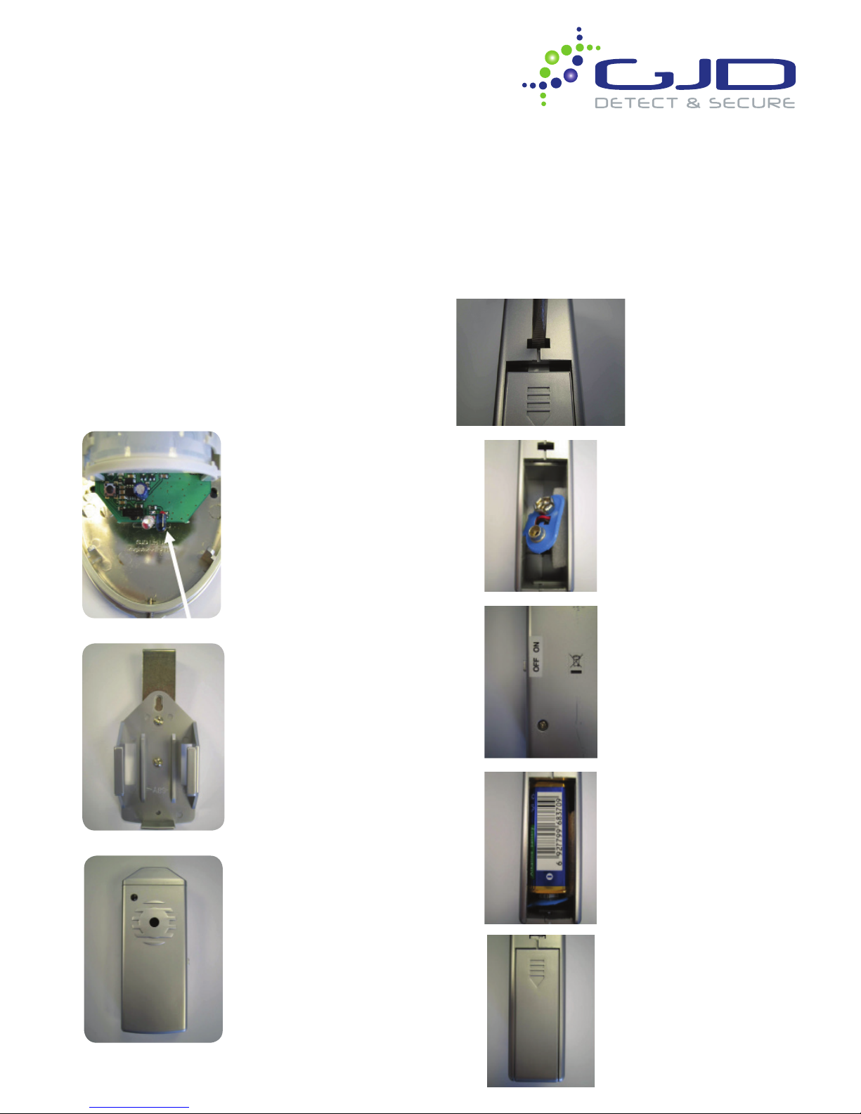
*Each D-TECT external detector has been tted with and infra-red LED
emitter. When activation occurs the transmitter sends a signal. This
signal is then received by the WalkTester and a very bright white LED
on the WalkTester ashes, also a Piezo speaker sounds.
Under normal situations both the LED and the sounder can be seen
and heard up to 50 meters.
*Please note that some of the earlier versions of D-TECT’s were not
tted with IR transmitters and so the WalkTester will not work with
these units. To verify please take the cover off the D-TECT and look
at the **bottom of the circuit board for a blue IR LED (Fig.1). If this
is present then the WalkTester will be able to communicate with the
D-TECT.
Fig.1 D-TECT IR emitter
NOTE: For D-TECT 2 and
D-TECT 50 the IR LED is on
the front of the circuit board.
On the D-TECT 3 it is on the
rear PDB.
Fig.2 WalkTester holder &
bracket
Fig.3 WalkTester
Powering The Walktester
The D-TECT WalkTester comes with a mounting bracket / holder
(Fig.2).
First t a PP3 battery into the WalkTester battery compartment (Fig.5
& Fig.7). This is done by removing the battery compartment cover as
shown in Fig.4. Please ensure that the on/off switch on the WalkTester
is set to the ‘off’ position while connecting the battery (Fig.6). When
tted close the battery compartment and the WalkTester is ready for
use (Fig.8).
Fig.4. Removing battery
compartment cover
Fig.5. PP£ battery connector
Fig.6.6 On / Off switch
Fig.7. PP3 battery tted
Fig.8. Cover replaced
Using The Walktester
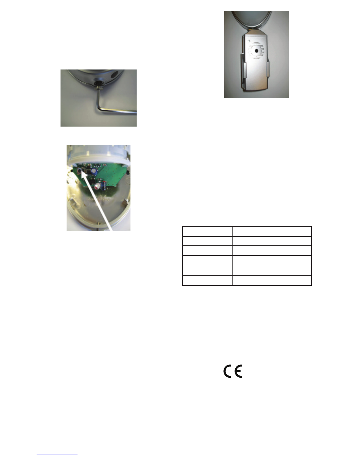
Remove the cover from the D-TECT housing by loosening
the stainless steel screw at the bottom of the D-TECT
(Fig.9). This will allow access to the programming button
shown in Fig.10 (and to also verify the presence of the Blue
IR Emitting LED).
The WalkTester will illuminate and sound every time the
D-TECT is activated.
For more information on the walk test procedure please refer
to the relevant D-TECT manual.
When nished testing, turn off the WalkTester and remove it
and the holder from the D-TECT.
Tighten the screw on the base of the D-TECT. The GJD
D-TECT external detector is now ready.
SPECIFICATIONS
POWER 9VDC (PP3 Cell)
CURRENT Standby: 0.5mA
OPERATING TEMP -20°C to +55°C
Protection Please note that the WalkTester is
not waterproof and should not be
used in we weather conditions
Dimensions 118 x 47 x 25mm
APPROVALS
The manufacturer declares that the product supplied is
compliant with the provisions of the EMC Directive 89/336/
EEC amended 92/31/EEC for Electromagnetic Compatibility,
and the Restriction of Hazardous Substances Directive
(RoHS) 2002/95/EC. A Declaration of Conformity in
accordance with the above directives is held on le with
the manufacturer.
CE MARK
Fig.11 WalkTester in holder and tted
to D-TECT, ready for walk testing
Fig.9. D-TECT cover and screw
Fig.10. D-TECT programming button
Place the D-TECT into ‘walk test’ mode by pressing the
programme button once (Fig.10). The D-TECT’s clear LED
will then ash out its current settings. Wait for the ashing
sequence to nish. The D-TECT is now in walk test mode
and will remain in that state for ve minutes after the last
detection, where after it will revert to normal mode. Walk
test can be cancelled at anytime by pressing the D-TECT
programme button twice.
REPLACE THE D-TECT COVER and place the WalkTester
in the metal holder.
Slightly loosen the stainless steel screw on the bottom of the
D-TECT, just enough so that the drilled tab on the WalkTest-
er bracket can slide around the screw thread. Then gently
tighten the screw to hold the WalkTester and holder in place
(Fig.11). Note the WalkTester can be orientated around the
base of the D-TECT detector within 180 degree
so as to allow for visibility during walk testing. Turn the
WalkTester on.
 Loading...