

GJD D-TECT Pet Immune GJD370, D-TECT Pet Immune GJD371, D-TECT Pet Immune GJD372 User Manual
Page 1

D-TECT Pet Immune
GJD370/371/372 Motion Detector
INTRODUCTION
An event trigger utilising two independent passive infrared
detectors and a microwave sensor. Both PIR sensors and
the microwave have to trigger before the detector signals
an alarm. The high precision, very reliable presence
detector has been designed for use within monitored
installations and will alarm if tampered by masking.
The integral dual axis tilt sensor allows 180° of pan and
30° tilt. This increases the speed of the outdoor installation
and provides incredibly accurate aiming of the detection
pattern. The electronics module is acrylic coated for
additional component stability. It is encased in a vandalresistant high impact ABS housing with a UV stabilised
translucent front cover ensuring the sensor is impervious
to and unaffected by weather conditions. Additionally the
combination of precision electronics, digital white light lter
and double shielding eliminates false alarms from the sun
and other visible light sources.
The Pet Immune design gives a neat and professional
appearance with no visible indication of the orientation of
the detector head, and totally hides the wiring.
QUICK INSTALLATION GUIDE
Apply supply voltage to the unit, the amber led ashes 10
times, then the blue LED ashes 3 times.
The detector takes approximately 2-3 minutes to settle. The
walk test led is enabled for 5 minutes after power is applied
THE FRONT COVER MUST BE FITTED WHEN WALK
TESTING
FACTORY SETTINGS ARE:
1 RANGE 15 METRES
2 PULSE COUNT 1
3 LED OFF
When enabled the D-TECT Pet Immune has four LED
indicators.
Green – Bottom PIR
Red – Top PIR
Blue - Alarm output, both PIRs and microwave detection
Amber - Anti-Mask detection
ANTI-MASKING CIRCUIT
The cover must be tted before applying power to the
detector.
During the rst 10 seconds after power has been
connected, the amber LED ashes and the anti-masking
circuit starts to self-calibrate. The amber LED indicates
when the detector is covered, but the relay contacts do not
operate until the unit has been covered for 60 seconds.
SEQUENCE FOR CORRECT AM OPERATION
1. Make connection and replace cover.
2. Apply 12 volts power. Amber LED Flashes 10 times - self
calibration completed.
3. Cover detector for 60 seconds. When anti-mask
detection is continuous for 60 seconds the normally closed
relay will open until anti-mask detection is cleared.
STAGE 1 - Mounting the unit
WARNING
• NYLON WASHERS PROVIDED MUST BE USED WITH
SCREWS
• ENSURE CABLE ENTRY AND SCREW HOLES ARE
SEALED WITH WATER BASED SEALANT
• DO NOT USE SILICONE BASED SEALANT
To reduce the possibility of the microwave circuit being
affected it is recommended to leave a minimum space of
3 metres between D-TECT Pet Immune sensors when
mounted alongside each other. When facing each other
a minimum space of 15 metres is recommended. It is
possible to mount the units back to back however when
detectors are mounted in close proximity to one another it
is advisable to carry out a walk test to ensure that external
objects are not inuencing the microwave circuit.
- During installation the electronics must be protected
against water, as trapped moisture can affect or damage
the unit.
1. Using the template provided drill the wall to accept the
two xing screws, the cable entry and the tamper cup (if
used). See g 1 and 2.
Note: We recommend using the tamper cup on uneven wall
surfaces.
2. Remove the cover assembly by loosening the locking
screw. The cover hinges from the top and lifts out of the
location slot. See g 3.
3. Feed standard 8 core alarm cable into the cable entry;
bare the wires and connect to the terminal block as shown
in g 7. Screw the unit to the wall ensuring that the tamper
pin is correctly located and that the tamper switch
is closed. See g 4 and 5. To aid installation, two spare
tamper feet are provided. One is 1mm longer and the other
is 2mm longer than the tamper foot originally tted. The
tamper foot is a push t and can be removed by carefully
pulling it from the pin. See g 2.
4.When the detector has been aligned to suit the
installation, replace the front cover and lock as shown. See
g 6.
Page 2
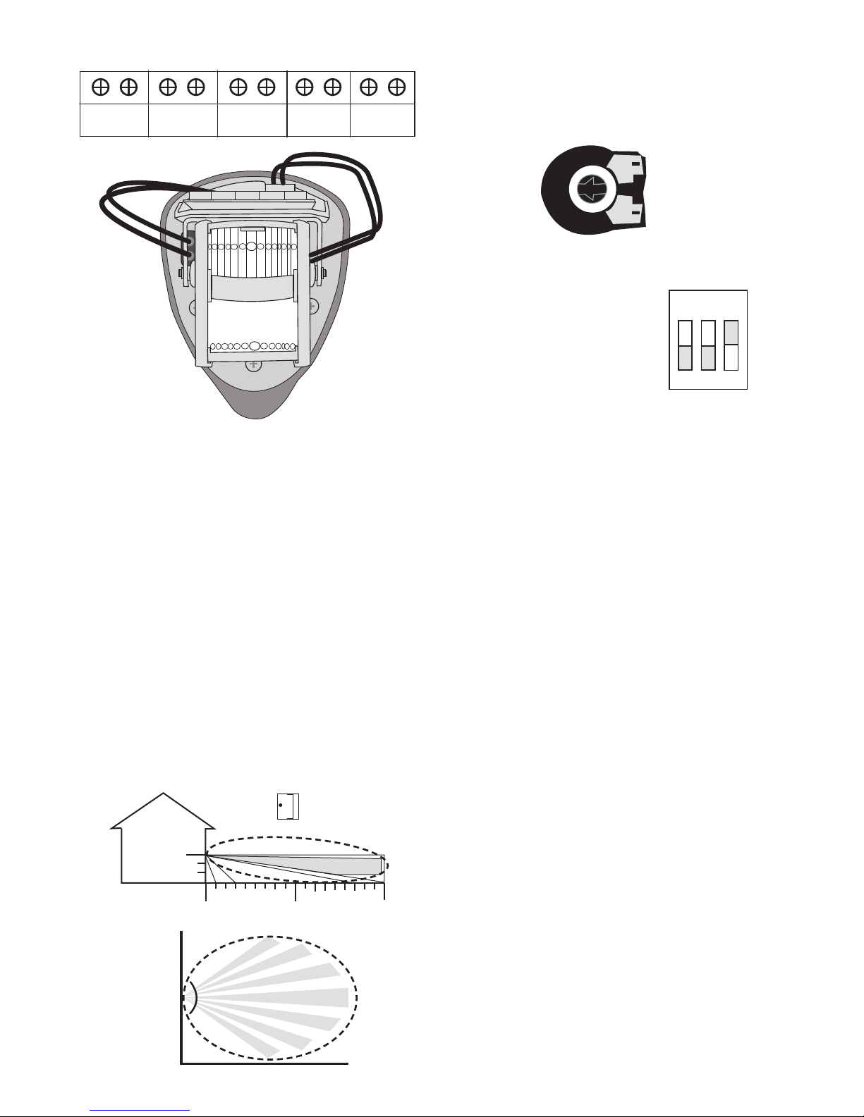
STAGE 2 - Connecting the Unit
A/M
ALARM/NC
ALARM/NO
TAMPER
+ -
9-15
VDC
STAGE 3 - Multibeam Alignment & Masking
The GJD lenses tted to the D-TECT detector produce 7
long range beams and 7 medium to short range curtain
beams. Movement across the beams produces the best
response and range for the PIRs, whilst movement towards
the detector produces the best response for the microwave
sensor. The unit detects the changes in heat and
movement in the beam pattern, therefore items such as
trees, shrubs, ponds, boiler ues and large animals should
be considered when positioning the detector.
The detector module is tted with two sliding shutters to
reduce the detection angle. An additional set of curtains
is provided should the beam pattern need to be narrowed
even further e.g. if the minimum detection angle of 10
degrees is required.
The curtains are tted to the pan and tilt module as
indicated in g 8. Each section of the detectors lens gives a
coverage pattern of around 10 degrees.
70º
12m
15m
12m
0m
0 10 15
1.8m
0 deg
STAGE 4 - Programming
The user can individually congure the detector’s settings.
LED Monitor
SW3 OFF = LEDs Disabled
SW3 ON = LEDs Enabled
STAGE 5 - Walk Test
The range of the detector increase without the front
protective cover. Therefore the front cover must be tted
to establish the correct beam pattern alignment and when
testing the outputs. Use the programming chart to adjust
the range as necessary and pan and tilt the lens module
over the eld of view to obtain the correct coverage area.
Walk test is enabled for ve minutes after the power is
connected. During this time the LEDs are enabled. After
there has been no detection for ve minutes the walk
test will cancel. The LED indicators can be permanently
enabled by turning SW3 to ON.
STAGE 6 - OPTION Denitions
PULSE COUNT
This is the number of times the unit has to detect on both of
its sensors before signaling an output.
LED MONITOR
LED Off - LED disabled.
LED on - LEDs signal a detection.
N/OPEN & N/CLOSED
These are magnetically immune volt free relay contacts
used to trigger alarm inputs on connected equipment.
The contacts are rated at a maximum of 24 AC/DC @
50mA.
ACCESSORIES
GJD is able to supply the following accessory to aid
installations:
GJD305 Pole mount clamp
ADJUST RANGE
MAX
MIN
SET PULSE COUNT
ON
1 2 3
SW1 OFF SW2 OFF = 1
SW1 ON SW2 OFF = 2
SW1 OFF SW2 ON = 3
SW1 ON SW2 ON = 4
Page 3

SIMPLIFIED EU DECLARATION OF CONFORMITY
Hereby, GJD Manufacturing Ltd declares that the radio
equipment type GJD370/GJD371/GJD372 D-TECT Pet
Immune Detector is in compliance with Directive 2014/53/
EU.
The full text of the EU declaration of conformity is available
at the following internet address: gjd.co.uk
Detection Area Up to 15m selectable
Coverage 10-70 degrees detection angle
Adjustment 180 degree pan + 30 degree tilt
Fresnel Lens 14 zones for each Pyro pair, which can be masked with the curtain sliders
Customised Optics Double silicon shielded dual element eliminates 50,000 Lux of White-Light
Microwave Module Operating Frequency. Country dependent GJD370 10.525 GHz
GJD371 10.587 GHz GJD372 9.9GHz
Outputs Silent solid state magnetically immune
N/OPEN Detection Alarm Volt free relay signal contact 24VAC/DC @ 50mA with
an integral 25R series resistor
Alarm time 5 seconds
N/CLOSED Detection Alarm Volt free relay signal contact 24VAC/DC @ 50mA with
an integral 25R series resistor
Alarm time 5 seconds
A/M Anti-Mask Detection Volt free relay signal contact 24VAC/DC @ 50mA with
an integral 25R series resistor
Tamper Front and rear switches Volt free signal contact 24VAC/DC @ 50mA
LED Indication 1 x Red - Top PIR
1 x Green - Bottom PIR
1 x Amber - Anti-Mask
1 x Blue - Alarm
Power Input 9 to 15 VDC
Current 15mA (12V nominal)
Pulse Count 1 - 2 - 3 - 4
Temp Compensation Digital sensitivity adjustment
Control Digital microprocessor
Walk Test Output test mode with LED indication
Operating Temp -20ºC to +55º C
Conformally coated electronics for increased stability
Housing High impact ABS
Protection Rating IP65
Dimensions 145 x 120 x 115 mm
Weight 280grams NET, 410 grams GROSS
Mounting Height Variable from 1.2 metres up to 1.8 metres
CE Mark
SPECIFICATIONS
Page 4

1
2
3
4
Page 5

5
6
7
A/M
ALARM/NC
ALARM/NO
TAMPER
+ -
9-15
VDC
8
9
CLICK CLICK
Page 6

Unit 2 Birch Business Park, Whittle Lane, Heywood, Greater Manchester, OL10 2SX, UK
www.gjd.co.uk info@gjd.co.uk +44 (0) 1706 363 998
ENGINEER NOTES
 Loading...