

Page 1

INTRODUCTION
A CCTV event trigger utilising two independent passive
infrared detectors combined in a T05 package and a
microwave sensor. Both PIR sensors and the microwave
have to trigger before the detector signals an alarm. The
high precision, very reliable presence detector has been
designed for use within CCTV installations and will alarm if
tampered by masking.
The integral dual axis tilt sensor allows 180° of pan
and 90° tilt. This increases the speed of the outdoor
installation and provides incredibly accurate aiming of
the detection pattern. The electronics module is acrylic
coated for additional component stability. It is encased in
a vandal-resistant high impact zinc alloy housing with a
UV stabilised translucent front cover ensuring the sensor
is impervious to and unaffected by weather conditions.
Additionally the combination of precision electronics,
digital white light lter and double shielding eliminates
false alarms from the sun and other visible light sources.
The DUAL TECH AM design gives a neat and
professional appearance with no visible indication of the
orientation of the detector head, and totally hides the
wiring.
QUICK INSTALLATION GUIDE
Apply supply voltage to the unit, the amber led ashes 10
times, then the blue LED ashes 3 times.
The detector takes approximately 2-3 minutes to settle.
The walk test led is factory set to OFF. Pressing the
program button once will enable the walk test LED for 5
minutes.
THE FRONT COVER MUST BE FITTED WHEN WALK
TESTING
FACTORY SETTINGS ARE:
1 RANGE 30 METRES
2 PULSE COUNT 1
3 LED OFF
When enabled the D-TECT DUAL TECH AM has four LED
indicators.
Green - Microwave detection
Red - Both PIRs detection
Blue - Alarm output, both PIRs and microwave detection
Amber - Anti-Mask detection
ANTI-MASKING CIRCUIT
The cover must be tted before applying power to the
detector.
During the rst 10 seconds after power has been
connected, the amber LED ashes and the anti-masking
circuit starts to self calibrate. The amber LED indicates
when the detector is covered, but the relay contacts do not
operate until the unit has been covered for 60 seconds.
SEQUENCE FOR CORRECT OPERATION
1. Make connection and replace cover.
2. Apply 12 volts power. Amber LED Flashes 10 times self calibration completed.
3. Cover detector for 60 seconds. When anti-mask
detection is continuous for 60 seconds the normally closed
relay will open until anti-mask detection is cleared.
STAGE 1 - Mounting the unit
- During installation the electronics must be protected
against water, as trapped moisture can affect or damage
the unit.
1. Using the template provided drill the wall to accept the
two xing screws, the cable entry and the tamper cup (if
used). See g 1 and 2.
Note: We recommend using the tamper cup on uneven
wall surfaces.
2. Remove the cover assembly by loosening the locking
screw. The cover hinges from the top and lifts out of the
location slot. See g 3.
3. Feed standard 8 core alarm cable into the cable entry;
bare the wires and connect to the terminal block as shown
in g 7. Screw the unit to the wall ensuring that the tamper
pin is correctly located and that the tamper microswitch
is closed. See g 4 and 5. To aid installation, two spare
tamper feet are provided. One is 1mm longer and the
other is 2mm longer than the tamper foot originally tted.
The tamper foot is a push t and can be removed by
carefully pulling it from the pin. See g 2.
4. Always ensure when replacing the electronics module
that the LED is facing forward so as to ensure correct
alignment of the beam pattern. (Refer section titled
“Multibeam Alignment & Masking”).
5. When the detector has been aligned to suit the
installation,replace the front cover and lock as shown. See
g 6.
D-TECT Dual Tech
GJD360/AM Movement Detector
Page 2
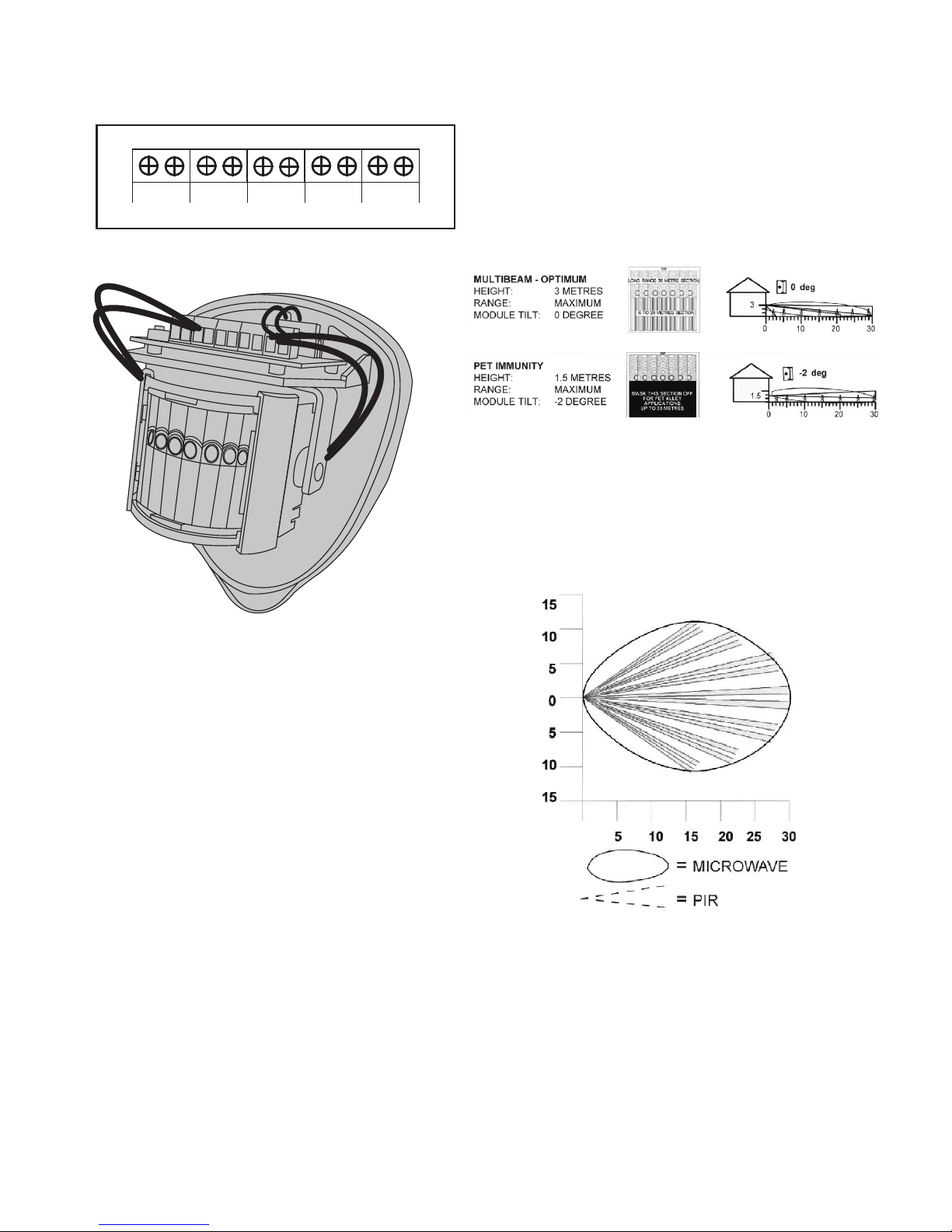
The curtains are tted to the pan and tilt module as
indicated in g 8. Each section of the detectors lens gives
a coverage pattern of around 10 degrees.
When mounting higher than boundary fences rotate the
module and mask off any beams, vertically or horizontally,
that fall outside the area being covered. Use portions of
the self-adhesive silver mask applied to the rear, smooth
side, of the lens. Always replace the lens the correct way
up to ensure exact beam pattern coverage (the top of the
Fresnel lens is marked - TOP). See g 9.
When mounted at heights above 3 metres there could be
a signicant reduction in the range of detection and the
target will have to move a greater distance within the eld
of view before an alarm is generated.
STAGE 2 - Connecting the Unit
STAGE 3 - Multibeam Alignment & Masking
The GJD multifunction lens tted to the D-TECT detector
produces 7 long range beams and 7 medium to short
range curtain beams. Movement across the beams
produces the best response and range for the PIRs,
whilst movement towards the detector produces the best
response for the microwave sensor. The unit detects
the changes in heat and movement in the beam pattern,
therefore items such as trees, shrubs, ponds, boiler ues
and animals should be considered when positioning the
detector.
The detector module is tted with two sliding shutters to
reduce the detection angle. An additional set of curtains
is provided should the beam pattern need to be narrowed
even further e.g. if the minimum detection angle of 10
degrees is required.
A/M
ALARM/NC TAMPER
ALARM/NO
+ -
9-15 VDC
Beam Pattern
Page 3
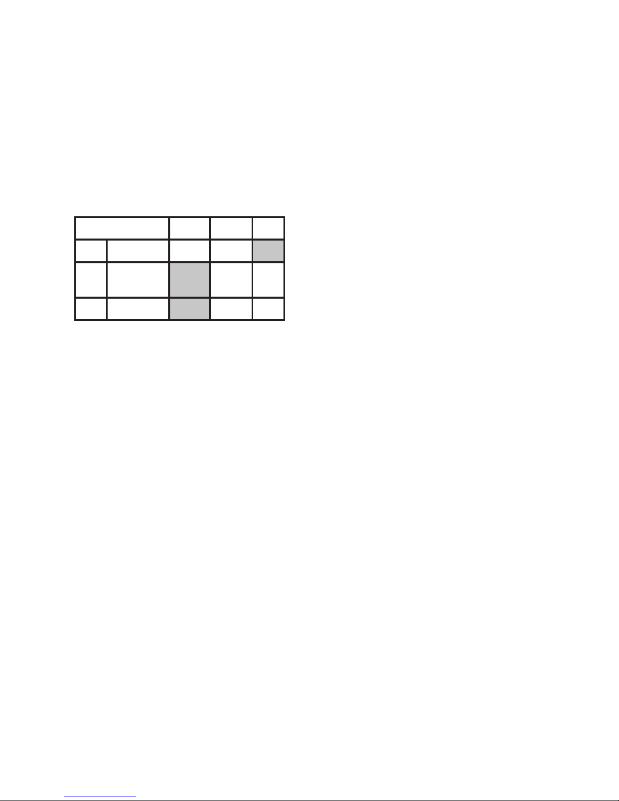
STAGE 4 - Programming
The user can individually program a number of
congurable settings as illustrated in the programming
chart. Factory settings are shown as shaded boxes.
Changes to the existing settings can easily be made. To
reset the factory settings simply remove power from the
detector, press and hold the program button (see g 10)
whilst temporarily applying power to the detector: either
before installation, with a PP3 battery, or by applying
12 volts to the unit on site. The Amber LED will ash 10
times, the blue LED will ash 3 times then the blue LED
will ash rapidly then release the program button.
PROGRAMMING CHART
To change any of the D-TECT settings :
1. Press the program button as shown in g.10 for the
number of the Option to change i.e. once for range, twice
for pulse count, three times for LED.
2. Wait four seconds until the blue LED indicator goes off.
3. The indicator will then ash out the existing setting.
4. To change the setting for that option, press the button
the number of times required for the new setting.
5. The indicator blinks twice and the changes are stored.
Any alterations made to the D-TECT settings are stored in
the detector’s non volatile memory.
EXAMPLE
To change the LED setting from OFF to ON.
1. Press the program button three times and release the
button.
2. Wait until the indicator goes off.
3. The indicator will now ash once.
4. Press the program button twice and release the button.
5. The indicator ashes twice showing that the option has
been stored and the detector returns to normal operation.
1 2 3
1 Range m 10 20 30
2 Pulse
Count
1 2
3 LED OFF ON
SETTING
OPTIONS
STAGE 5 - Walk Test
The range of the detector increase without the front
protective cover. Therefore the front cover must be tted
to establish the correct beam pattern alignment and when
testing the outputs. Use the programming chart to adjust
the range as necessary and pan and tilt the lens module
over the eld of view to obtain the correct coverage area.
When the ‘program’ button is pressed momentarily the
blue indicator lights and pulse count ‘1’ is automatically
selected. The unit can then be aligned. The blue indicator
will light on the D-TECT every time a detection takes
place. This test mode will automatically cancel ve
minutes after last detection. Alternatively, remove the
power and then re-apply.
STAGE 6 - OPTION Denitions
PULSE COUNT
This is the number of times the unit has to detect on both
of its sensors before signalling an output.
LED MONITOR
LED Off - LED disabled.
LED on - LEDs signal a detection.
N/OPEN & N/CLOSED
These are magnetically immune volt free relay contacts
used to trigger alarm inputs on connected equipment.
The contacts are rated at a maximum of 24 AC/DC @
50mA.
ACCESSORIES
GJD is able to supply the following accessories to aid
installations:
GJD304 Conduit cable entry adaptor ring
GJD305 Pole mount clamp
GJD380 Walk tester
Page 4

Figure 1
Optional for Tamper Cup
Cable Holes
Template
Figure 2
Figure 3
Figure 4
Figure 5 Figure 6
Page 5

Figure 7 Figure 8
A/M
ALARM/NC TAMPER
ALARM/NO
+ -
9-15 VDC
Figure 9 Figure 10
A/M
ALARM/NC TAMPER
ALARM/NO
+ -
9-15 VDC
PROGRAM
Program Button
Blue LED
Page 6

Detection Area Programmable between 10 & 30m
Coverage 10-70 degrees detection angle, 30m x 30m coverage max.
Adjustment 180 degree pan + 90 degree tilt
Fresnel Lens 28 zones for each Pyro pair, which can be masked with the curtain sliders
Customised Optics Double silicon shielded quad element eliminates 50,000 Lux of White-Light
Microwave Module Operating Frequency. Country dependent GHz 10 dBm EIRP
Outputs Silent solid state magnetically immune
No. 1 N/OPEN Volt free relay signal contact 24VAC/DC @ 50mA
with an integral 25R series resistor
Alarm time 5 seconds
No.2 N/CLOSED Volt free relay signal contact 24VAC/DC @ 50mA
with an integral 25R series resistor
Alarm time 5 seconds
Power Input 9 to 15 VDC
Current 15mA (12V nominal)
Pulse Count 1 - 2
Temp Compensation Digital sensitivity adjustment
Control Digital microprocessor - non volatile memory
Walk Test Output test mode with LED indication
Operating Temp -20ºC to +55º C
Conformally coated electronics for increased stability
Housing High impact zinc alloy
Protection Rating IP55
Dimensions 145 x 120 x 115 mm
Weight 750grams NET, 880 grams GROSS
Mounting Height Variable - optimum height 3 metres
Cable <200m Utilising all three outputs (incl. tamper) - 8 core 7/0.2mm
Cable <500m Utilising all three outputs (incl. tamper) - 8 core 16/0.2mm
CE Mark
SIMPLIFIED EU DECLARATION OF CONFORMITY
Hereby, GJD Manufacturing Ltd declares that the radio equipment type GJD360AM Dualtech Anti-Mask Detector
is in compliance with Directive 2014/53/EU.
The full text of the EU declaration of conformity is available at the following internet address: gjd.co.uk
Page 7

Unit 2 Birch Business Park, Whittle Lane, Heywood, Greater Manchester, OL10 2SX, UK
www.gjd.co.uk info@gjd.co.uk +44 (0) 1706 363 998
ENGINEER NOTES
 Loading...