

Page 1
Clarius
LED Illuminators
Clarius® PLUS
Infrared & White Light LED Illuminators
IR WL
®
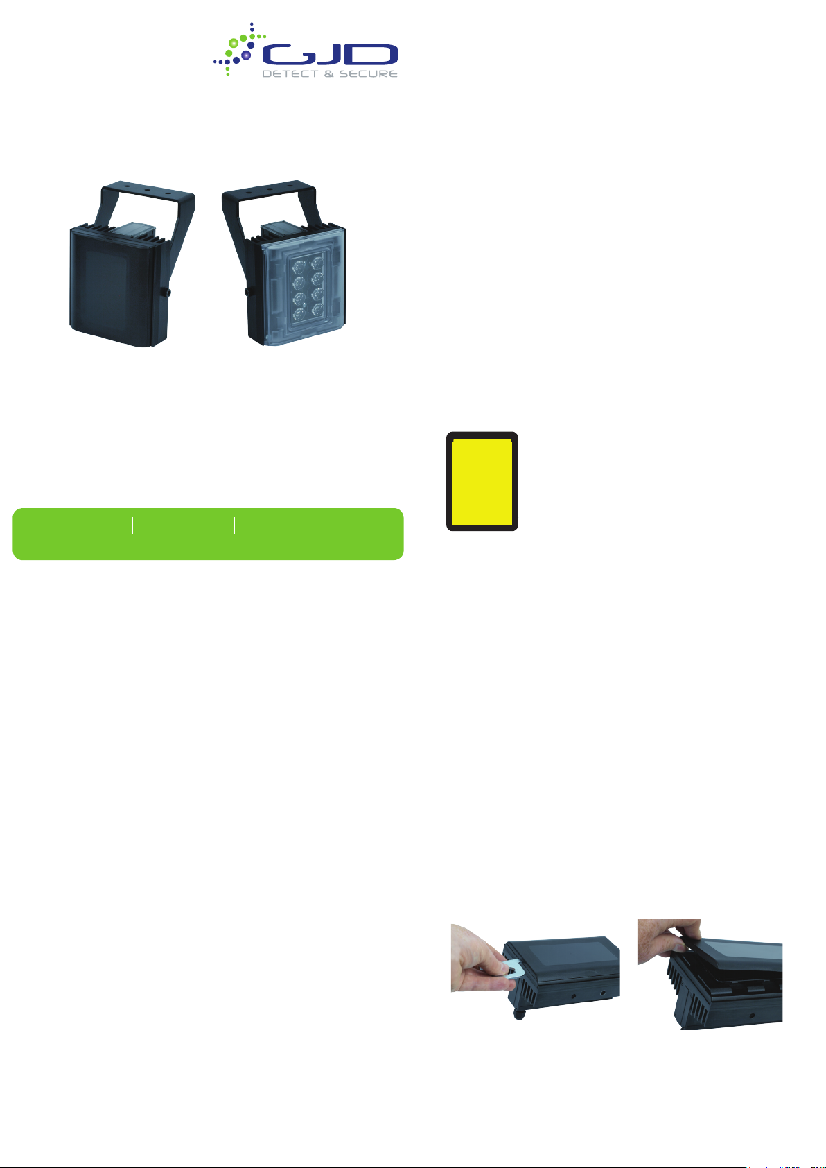
Description
A complete range in infra-red and white light illuminators for
CCTV, the visible and Invisible range feature state of the art
technology and installation friendly design.
• Energy efcient, low voltage operation for quick and easy
installation
• Dual Core LED™ technology with advanced electronic
control circuitry deliver improved thermal management,
long life and low cost of ownership.
• CleanLITE® Self Cleaning Lens Coating Technology
• Semi covert, covert and visible white light versions.
• Built in photo cell
• Easy integration with day/night cameras with relay contacts
indicating if the built in photo cell has activated the
illuminator
• Remote telemetry input
• Easy access to power and photo cell adjust
• Pressure equalisation vent prevents thermal expansion and
pressure cycling
• Interchangeable Lens Diffuse Technology
• Dual Core® Technology
• Interchangeable Lens Diffuser Technology
www.gjd.co.uk info@gjd.co.uk +44 (0) 1706 363 998
Unit 2 Birch Business Park, Whittle Lane, Heywood, Lancashire, OL10 2SX
Specification
Electronics High efciency surface mount high
power LEDs with advanced current
limited integral control circuitry
Beam Angles 10º circular, 20º, 30º, 60º, 80º and 95º elliptical
Lens/Beam Pattern The illuminator should be matched to
the scene and the camera lens focal
length
Wavelength 850nm, 940nm and visible white light
Expected Life 10 years
Consumption Clarius IS / Clarius VS 15W
Clarius IM / Clarius VM 26W
Clarius IL / Clarius VL 39W
Clarius IX / Clarius VX 52W
Input Voltage 12-32V DC or 24V AC 50-60 Hz
Operating Temp -50° to 50° (-58° to 122°F)
Environmental IP66. Suitable for indoor and outdoor use
Construction Robust high quality aluminium
extrusion
Front Window Polycarbonate high transmittance
protection (vandal-proof) with
CleanLITE® technology
Dimensions Clarius IS+ / Clarius VS 68 x 110 x 78mm
Clarius IM / Clarius VM 114 x 110 x 78mm
Clarius IL / Clarius VL 161 x 110 x 78mm
Clarius IX / Clarius VX 213 x 110 x 78mm
Weight Clarius IS / Clarius VS 750g (1.6lbs)
Clarius IM / Clarius VM 1.05kg (2.3lbs)
Clarius IL / Clarius VL 1.35kg (3lbs)
Clarius IL / Clarius VL 1.75kg (3.9lbs)
Power Cable 3m (9ft). Other lengths available to order
Mount Black power coated stainless steel wall
mount. Adjustable via M6 Allen Key
(included)
RISK
GROUP 2
CAUTION
IR emitted
from this
product
Installation
Note:
• Installation should be done by skilled personnel or under supervision
of such personnel
• The illuminator is low voltage 12-32V DC or 24V AC.
• Only to be installed in restricted Access Areas.
• Terminal block not included. Installation may require advice from a
qualied person.
Optimum results are achieved by setting up at night and viewing the
results on a monitor.
1. Attach the illuminator mount to pan/tilt unit, wall or camera housing.
Using stainless steel xings suitable for the relevant application.
2. Connect the lamp to a suitable (SELV) low voltage supply. Ensure
that the polarity is correct.
3. Commission the mains supply, camera and monitoring equipment.
4. Select the diffuser angle sheet required from the Clarius box (if
required). To position the required diffuser sheet, insert the tool
included in the slot at the bottom of the cover and prise upwards
slowly. Repeat at opposite end and carefully remove cover.
Remove backing sheet from the two adhesive discs and secure
required diffuser in position. Finally rmly clip the lens cover back into
place.
5. Adjust the pan angle of the illuminator to match the camera eld of
view.
6. Adjust the vertical alignment by loosening the side bolts (one on
each side of the main body) to maximise the results.
7. Tilt the lamp downwards until the rear part if the required eld of
view is saturated with light, as viewed on the monitor.
8. SLOWLY and GRADUALLY tilt the lamp upwards until the for part of
the required eld of view is illuminated correctly on the monitor.
Page 2
Power and Control Cable Connections
Camera
White. Volt Free / Night Switching (N/O)
Yellow. Volt Free/ Night Switching (COM)
(60V, 0.2A)
Green Telemetry Blue Telemetry +
External circuits used for interfacing with the illuminator (Camera Day/Night
switching and Telemetry) should be reinforced/double insulated from mains.
MAINS
INPUT
Day/Night switching
SELV
PSU
Power Adjust
To adjust the power, rst unscrew the sealing cap then adjust the power
potentiometer clockwise to increase the power and counter clockwise to turn it
down. The unit is factory set to maximum output.
Photocell
The photocell is designed to automatically switch the lamps on at dusk and turn
off at dawn. A high degree of hysteresis is incorporated to void on/off switching in
marginal conditions. The unit is factory set at approximately 30 Lux On and 70 Lux
Off, but can be adjusted.
Photocell Sensitivity
To adjust the photocell sensitivity rst remove the sealing cap, then adjust the
potentiometer to turn the lamp on when lighting conditions are lighter or darker.
Adjust the counter clockwise to make the lamp turn on when it is lighted and
clockwise when it’s darker.
Use suitable IP66 rated enclosure and terminal block for connection
conforming to EN60998-2-1 or EN60998-2-2
Recommended PSU
IS / IM , VS/VM : 24V 30W (ALT-30-24)
IL / IX , VL/VX : 24V 60W (ALT-60-24)
Use only with Class 2 power supply.
SELV Power supply should be approved to relevant EN Safety standards.
SELV Power Supply should be used with devices to protect against short
circuits and overload.
Remote Switching
The Illuminator may be activated remotely by a volt-free contact latched across
the telemetry wires (see Diagram above).
Photocell following contact
Volt-free relay contact-normally open (day) to normally closed (night). See
Diagram above.
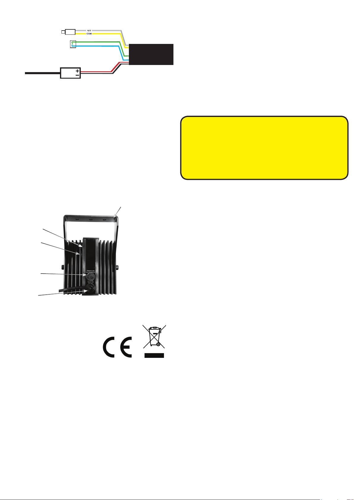
Pot for photocell
adjustment
Pot for power
adjustment
Pressure relief
valve
mount
Disabling the photocell
To disable the photocell, adjust the sensitivity fully counter clockwise. This will make
the lamp turn on at all times.
Safety Warning
• When the lamp is running, it is hot to touch. before touching switch off
the illuminator and allow to cool for a minimum of 10 minutes.
• The illuminator should be positioned so that prolonged starring into the
illuminator at a distance closed than 1m is not expected.
• The light source of this illuminator is not replaceable, when the light
source reaches its end of life the whole illuminator should be replaced.
• If the exible power cord of the illuminator is damaged it should be
exclusively replaced by an authorised service agent.
• This equipment is not suitable for us in locations where children are likely
to be present.
PoE Models
The Clarius PoE/PoE+ series illuminators are powered by Power over the Ethernet
(PoE) via a network cable connector to a PoE IEEE802af/IEEE802at compliant
switch.
The power consumption of the illuminators comply with PoE IEEE802af and
IEEE802at.
These illuminators are not supplied with a power cord. Instead, they are supplied
with a 2.5m (8’) long network cable. At the end of the network cable is a female
RJ45 Cat5e compliant connector with an IP68 rated cover.
The IP68 rated cover is supplied with the illuminator. Follow the instructions supplied
with the cover on how to attached if to the male Cat5e network cable.
ENSURE THAT THE IP68 RATED COVER IS CORRECTLY FITTED AND ATTACHED TO THE
NETWORK CABLE. IF THIS IS NOT FITTED CORRECTLY MOISTURE CAN GET INTO THE
CONNECTOR AND MAY CAUSE THE UNIT TO MALFUNCTION. THIS WOULD VOID THE
WARRANTY ON THE PRODUCT.
Power and
control cable
Certifications
This product complies with the European Directive 2014/30/EU
Electromagnetic Compatibility and 2014/35/EU Low Voltage Directive by
meeting the following standards:
CE-EMC EN 61547 (Lighting-Immunity)
EN 55015 (Lighting-Emission)
EN 62493 (Lighting -EMF)
EN 50130-4 (Alarm-EMC)
CE-LVD EN 60598-1 (Luminaires-General)
EN 60598-2-1 (Luminaires)
Safety EN 62471 Risk group 2 (LED safety)
Environmental IEC/EN 60529 IP66
EN50130-5 (Alarm-environmental)
USA FCC, Class B
AUS RCM (AS/NZS CISPR 22 Class B)
WEEE: Waste Electrical & Electronic Equipment European
directive 202/96/EC
RoHS: Restriction of Hazardous Substances European
directive 202/95/EC
This symbol on the product means that the electrical and/or electronic
equipment to which it relates should be disposed of at the end of life
separately from domestic household waste.
There are separate collection systems for recycling in the EU. For more
information please contact the Local Authority or supplier of the product.
Trouble Shooting
Ensure all tests are undertaken by a qualied, trained engineer and
ensure safe working practices are followed at all times.
Step 1: Basics
• Check power connection
• Ensure power is 12-32V DC / 24V AC 50-60Hz
• Check the photocell is working - cover photocell ,light should turn
on
• Ensure power supply is suitably rated to product - check the
specications
Step 2: Lamp Test
• Check current draw of lamp corresponds to specication
• Check current of lamp - see instructions for correct current settings
To check lamp current remove +ve (red) lead from power supply and
connect a multimetre (set to 10A) in line with the lamp. (One lead of
multimeter in common (COM) other lead into 10A socket of multimeter;
set multimeter to read Amps). Refer to PSI Specications for correct
current settings.
Step 3: Set up Camera, lens and Illumination
• Check alignment of lamp
• Check camera lens- fully open at night and set correctly
• Check model number to performance specication to ensure
required distance is achievable
Step 4: Call for further assistance
If the lamp is still not delivering the required performance, please
contact Technical Support for further assistance
Note down:
• Model number and serial number of illuminator
• Camera make and model
• Lens make and model
 Loading...