

Gizmow Formula, Formula F2761KH-EU Operator's Manual

Operator’s Manual

Introduction
Formula - 20071
i
CONGRATULATIONS on the purchase of your Gizmow Mower. This
product has been carefully designed, tested and manufactured to give you
a maximum amount of dependability and years of trouble-free operation. If
any additional information is needed contact your authorised Gizmow dealer
or distributor. If you need to order parts, please give them the model
number and serial number as well as the part number and quantities
needed.
MODEL NUMBER _______________________
SERIAL NUMBER _______________________
Engine Serial Number___________________

Introduction
Formula - 20071
1
OPERATOR'S MANUAL
This manual contains assembly, operating, maintenance, adjustment, and safety
instructions for your Gizmow mower.
BEFORE OPERATING YOUR MOWER, CAREFULLY READ THIS MANUAL IN ITS ENTY.
By following the operating, maintenance, and safety instructions, you will prolong the life
of your mower, maintain its maximum efficiency, and promote safe operation and
maintenance.
If additional information is needed, or should you require trained mechanic service,
contact your authorized Gizmow equipment dealer or distributor.
All Gizmow equipment dealers and distributors are kept informed of the latest methods of
servicing and are equipped to provide prompt and efficient service in the field or at their
service stations. They carry ample stock of service parts or can secure them promptly for
you from the factory.
All Gizmow parts are thoroughly tested and inspected before leaving the factory, however,
attention is required on your part if you are to obtain the fullest measure of satisfaction
and performance from your mower.
Parts Quick Reference
Part Number Description Quantity
H18218 Blade - Right-hand 2
H18219 Blade - Left-hand 1
H15228 Bolt - Blade 2
H15241 Bolt - Blade - R.H. spindle 1
H15229 Washer - Blade bolt 3
H18177 Spindle - Assembly - Left and centre 2
H18055 Spindle - Assembly - Right hand side 1
H18191 Belt - Deck drive belt 1
H18228 Belt - Right-hand blade 1
H18227 Belt - Gearbox 1
H18100 Belt - Hydro 1
H18035 Wheel - Anti-scalp 4
H13145 Wheel - Caster 2
H18031 Relay 8
H18118 Filter - Hydro 1
2405002 Filter- Fuel 1
2508301-S Filter - Air primary 1
2508304-S Filter - Air safety 1

Formula - 20071
2
EC DECLARATION OF CONFORMITY
DECLARATION CE DE CONFORMITE
EG-KONFORMITATSERKLARUNG
______________________________________________________________
Manufacturer's Name: Gizmow Inc
Manufacturer's Address: 2072 McDonald Avenue,
New Albany
Indiana USA
47151-1027
Declares that this product: Gizmow Formula - F2761KH-EU
Description of Equipment: Lawnmower
This machine complies with the essential health & safety requirements relating to
design and construction of machinery in accordance with EC directive 98/37/EC
and conforms to the outdoor noise directive 200/14/EC-ANNEX VI Procedure 2 –
and also complies with electromagnetic compatibility according to EC directive
89/336/CEE.
Measured Sound Power Level: 104 dB L
wa
Guaranteed Sound Power Level: 105 dB L
wa
Mower Cutting Width: 1.55m
Contact Details for Manufacturers: Gizmow (Europe) Limited
Regent House,
Whitewalls Industrial Estate
Colne, Lancashire, BB8 8LJ
United Kingdom
Tel: +44 (0) 1282 856828
Fax: +44 (0) 1282 860555
Notified Body : AV Technology Limited
Birdhall La ne,Cheadle Heath
Stockport, Cheshire SK3 0XX
United Kingdom
Place of Declaration: Regent House
Whitewalls Industrial Estate
Colne, Lancashire, BB8 8LJ
United Kingdom
Signed
Christopher R Gibson
C R Gibson
Director
Date: 10
th
November 2006

Introduction
Formula - 20071
3
TABLE OF CONTENTS
SAFETY Page 4
SPECIFICATIONS Page 13
ASSEMBLY INSTRUCTIONS Page 17
OPERATION INSTRUCTIONS Page 19
MAINTENANCE & ADJUSTMENTS Page 27
WASTE DISPOSAL Page 47
TROUBLE SHOOTING Page 49
ELECTRICAL DIAGRAMS Page 50
HYDRAULIC DIAGRAM Page 51
WARRANTY Page 52

Introduction
Formula - 20071
4
1. SAFETY
1.1 SAFETY ALERT SYMBOL
This SAFETY ALERT SYMBOL is used both in this manual and on the machine to identify
important safety messages, which must be followed to avoid accidents. This symbol
means:
ATTENTION! BECOME ALERT!
YOUR SAFETY IS INVOLVED!
The safety alert symbol appears above information, which alerts you to unsafe actions or
situations and will be followed by the word
DANGER, WARNING, or
CAUTION.
DANGER: White lettering / Red background. Indicates an imminently hazardous
situation, which, if not avoided, WILL result in death or serious injury.
WARNING: Black lettering / Orange background. Indicates a potentially
hazardous situation, which, if not avoided, COULD result in death or serious
injury.
CAUTION: Black lettering / Yellow background. Indicates a potentially
hazardous situation, which, if not avoided, MAY result in minor or moderate
injury.
1.2 TRAINING
1.2.1 Regard the Gizmow mower as a piece of power equipment and teach this to all
who operate this unit.
1.2.2 Read the instructions carefully. Familiarize yourself with the controls and the
proper use of the equipment. If the operator(s) or mechanic(s) can not read English it is
the owners responsibility to explain this material to them.
1.2.3 Do not allow operation of this machine by untrained personnel. Never allow
children, teenagers, or people unfamiliar with these instructions to use the mower. Local
regulations may restrict the age of the operator.
1.2.4 Avoid mowing while peop le, especially children, or pets, are nearby. Keep in mind
that the operator or user is responsible for accidents or hazards occurring to other people
or their property.
1.3 PREPARATION
1.3.1 Evaluate the terrain to determine what accessories and attachments are needed
to properly and safely perform the job. Only use accessories and attachments approved
by Gizmow Inc.
1.3.2 The use of personal protective equipment, such as (but not limited to) protection
for the eyes, ears, feet, and head is recommended.
POTENTIAL HAZARD
This machine produces sound levels in excess of 85 dBA at the operators ear when in
operation.
CAUTION
CAUTION

Introduction
Formula - 20071
5
WHAT CAN HAPPEN
Exposure to sound levels of 85 dBA or above for extended periods of time can cause
hearing loss.
HOW TO AVOID THE HAZARD
Wear hearing protection when operating this machine.
1.3.3 While mowing, always wear substantial footwear and long trousers. Do not
operate equipment when barefoot or when wearing open sandals.
1.3.4 Thoroughly inspect the area where the equipment is to be used and remove all
stones, sticks, wires, bones, and other foreign objects which may dam age the equipment
or cause personal injury to the operator or bystanders.
POTENTIAL HAZARD
Engine exhaust contains carbon monoxide, which is an odourless deadly poison.
WHAT CAN HAPPEN
Carbon monoxide can kill you.
HOW TO AVOID THE HAZARD
Do not run engine indoors or in a small confined area where dangerous carbon
monoxide fumes can collect.
POTENTIAL HAZARD
In certain conditions gasoline is extremely flammable and highly explosive.
WHAT CAN HAPPEN
A fire or explosion from gasoline can burn you, others, and cause property damage.
HOW TO AVOID THE HAZARD
DO NOT smoke while refuelling, and stay away from an open flame or where gasoline
fumes may be ignited by spark.
Refuel only outdoors.
Store gasoline in an approved container and keep it out of the reach of children.
Add fuel before starting the engine. Never remove the cap of the fuel tank or add fuel
when engine is running or when the engine is hot.
Never fill the fuel tank so that the gasoline level rises above a level that is 1/2 below
the bottom of the filler neck to allow for gasoline expansion and prevent fuel spillage.
If fuel is spilled, DO NOT attempt to start the engine. Mo ve away from the area of the
spill and avoid creating any source of ignition until fuel vapours have dissipated.
Do not operate without en exhaust system in place and in proper working condition.
DANGER
DANGER
DANGER
DANGER
DANGER
DANGER

Introduction
Formula - 20071
6
POTENTIAL HAZARD
In certain conditions gasoline is extremely flammable and highly explosive.
WHAT CAN HAPPEN
A static charge can ignite gasoline vapours. A fire or explosion from gasoline can burn
you, others, and cause property damage.
HOW TO AVOID THE HAZARD
Purchase and store gasoline only in an approved container.
Always place gasoline containers on the ground away from your vehicle be fore filling.
Do not fill gasoline containers inside a vehicle or on a truck or trailer bed because
interior carpets or plastic truck bed liners may insulate the container and slow the
loss of any static charge.
When practical, remove gas-powered equipment from the truck or trailer and refuel
the equipment with its wheels on the ground.
If this is not possible, then refuel such equipment on a truck or tr ailer fr om a portable
container, rather than from a gasoline dispenser nozzle.
If a gasoline dispenser nozzle must be used, keep the nozzle in contact with the rim
of the fuel tank or container opening at all times until fueling is complete.
POTENTIAL HAZARD
Gasoline vapour can collect inside enclosed trailers and may be ignited by electrical
sparks or hot engine/exhaust components.
WHAT CAN HAPPEN
Explosion and fire may occur, resulting in property damage, personal injury, and/or
death.
HOW TO AVOID THE HAZARD
Provide adequate ventilation of any enclosed trailer to prevent build up of gasoline
vapours, especially at floor level.
Refuel only outdoors, never inside an enclosed trailer.
Be sure all fuel tanks and gasoline storage containers have proper caps installed to
prevent spillage and minimize vapour escaping into the trailer.
Do not place any equipment that is leaking gasoline in an enclosed trailer.
1.4 OPERATION
Although hazard control and accident prevention are partially dependent upon the design
and configuration of the equipment, these factors are also dependent upon the
awareness, concern, prudence, and proper training of all of the personnel involved in the
operation, transport, maintenance, and storage of the equipment. It is essential that all
Operator Safety Mechanisms be connected and in operating condition prior to use for
mowing or transporting the machine.
DANGER
DANGER

Introduction
Formula - 20071
7
POTENTIAL HAZARD
Operating engine parts, especially the muffler, become extremely hot.
WHAT CAN HAPPEN
Severe burns can occur on contact.
Debris, such as leaves, grass, brush, etc. can catch fire.
HOW TO AVOID THE HAZARD
Allow engine parts, especially the muffler, to cool before touching.
Remove accumulated debris from muffler and engine area.
Install and maintain in working order a spark arrester before using equipment on
forest-covered, grass-covered, or brush-covered land.
POTENTIAL HAZARD
Hands, feet, hair, clothing, or accessories can become entangled in rotating parts.
WHAT CAN HAPPEN
Contact with rotating parts can cause traumatic amputa ti on or s e vere lacerations.
HOW TO AVOID THE HAZARD
Do not operate the machine without guards, shields, and safety devices in place and
working properly.
Keep hands, feet, hair, jewellery, or clothing away from rotating parts.
1.4.1 Give complete, undivided attention to the job at hand.
1.4.2 Mow only in daylight or good artificial light, keeping away from holes and hidden
hazards. NEVER carry passengers.
DO NOT operate the mower when children or others are in the area!
1.4.3 When feasible, avoid operating the equipment in wet grass.
1.4.4 Use EXTREME caution when mowing and/or turning on slopes as loss of traction
and/or tip-over could occur. The operator is responsible for safe operation on slopes.
POTENTIAL HAZARD
Mowing on wet grass or steep slopes can cause sliding and loss of control.
WHAT CAN HAPPEN
Wheels dropping over edges, ditches, steep banks, or water can cause roll-overs,
which may result in serious injury, death or drowning.
DANGER
DANGER
WARNING
WARNING
DANGER
DANGER

Introduction
Formula - 20071
8
HOW TO AVOID THE HAZARD
Do not mow slopes when grass is wet.
Do not mow near cliff edges or near water.
Do not mow slopes greater than 15 degrees.
Reduce speed and use extreme caution on slopes.
Avoid sudden turns or rapid speed changes.
Use a walk behind mower and/or a hand trimmer near cliff edges, ditches, steep
banks or water. These areas can be dangerous. Always mow across the slope not up
and down a slope. Mow across an incline and never mow an incline that is too steep
for balance and control.
Progressively greater care is needed as the slope increases.
Always avoid sudden starting or stopping on a slope. If tyres lose traction, disengage
the blades and proceed slowly off the slope.
Avoid sudden starts when mowing uphill. Mower may tip backwards.
Be aware that loss of traction may occur going downhill. Weight transfer to the front
wheels may cause drive wheels to slip and cause loss of braking and steering.
Watch for ditches, holes, rocks, dips, and rises that change the operating angle, as
rough terrain could overturn the machine.
Remove or mark obstacles such as rocks, tree limbs, etc. from the mowing area. Tall
grass can and does hide obstacles.
Use extreme care with grass catchers or attachments. These will change the stability
of the machine and can cause loss of control.
Follow the manufacturers recommendations for wheel weights or counterweights to
improve stability.
1.4.5 Use EXTREME caution when backing up. LOOK BEHIND YOU!
1.4.6 Stop the blades when crossing surfaces other than grass and when transporting
the mower to and from the area to be mowed.
1.4.7 Never operate the mower with defective guards, shields, or covers. Always have
safety shields, guards, switches, and other devices in place and in proper working
condition.
1.4.8 DO NOT change the engine gov ernor settings or o verspeed the engine. Operating
an engine at excessive speed may increase the hazard of personal injury.
1.4.9 Disengage PTO before starting engine.
1.4.10 Start the engine carefully with feet well away from the blades.
1.4.11 Keep hands, feet, and clothing away from rotating parts while the mower is being
operated.
1.4.12 Stop engine, wait for all moving parts to stop, and remove key:
• Before checking, cleaning or working on the mower.
• After striking a foreign object (inspect the mower for damage and make repairs
before restarting and operating the mower).
• Before clearing blockages.
• Whenever you leave the mower.
• Stop the engine and wait for all moving parts to stop:
• Before refuelling.

Introduction
Formula - 20071
9
• Before dumping the grass catcher.
1.4.13 Before stopping the engine, place the throttle control midway between the slow
and fast positions. Allow the engine to run a minimum of 15 seconds; then stop the
engine.
1.4.14 The fuel system is provided with a shut-off valve. The fuel shut-off valve is used
to shut off the fuel:
• When the machine will not be used for a few days.
• During transport on the trailer, to and from the job site.
• Whenever parked inside a building.
1.4.15 This mower was designed for use by one operator only. Keep all others away from
mower during operation.
1.4.16 Do Not mow with the discharge deflector raised, removed, or altered unless
there is a grass collection system or mulch kit in place and working properly.
1.4.17 Be aware of the mower discharge and direct discharge away from others.
1.4.18 Do Not operate the mower under the influence of alcohol or drugs.
1.4.19 Use extra care when approaching blind corners, shrubs, trees, or other objects
that may obscure vision.
1.4.20 If jump starting is required:
a. Connect the positive (+) power cable from the positive post on the booster
battery to the positive terminal post on the starter solenoid switch (this post
has the positive battery cable attached to it).
b. Connect the negative or ground cable (-) from the negative post on the
booster battery to any engine deck ground, preferably the engine block as far
away from the battery as possible.
c. Start the machine.
d. Disconnect battery cables in the reverse order after starting.
1.1 MAINTENANCE AND STORAGE
1.1.1 For engine maintenance, follow the engine manufacturers recommendations
precisely as stated in the engine manual.
1.1.2 Disconnect the battery cable from the negative battery post when the unit will be
allowed to sit for more than 30 days without use.
1.1.3 Allowing batteries to stand for an extended period of time without recharging
them will result in reduced performance and service life. To preserve optimum battery
performance and life, recharge batteries in storage when the open circuit voltage drops to
12.4 volts. Note: To prevent damage due to freezing, battery should be fully charged
before putting away for winter storage.
1.1.4 Keep engine, engine area, and hydraulic pump area free from accumulation of
grass, leaves, excessive grease or oil, and other debris which can accumulate in these
areas. These materials can become combustible and may result in a fire.
1.1.5 Store fuel in a container specifically designed for this purpose in a cool, dry place.
1.1.6 Keep the mower and fuel container in locked storage to prevent children from
playing or tampering with them.
1.1.7 Gasoline powered equipment or fuel containers should not be stored in a
basement or any enclosed area where open pilot lights or heat appliances are present.
1.1.8 Maximum mowing results and safety can only be achieved if the mower is

Introduction
Formula - 20071
10
properly maintained and operated correc tl y.
1.1.9 Check all bolts frequently to maintain proper tightness.
1.1.10 Keep all guards, shields and all safety devices in place and in safe working
condition.
1.1.11 Frequently check for worn or deteriorating components that could create a
hazard.
1.1.12 All replacement parts must be the same as or equivalent to the parts supplied as
original equipment.
POTENTIAL HAZARD
Hydraulic fluid escaping under pressure can penetrate skin and cause injury.
WHAT CAN HAPPEN
Fluid accidentally injected into the skin must be surgically remov ed within a few hours
by a doctor familiar with this form of injury or gangrene may result.
HOW TO AVOID THE HAZARD
Make sure all hydraulic fluid hoses and lines are in good condition an all hydraulic
connections and fittings are tight before applying pressure to hydraulic system.
Keep body and hands away from pinhole leaks or nozzles that eject high pressure
hydraulic fluid.
Use cardboard or paper, not your hands, to find hydraulic leaks.
Safely relieve all pressure in the hydraulic system by placing the control pedals in
neutral and shutting off the engine before performing any work on the hydraulic
system.
1.2 SAFETY SIGNS
1.2.1 Keep al l safety signs legible. R emo ve all grease, dirt, and debris from safet y signs
and instructional labe ls .
1.2.2 Safety signs must be replaced if they are missing or illegible.
1.2.3 When new components are installed, be sure that current safety signs are affixed
to the replaced components.
1.2.4 New safety signs may be obtained from your authorised Gizmow Inc. equipment
dealer or distributor or from Gizmow Inc.
1.2.5 Safety signs may be affixed by peeling off the backing to expose the adhesive
surface. Apply only to a clean, dry surface. Smooth to remove any air bubbles.
1.2.6 Familiarize yourself with the following safety signs and instruction labels. They
are critical to the safe operation of your Gizmow commercial mower.
WARNING
WARNING
Introduction
Formula - 20071
11
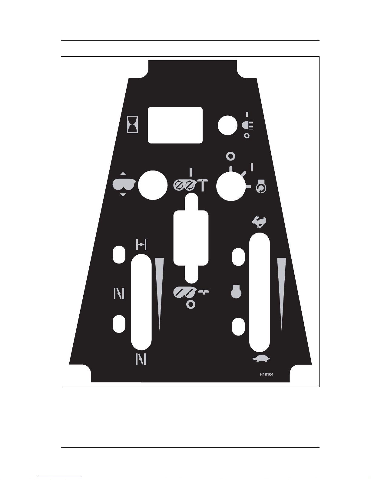
H18104 Control Panel Decal
Introduction
Formula - 20071
12
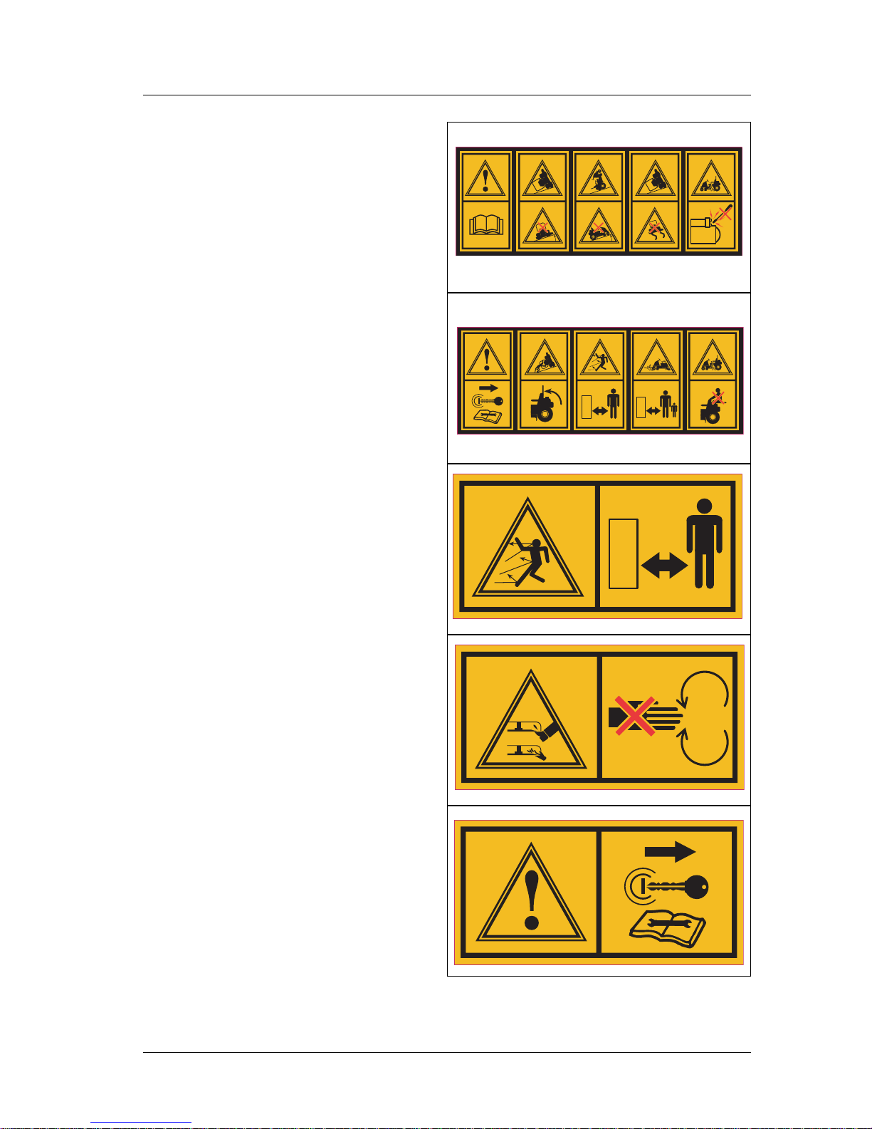
H18235 Warning decal – located on rear
footstep plate and on plate on right-hand
side of seat.
H18236 Warning decal – located on rear
footstep plate and on plate on right-hand
side of seat.
H18237 Warning decal - Danger of thrown
objects. Keep bystanders at a safe distance.
Located on both sides of mower deck.
H18238 Warning decal - Rotating blades.
Keep feet and hands away from mower
deck. Located on both sides of mower deck.
H18239 Warning decal - Do not perform
any maintenance work before reading and
understanding the contents of the Operator
Instruction Book. Located on both sides of
mower deck.
18ß18ß

Specifications
Formula - 20071
13
2. SPECIFICATIONS
2.1 MODEL NUMBER: F6127KH
2.2 ENGINE: Kohler 27 Horizontal shaft
2.2.1 Engine Specifications: See Your Engine Owners Manual
2.2.2 RPM: Full Speed: 3100 RPM (No Load) Idle: 1500 RPM
2.3 FUEL SYSTEM
2.3.1 Capacity: 9.75 gal. (37 litres)
2.3.2 Type of Fuel: Regular unleaded gasoline, 87 octane or higher.
2.3.3 Fuel Filter: For Kohler: Replaceable in-line 15 Micron Kohler P/N 2405002
2.3.4 Fuel Shut-Off Valve: 1/4-turn increments (left-hand tank, OFF, right-hand tank)
2.4 ELECTRICAL SYSTEM
2.4.1 Charging System: Flywheel Alternator
2.4.2 Charging Capacity: 15 amps
2.4.3 Battery Type: BCI Group U1
2.4.4 Battery Voltage: 12 Volt
2.4.5 Polarity: Negative Ground
2.4.6 Fuses: Two 20-amp blade type
2.4.7 Safety Interlock System: PTO must be disengaged, brake engaged, and foot
pedals in neutral position (neutral lock) to start engine. Operator must be in seat
when PTO is engaged, brake is disengaged or engine will stop. To proceed forward
the brake must be disengaged or the interlock system will stop the engine.
2.5 OPERATOR CONTROLS
2.5.1 Steering and Motion Control:
Steering wheel controls the direction the mower moves including going into zero turn.
Two separate foot pedals control the direction and speed of travel. The one on the left-
hand side of the operator is reverse marked
È and controls the reverse speed. The
further the pedal is depressed t he faster the mower will move in a reverse direction. The
pedal on the right-hand side of the operator position is for forward travel as well as zero
turns. It is marked as
Ç. The further the forward pedal is depressed the faster the mower
will move in a forward direction.
2.5.2 PTO Switch: Engages electric clutch (to drive belt) which engages mower blades.
2.5.3 Parking Brake Lever: Engages parking brake.
2.5.4 Deck Height Toggle switch: Sets cutting height to desired position.
2.5.5 Horn – located on the side of the control panel is a horn button – depress to
sound the horn. This will only work when the key is in the ‘ON’ position.

Specifications
Formula - 20071
14
2.6 SEAT
2.6.1 Type: Standard seat: high back, foam padded (internal spring suspension).
2.6.2 Mounting: Seat is hinged to tilt up for access to hydraulic pumps, control cables
and other components. This can be held in tilted position with the prop rod. Adjustable
fore and aft seat track. Seat is also adjustable in position on the seat plate. 3 sets of hole
positions are provided.
2.6.3 Armrests: Padded flip-up ar mrests with height adjustment.
2.6.4 Seat Safety Switch: Incorporated into the safety inte rl ock system.
2.7 HYDROSTATIC GROUND DRIVE SYSTEM
2.7.1 Hydrostatic Pumps: Two Hydro Gear 12cc variable displacement piston pumps.
2.7.2 Wheel Motors: Two Danfoss wheel drive motors with 1 1/4” tapered shafts.
2.7.3 Hydraulic Oil Type: Synthetic Mobil 1 15W-50.
2.7.4 Hydraulic Oil Capacity: 2.84 litres.
2.7.5 Hydraulic Filter: Replaceable cartridge type - P/N H18118: 10 micron
2.7.6 Speeds: 0 to 10.0 m.p.h. (16 kph) forward, 0 to 5.0 m.p.h. (5 kph) reverse.
2.7.7 Drive wheel release valves (located on the hydraulic pumps) allow machine to be
moved when the engine is not running.
2.8 TYRES AND WHEELS
2.8.1 Tyres: Size Qty Tread Ply Inflation
Drive Tyres 24-12-12 2 AT101 4 16 psi
Front Tyres 13-500-6 2 Smooth 4 16 psi
2.9 CUTTING DECK
2.9.1 Cutting Width:
61” DECK – 61”
2.9.2 Discharge: Rear or mulch.
2.9.3 Blade Size:
61” deck – (3) 21” blades
2.9.4 Blade Spindles: cast aluminum spindle with 1” I.D. bearings.
2.9.5 Deck Drive: Electric clutch mounted on horizontal engine shaft. Blades are driven
by two B section belts (w/self-tensioning idler) direct from the engine.
2.9.6 Deck: Full floating deck is attached to main frame. Deck design allows for
mulching or rear discharge.
2.9.7 Cutting Height Adjustment: an electric actuator controlled by a toggle switch on
the console is used to adjust the cutting height anywhere from 1” to 5”. The position is
shown on an indicator located to the operators right above the rear of the deck. All
adjustments can be made while the operator remains seated. The cutting height may be
increased and additional ¾ of inch upwards (for a max cut height of 5 ¾” by moving the
three ¼” spacers between the blade and the spindle to above the spindle.
2.9.8 Mulching Kit: Optional.

Specifications
Formula - 20071
15
2.10 DIMENSIONS
2.10.1 Overall Width:
w/61” Deck 63 ¼” (161 cm)
2.10.2 Overall Length: 80” (203 cm)
2.10.3 Overall Height: 47” (119 cm)
2.10.4 Tread Width: (centre to centre of tyres)
Drive Wheels ............. 41 ½” (105 cm)
Front Casters............. 33 ½” (85 cm)
2.10.5 Wheel Base: 50 ¼” (128 cm)
2.10.6 Weight:
w/61” Deck ............... 1190 lbs (539 kg)
2.11 TORQUE REQUIREMENTS
Bolt Location Torque
Cutter Housing Spindle Nut....................................... 70-80 ft-lbs.
Blade Mounting Bolt................................................. 70-80 ft-lbs.
Engine Deck/Front Frame Mount Bolts ........................ 30-35 ft-lbs.
Anti-Scalp Roller Bolts..............................................40-45 ft-lbs.
Engine Mounting Bolts.............................................. 25-30 ft-lbs.
Wheel Motor Mounting Bolts......................................72-77 ft-lbs.
Wheel Hub Slotted Nut.............................................minimum 150 ft-lbs.
Wheel Lug Nuts............................... ........................ 90-95 ft-lbs.
 Loading...