

Page 1
INTRINSICALLY SAFE ALARM IS-AB
1.
CONNECT BATTERY
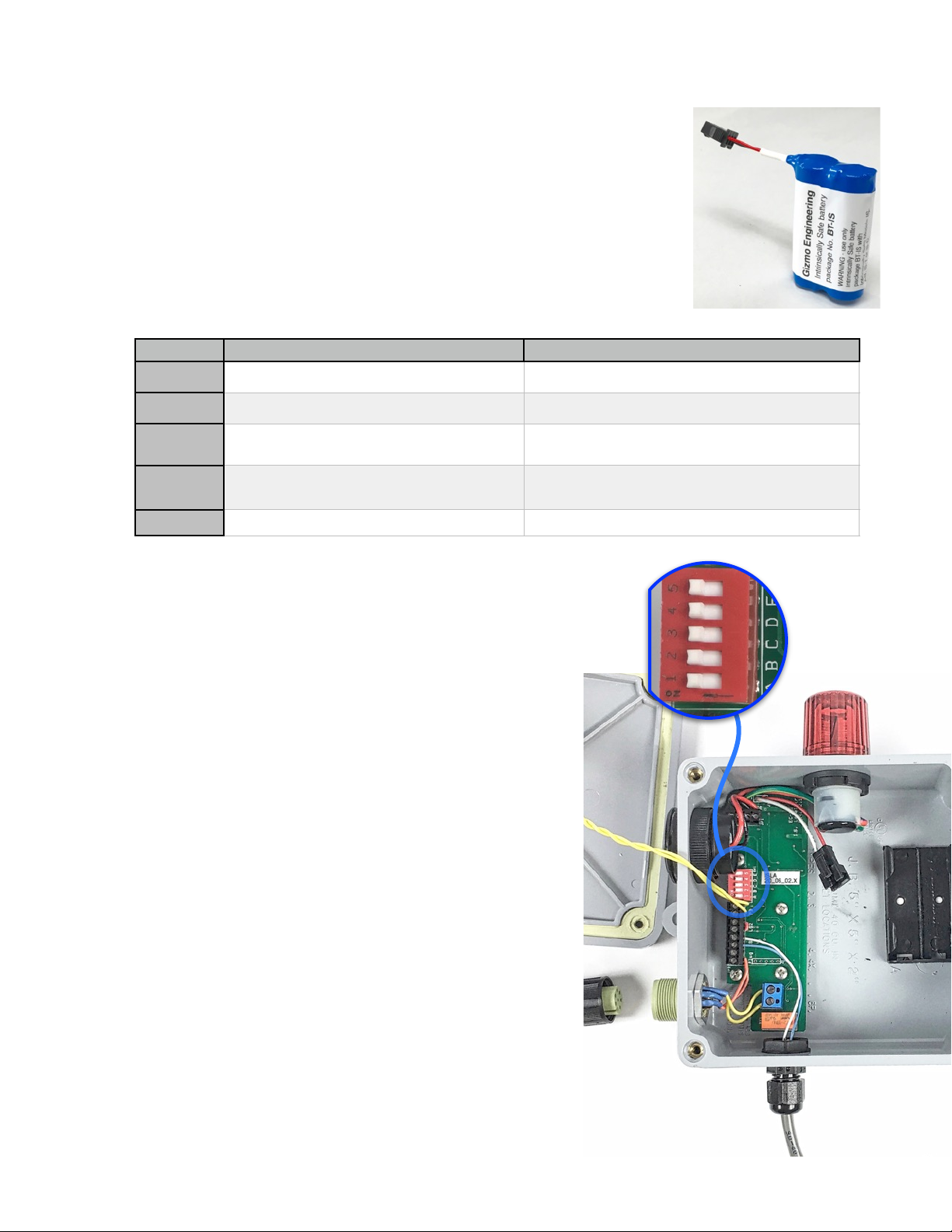
The battery pack connects with the JST connector. Only battery model
BT-IS may be used. Battery is Intrinsically Safe and may be changed
in the hazardous area. Refer to control drawing IS-001.
2.
PROGRAM DESIRED MODE
•
The modes available are selected using the DIP switches as follows:
3.
OPERATION
•
When there is a level alarm, the LED and buzzer will alternate. The front
button silences the buzzer. In the mode with switch #2 “ON”, the LED
will continue to flash until level is corrected. If switch #1 is “ON” the
buzzer will sound again after a 30 minute “snooze”.
•
If the alarm is not acknowledged for 60 minutes, the alarm output
will be reduced to save battery power. After 60 minutes, all alarms
will be reduced to only 5 sec. every 30 seconds. This allows the
alarm to last for up to 600 hours (25 days) in this power-saving
mode.
4.
OTHER POINTS
•
Operating temperature is -40ºC to 60ºC. (-40ºF to 140ºF). Rated
for outdoor use.
•
Very low temperatures will diminish the battery life. For example if
operating at -40º, the battery will be reduced by half. See website
for more detailed information.
•
Low battery is indicated by an alarm with which has a rapid beeping
pattern for 5 seconds every 30 seconds.
•
If there is a second sensor connected,(on LS2) it will have a slower
beeping/flashing pattern from the first sensor. (slow vs. fast pattern)
Page of 1 4
SWITCH
LEFT
RIGHT
E
Relay output delayed 15 mins.
Relay output is immediate.
D
RelayN.C
Relay N.O.
C
Auto reset of LED, buzzer and relay when level is
corrected.
Manual reset: must push button after level is corrected to
reset LED and relay.
B
PB shuts off buzzer, but LED & relay stay on until
both level is corrected.
Pressing button shuts off buzzer and LED, and resets
relay, regardless of level.
A
30 minute buzzer snooze alarm
No buzzer snooze alarm
DIP SWITCHES
LEFT
BATTERY
BT-IS
Page 2
INTRINSICALLY SAFE ALARM IS-AB
5.
RELAY OUTPUT
•
If your model includes a relay output, follow notes in “Control Drawing “IS-001” so the
remote device in the “safe” area does not introduce an unsafe voltage into the hazardous
area.
•
The remote device must be connected through an Intrinsically Safe barrier. .
•
Connect the output cable to the IS-AB using the cable with screw-lock connector provided.
6.
EXAMPLE INSTALLATION
•
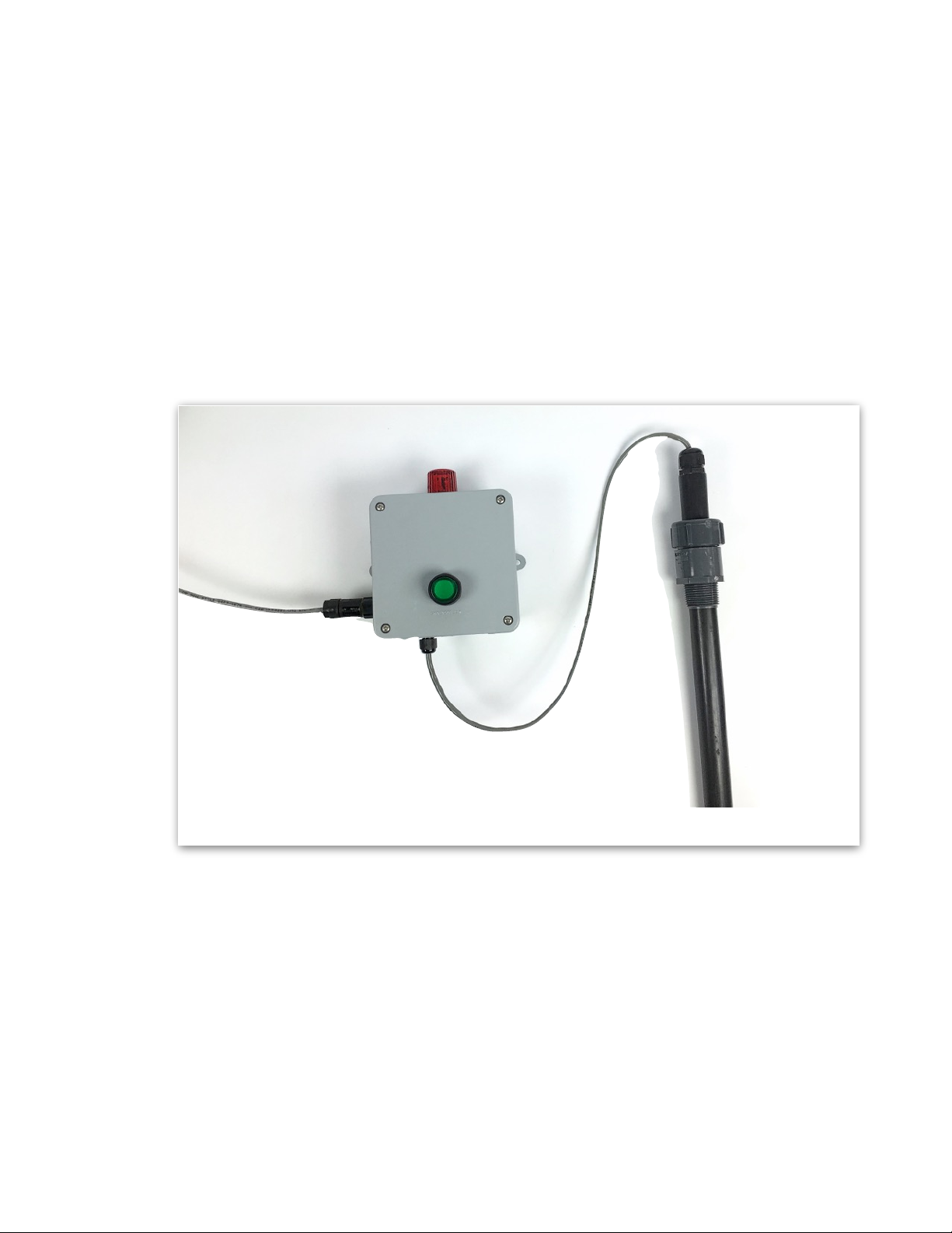
Install a level switch associated with the IS-AB on a tank or drum by screwing the mounting thread of the level
probe into the tank or drum opening.
Page of 2 4
IS-AB ALARM
RELAY OUTPUT TO
INTRINSICALLY
SAFE BARRIER
LEVEL “PROBE”
SCREWS INTO
TANK OR DRUM
Page 3
INTRINSICALLY SAFE ALARM IS-AB
7.
HAZARDOUS LOCATION SAFETY INFORMATION
MARKINGS
•
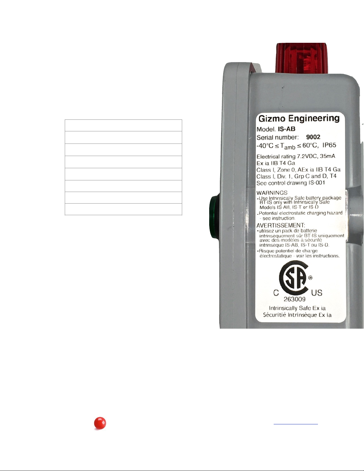
The following label will appear on the product indicating all the
relevant markings which are applicable.
ENVIRONMENTAL CONDITIONS
•
Outdoor, -40 to +60ºC, 2000m elevation.
APPLICABLE STANDARDS
•
This product has been certified to the following standards:
NOTES
•
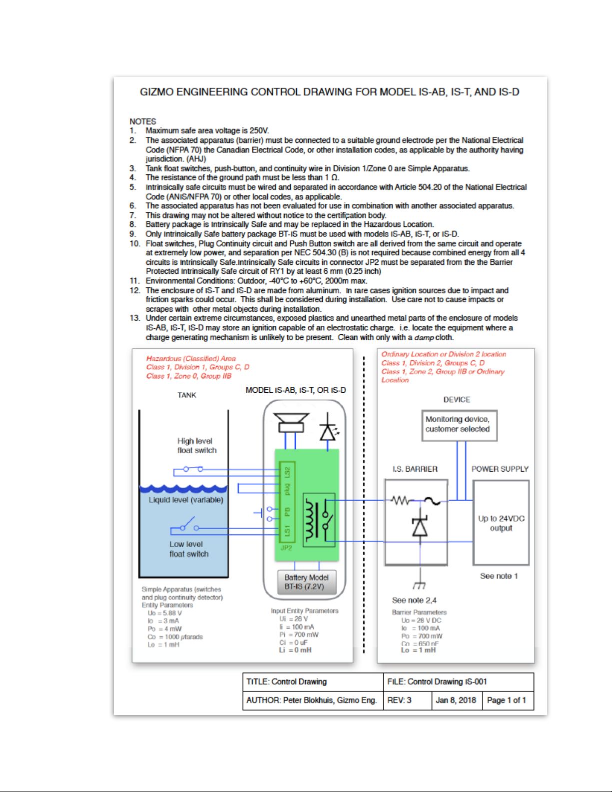
See the Control Drawing below.
Page of 3 4
Jan 10, 2018
Gizmo
2257 County Road 4, Building 3, Stanley, NY 14561 585-301-0970 www.drumalarm.com
Engineering
Customer Instruction number IS-AB-002
CAN/CSA-C22.2 No. 0-10
CAN/CSA-C22.2 No. 60079-0:15
CAN/CSA-C22.2 No. 60079-11:14
ISANSI/ISA-60079-0 (12.00.01)-2013
ANSI/ISA 60079-11 (12.02.01)-2014
CAN/CSA C22.2 No. 61010-1-12
ANSI/UL 61010-1, 3rd Edition
CAN/CSA-C22.2 No. 60529:16
LABEL
Page 4
INTRINSICALLY SAFE ALARM IS-AB
Page of 4 4
 Loading...