

Givi Misure VISION 700 Instruction Manual

INSTRUCTION MANUAL
FOR DIGITAL READOUT
MICROCOMPUTER
Measuring and control systems
Via Assunta, 57 - 20054 - Nova Milanese (MILANO)
(+39 0362/366126 +39 0362/366876 *sales@givimisure.it www.givimisure.it
10/06/2008 M042.E GQ
•1¥72
DECLARATION OF CONFORMITY “CE”
4
FOREWORD
5
INSTALLATION
6
DIMENSIONAL SPECIFICATIONS (STANDARD VERSION)
7
DIMENSIONAL SPECI
FICATIONS (PANEL MOUNTABLE VERSION)
7
CONNECTION OF CONNECTORS
8
KEY
-
MESSAGES AND SIGNALLING
10
RETENTION OF DATA AND PROGRAMS
13
VISION 700 MICROCOMPUTER
TABLE OF CONTENTS
USE OF STANDARD FUNCTIONS
INVERSION OF COUNTING DIRECTION
SCALE ZERO REFERENCE (rEF)
SELF-TESTING
ABSOLUTE/INCREMENTAL COUNT
RESETTING/PRE-SETTING A DIMENSION
MMS/INCHES CONVERSION
WORKPIECE CENTER
STORED DATA CLEARING
SETTING PRINTING LINE SPACINGS
CONSTANT PITCH
SUM FOR TWO AXES
LINEAR CORRECTION
NON-LINEAR CORRECTION (10 POINTS)
SCALE FACTOR
RADIUS/DIAMETER CONVERSION
VARIABLE RESOLUTION
SEXAGESIMAL DEGREE READING
CHANGING OF ANGULAR READING MODE
CALCULATING THE TAPER
AUTOMATICALLY CALCULATING THE TAPER
CALCULATING THREADS
CALCULATING THE WEIGHTS OF MATERIALS
CALCULATING THE TIP SPEED
CALCULATING THE ANGULAR SPEED
AUTOMATICALLY QUOTA SENDING ENABLING
CIRCULAR FLANGE
SPECIAL CIRCULAR FLANGE
LCD
LCD
LCD
LCD
LCD
LCD
F 0 EXE
F 9 EXE
F 26 EXE
F 28 EXE
F 30 EXE
F 31 EXE
F 32 EXE
F 34 EXE
F 36 EXE
F 37 EXE
F 38 EXE
F 44 EXE
F 46 EXE
F 48 EXE
F 50 EXE
F 52 EXE
F 54 EXE
F 55 EXE
F 64 EXE
F 66 EXE
•
•
•
•
•
•
•
•
•
•
•
•
•
•
•
•
•
•
•
•
•
•
•
•
•
•
•
•
•
•
•
•
•
•
•
14
15
16
16
17
19
19
20
21
22
23
25
26
29
30
31
32
33
34
35
36
37
38
39
40
41
42
10/06/2008 M042.E GQ
•2¥72
AUXILIARY LCD DISPLAY
66
TECHNICAL SPECIFICATIONS
67
WARRANTY CONDITIONS
68
USE OF STANDARD FUNCTIONS
INCLINED CONSTANT PITCH
ZERO APPROACHING ALERT
PROGRAMMING THE MEMORY BLOCKS
CENTRE OF A CIRCUMFERENCE
SPECULAR IMAGE
SCALE VALUE SET
AXIS SPEED DISPLAYING
INCLINED CONSTANT PITCH
DISPLAYING RECALLED TOOL
DEVICE DIAGNOSTIC
DISPLAYING W AXIS
100 TOOL OFFSETS
100 ORIGINS OF THE AXES
RECALL OF SPECIAL FUNCTIONS (F1-F6)
SETTING THE TYPE OF SPINDLE ROTATION SPEED
SELECTING A LANGUAGE
CALCULATOR
RS-232 SERIAL OUTPUT
LCD
LCD
LCD
LCD
F 68 EXE
F 69 EXE
F 70 EXE
F 72 EXE
F 74 EXE
F 78 EXE
F 80 EXE
F 81 EXE
F 82 EXE
F 89 EXE
F Z
STO
F REF
F nn Fn
F 98718 EXE
F 98762 EXE
CAL.
•
•
•
•
•
•
•
•
•
•
•
•
•
•
•
•
•
•
44
46
47
51
52
52
53
44
54
55
57
58
59
60
61
63
64
65
OPTIONS
MISCELLANEOUS
SPECIAL FUNCTIONS REQUIRED BY CUSTOMER
NOTES
10/06/2008 M042.E GQ
•
•
•
•
•
69
71
•3¥72
DECLARATION OF CONFORMITY
The Manufacturer: GIVI MISURE SRL
Address: VIA ASSUNTA, 57 - 20054 NOVA MILANESE (MI)
ITALY
Declares that the product: DIGITAL READOUT MOD.
Model: VISION 700
conforms to the following EC regulations including the latest
modifications and to relative national legislation:
• LOW VOLTAGE Directive 2006/95/EC and
98/37/EC (Enclosure III)
• ELECTROMAGNETIC COMPATIBILITY Directive 2004/108/EC
and the following harmonised rules have been applied:
EN 61010-1 Safety requirements for electrical equipment for measurement, control,
and laboratory use
EN 60529 Degrees of Protection Provided by Enclosures (IP Code)
EN 61000-6-3 Electromagnetic compatibility (EMC) - Part 6.3: Generic standards
EN 55011 Radio-frequency disturbance (ISM)
EN 55022 Radio-frequency disturbance (ITE)
EN 61000-6-2 Immunity for industrial environments
EN 61000-4-2 Electrostatic discharges
EN 61000-4-3 Radio-frequency radiated fields
EN 61000-4-4 Electrical fast transients/burst
EN 61000-4-6 Conducted disturbances, induced by radio-frequency fields
YEAR OF AFFIXING OF
PIERLUIGI GUERRA
Chairman
LABELLING: 95
10/06/2008 M042.E GQ
MARKING Directive
•4¥72
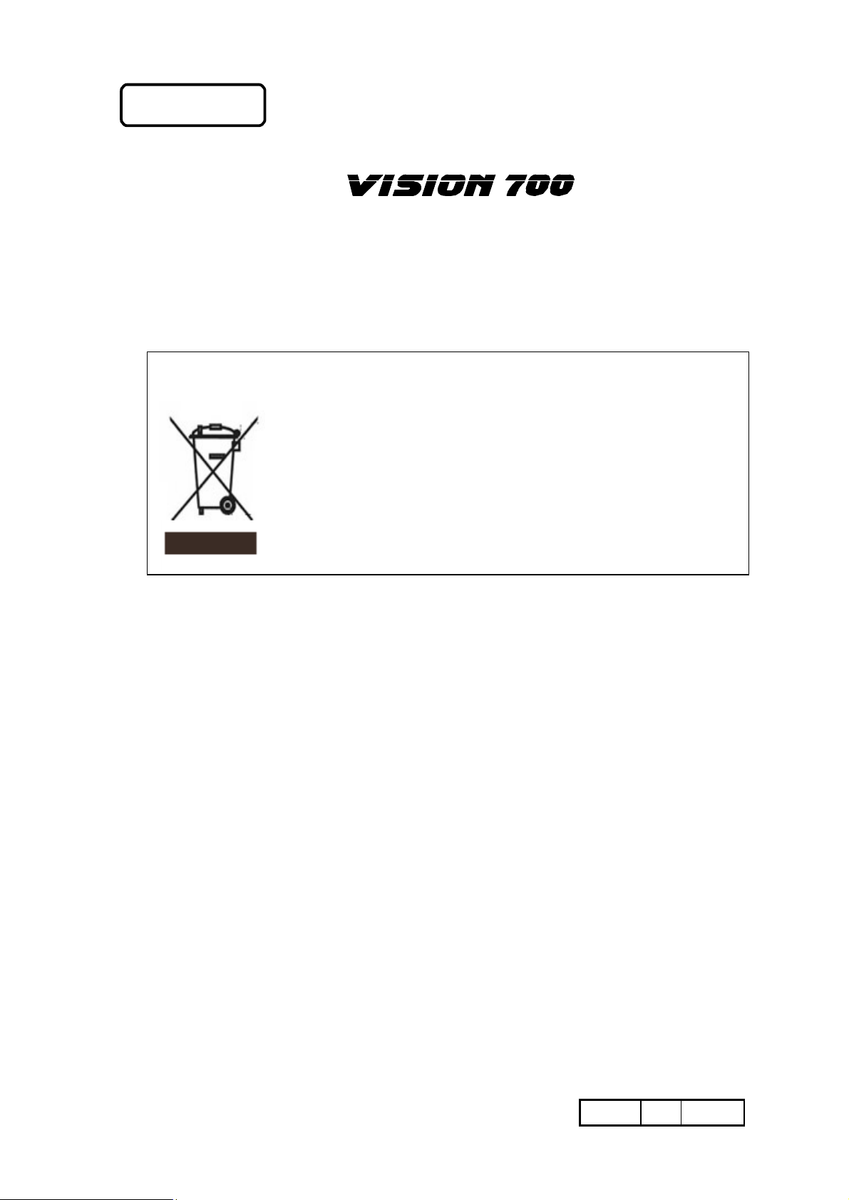
Dis
European Council Directive (2002/96/EC)
By ensuring this product is
disposed of correctly, you will help protect the environment. For
more detailed information about the recycling of this product,
please contact your local authority, your household waste
service provider or the retailer where you purchased the
FOREWORD
GIVI MISURE would like to thank you for purchasing the programmable digital
readout
MICROCOMPUTER
and to confirm that you have made an excellent choice.
Thanks to a powerful micro-controller, this instrument is fully programmable via the
keypad. This means that VISION can be optimised with a number of specific functions for
any type of machine-tool.
posal of old electrical & electronic equipment (WEEE)
The use of the WEEE Symbol indicates that this product may not
be treated as household waste.
disposal
product.
10/06/2008 M042.E GQ
•5¥72
INSTALLATION
W A R N I N G !
Do not switch on the instrument unless the machine conforms 98/37/EC
regulations.
The installation of the instrument must be carried out by authorised skilled
staff who will follow the regulations stated by the Manufacturer.
EARTHING The instrument is connected to earth by means of the power supply
PROTECTION According to power supply:
connector. In order to avoid discharges it is advisable to use an
earthed socket. If the instrument is not connected or is improperly
connected to earth, all the accessible parts, including those which
may appear to be protected, may generate electrical discharges.
Under no circumstances is it possible to access the inside of the
instrument when it is powered from the mains power supply or by
other power-supply devices.
q 230 Vac - 50/60 Hz or 110 Vac 60 Hz by fuse located on the
rear panel (use only delayed-action fuses, φ 5 x 20 mm, 500
mA 250 V).
q 24 Vac 50/60 Hz by an automatic brake circuit (self-
restoring), in case of overcurrent, short circuit and so on.
PREVENTION In order to avoid the possibility of fires or explosions, this
instrument may not be used in the presence of inflammable gases,
solvents, explosives, etc.
REAR This may be removed exclusively by specialised personnel, and in
PANEL any case after disconnecting the instrument from the mains power
supply (it is not sufficient to place the switch in the OFF position).
INSTALLATION Install the measuring scales (or rotary encoders) in accordance
with the Manufacturer’s instructions. Connect the Axis connectors
to the corresponding inputs (X,Y and Z) on the instrument. Connect
the power supply cable and then switch on the instrument (key-type
switch on the rear).
IMPORTANT NOTE: The instrument is protected against incorrect
information caused by uncertain situations (due, for example, to sudden or
momentary mains voltage drops). In these cases, in order to inform the operator
that an accidental upset of this type has occurred, when the instrument is switched
on again, it prompts the operator to find the scale zero (rEF).
10/06/2008 M042.E GQ
•6¥72
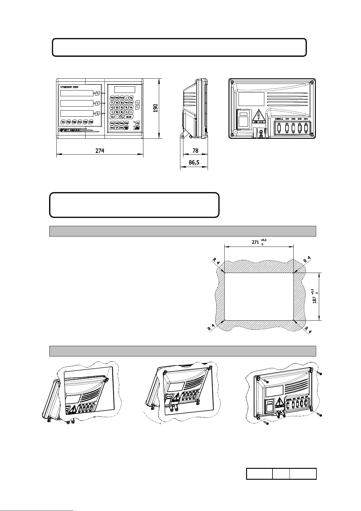
DIMENSIONAL SPECIFICATIONS (STANDARD VERSION)
DIMENSIONAL SPECIFICATIONS
(PANEL MOUNTABLE VERSION)
HOW TO PREPARE THE PANEL
Panel thickness reference : 2 ÷ 5 mm.
HOW TO ASSEMBLE IT
10/06/2008 M042.E GQ
•7¥72
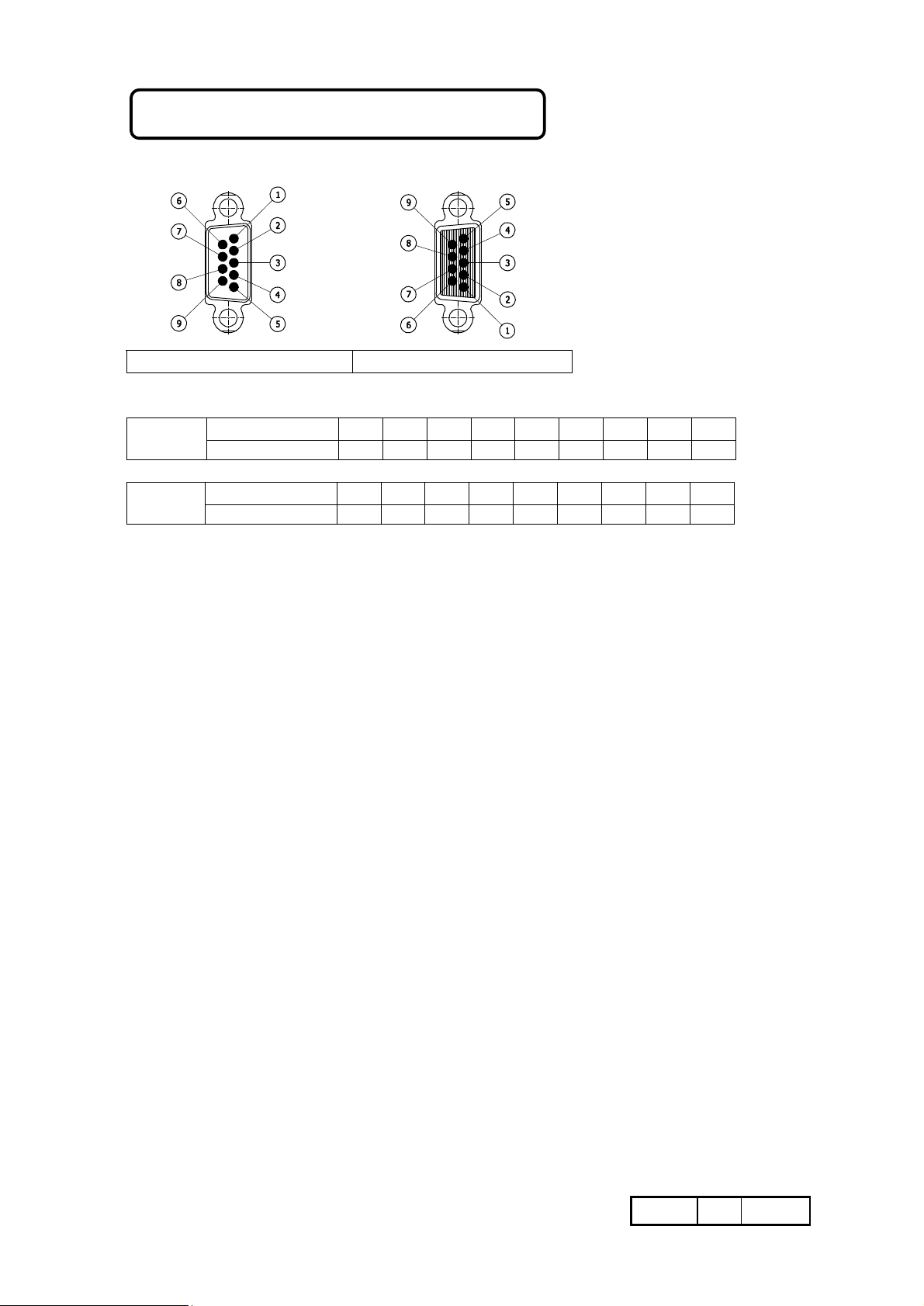
CONNECTION OF CONNECTORS
SERIAL IN1 / IN2 / IN3 / IN4
SERIAL
Reference number
Signal / RX TX / GND / / / /
1 2 3 4 5 6 7 8 9
IN1-IN4
Reference number
Signal B / Z A / / V+ GND SHD
1 2 3 4 5 6 7 8 9
10/06/2008 M042.E GQ
•8¥72
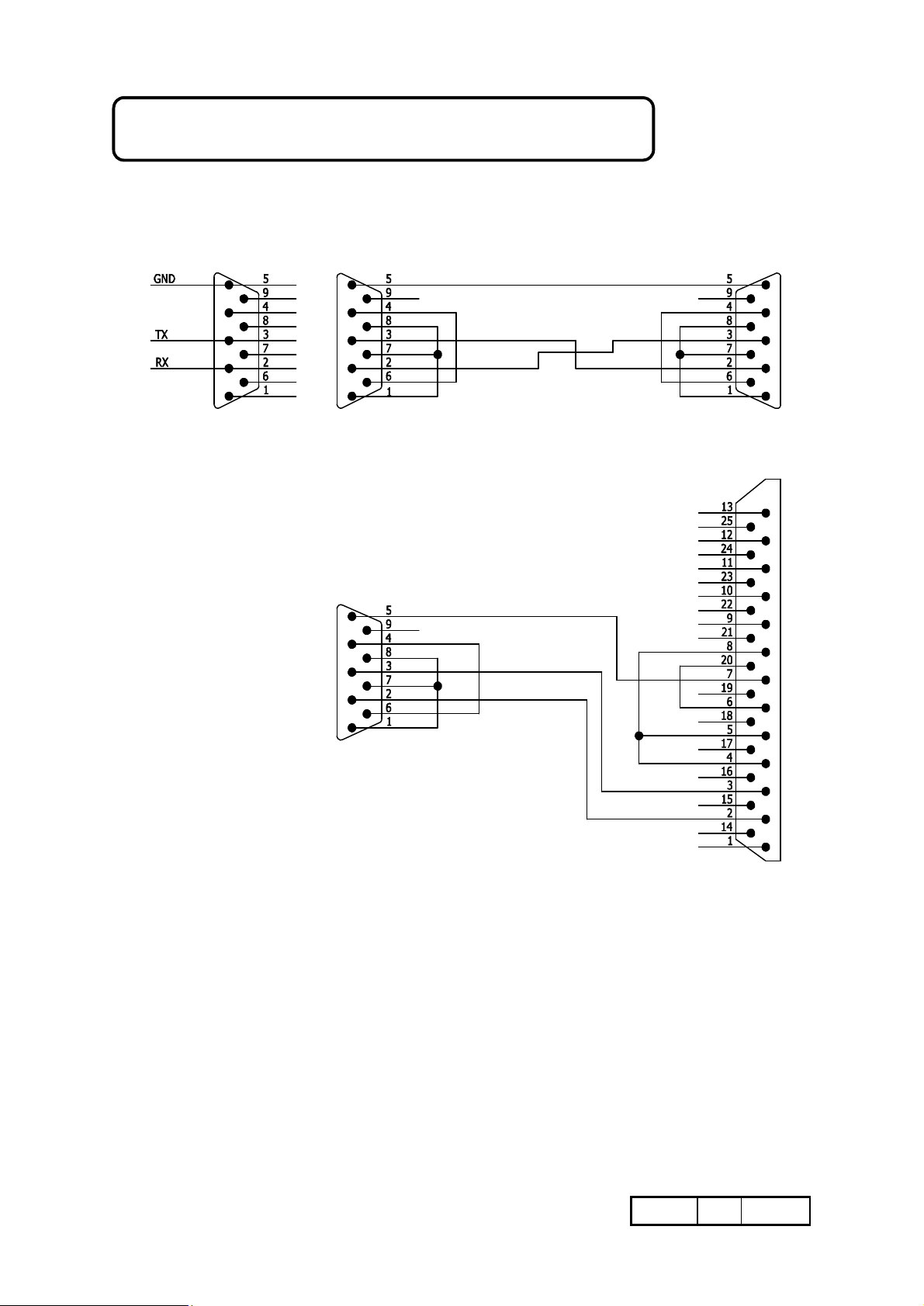
VISION – PC CONNECTIONS
VISION – SERIAL PRINTER CONNECTIONS
CONNECTOR
(RS-232) TO VISION CONNECTION CABLE
10/06/2008 M042.E GQ
•9¥72
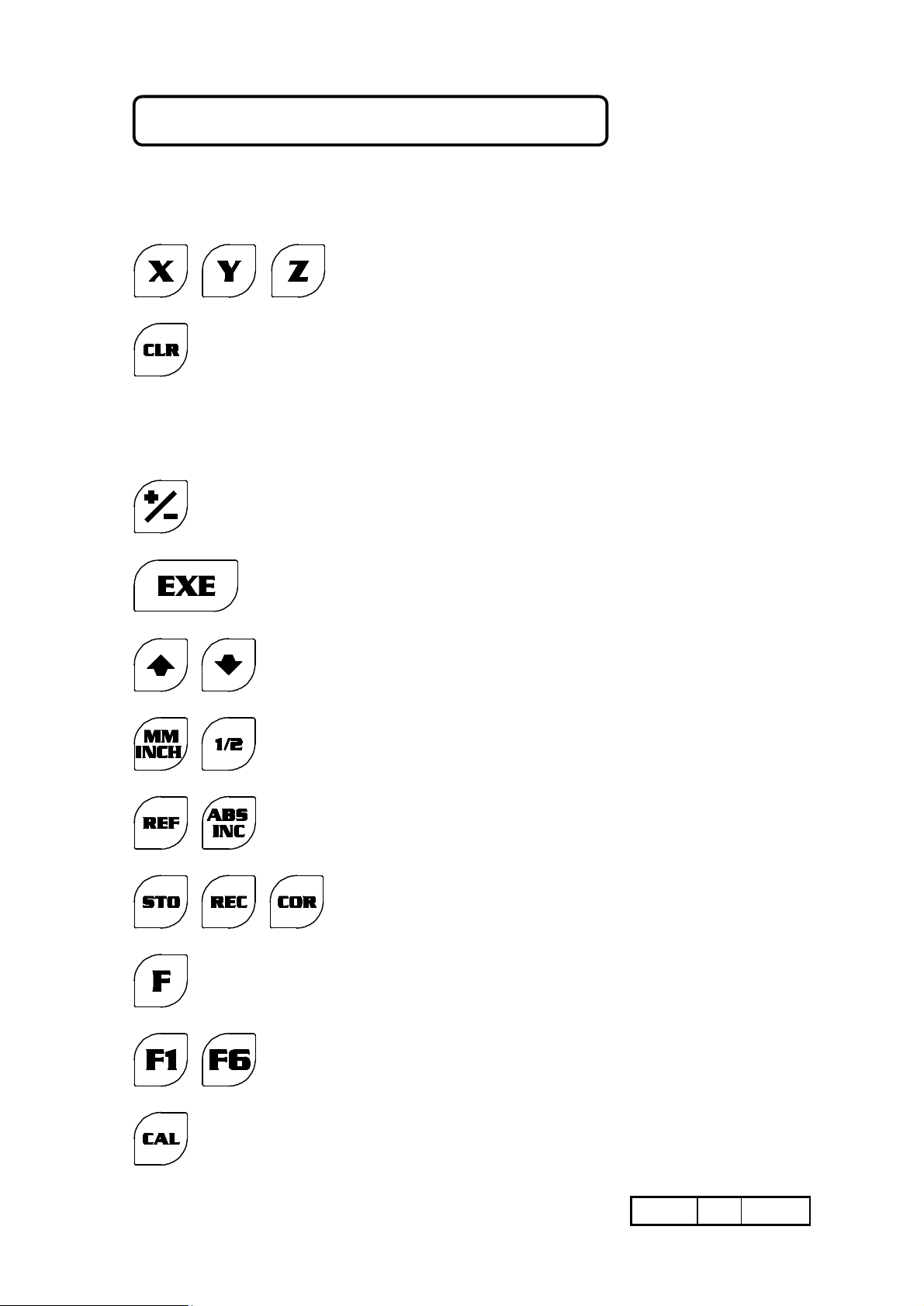
KEY - MESSAGES AND SIGNALLING
In the manual, the following graphic (or numerical) symbols are used to indicate :
1 3 3 . 0 5
X, Zo OR Z AXIS KEYS
KEY FOR RESETTING THE CORRESPONDING AXIS.
OR CLEAR THE OPERATION
DIGIT TO BE ENTERED VIA THE NUMERICAL KEYPAD.
KEY FOR ALGEBRAIC SIGNS. USED IN SOME CASES TO
“CHANGE THE PROMPT”.
TO CONFIRM THE SELECTION
KEY USED TO “CHANGE THE PROMPT” DURING
OPERATION OF SELECTION DATA.
SPECIAL FUNCTION KEY. THE INTERNAL INDICATION
SHOWS THE FUNCTION .
SPECIAL FUNCTION KEY. THE INTERNAL INDICATION
SHOWS THE FUNCTION .
STORE / RECALL AND SHOW MEMORY PROGRAMS.
FUNCION CODE KEY (USE BY NUMERIC CODE).
PROGRAM KEY TO RECALL FUNCTIONS.
TO RECALL CALCULATOR FUNCTION.
10/06/2008 M042.E GQ
•10¥72
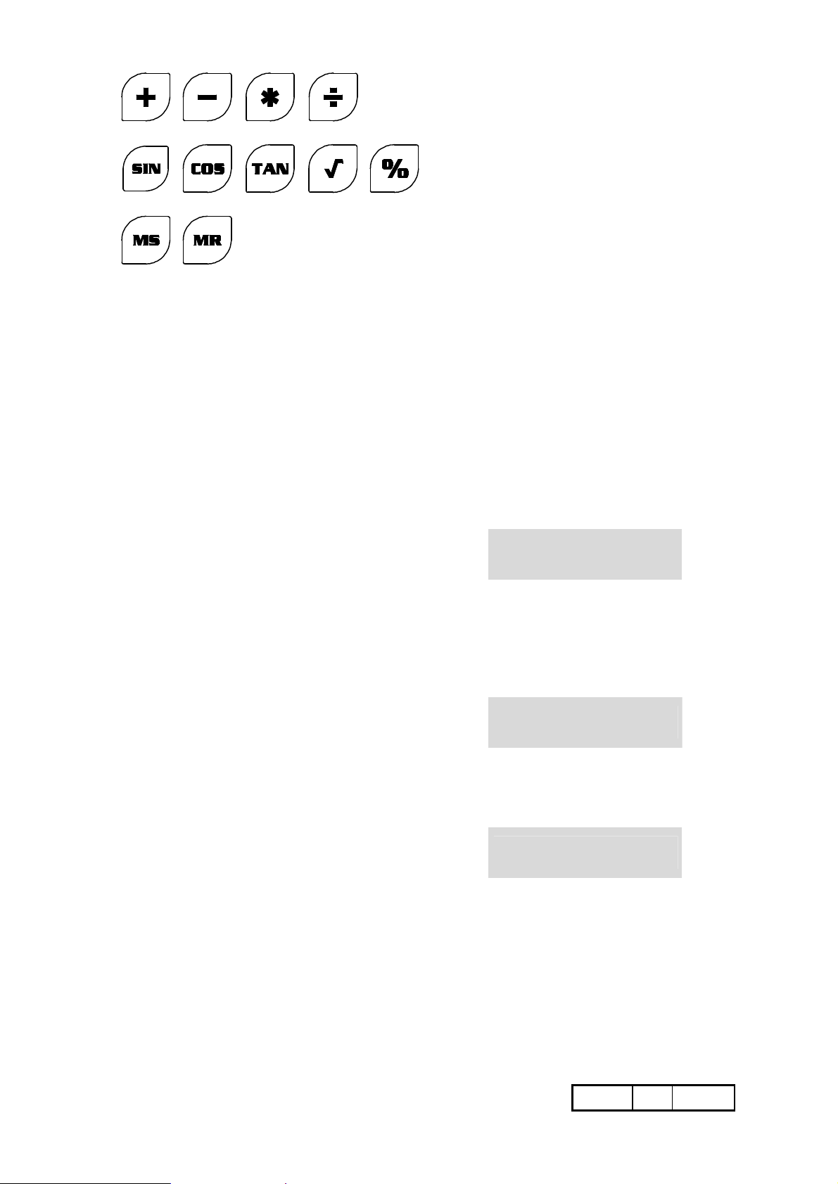
FUNCTION KEYS (CALCULATOR)
To exit from this type of situation, see
FUNCTION KEYS (CALCULATOR)
MEMORY KEYS (CALCULATOR)
® FLASHING AXIS LED ˜ STEADY AXIS LED
The instrument provides a series of acoustic and visual signals to indicate the succession of
the settings. Every time a key is pressed, a “short” sound of a buzzer is heard, while
messages consisting of wordings or numbers appear on the display depending on the type
of setting made (see manual). Finally, the Axis LED underlines the activation of the axes
or that they have been set to perform (or to have performed) a given function. If the LED
flashes, the function is in progress, while if it is steadily lit (or if it extinguishes), the
function has been completed and performed.
In the event of incorrect entries, an acoustic alarm consisting of a “long” buzzer signal will
occur, accompanied by a visual alarm consisting of the following message:
E r r o r
This appears momentarily on the display in order to inform the operator that he has
pressed a key which is not compatible with the operation being carried out.
In the event of “overflow” errors, which occurs if measurements having a number of
digits greater than the counting capacity of the instrument are entered, the error is
indicated on the display as follows :
page 17
Some bad condition uses are shown by a numerical message
For example :
_ _ _ _ _ _ _ _
E r r o r 20
10/06/2008 M042.E GQ
•11¥72
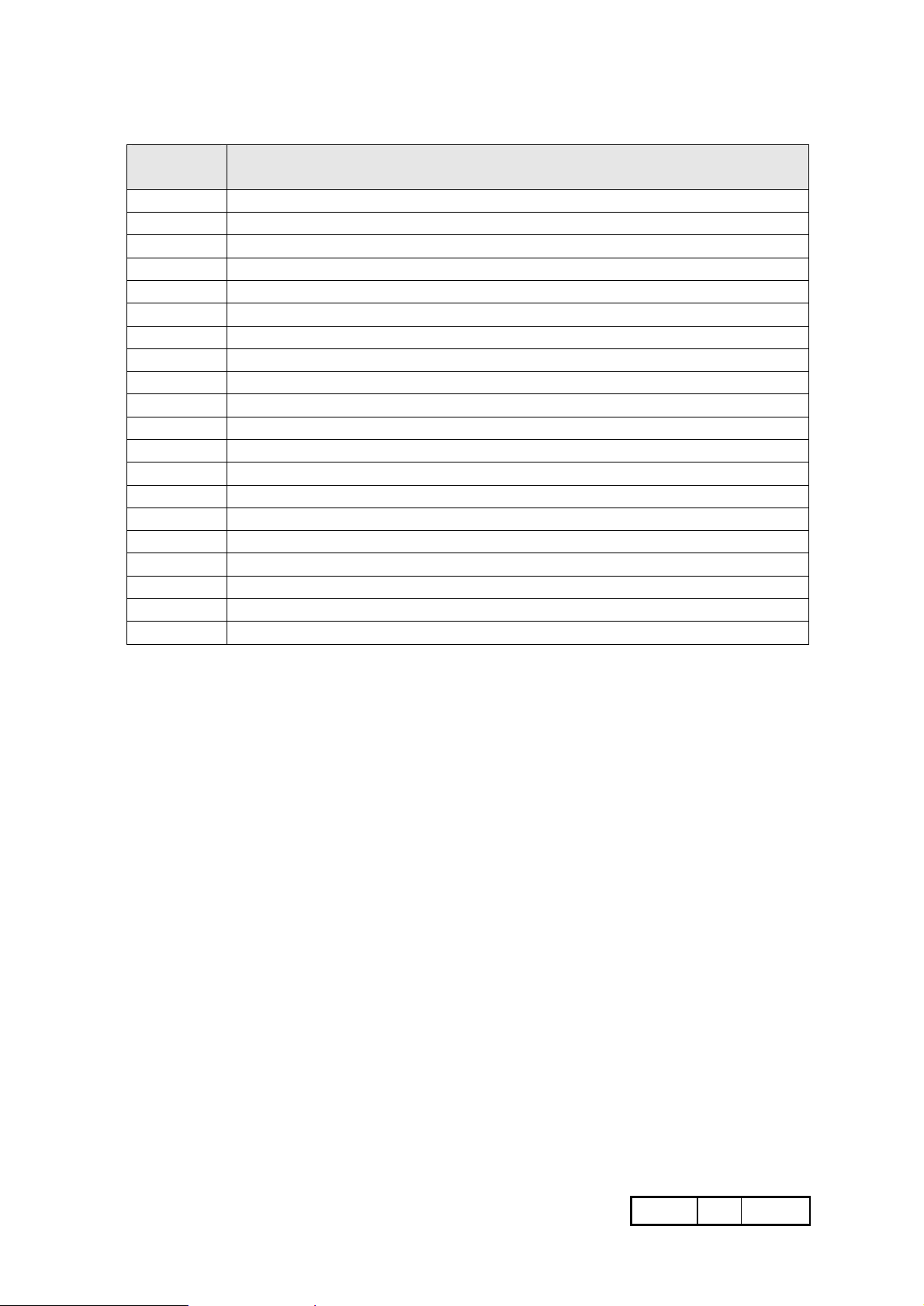
Message list error:
Error ref.
N.
10
11
12
20
21
22
23
28
80
81
90
E0
Start researching reference positions (rEF)
Axis set up not in “Linear” reading mode
Axis set up not in “Angular” reading mode
Function not allowed
Key button not programmed
Program not allowed
Memory end
Algebraic sum entered
LCD display required
Sum of two axes required
Internal fault (service required)
Wrong configuration (service required)
Description
10/06/2008 M042.E GQ
•12¥72
RETENTION OF DATA AND PROGRAMS
Program setting of VISION is carried out beforehand by the Manufacturer, who is aware
of the access codes and of the procedures (configuration). The user can then enter the
settings required for using it. All the information is permanently stored, and can only be
changed voluntarily, by re-entering it. The instrument is also able to “remember” the last
piece of data acquired, when the power supply is switched off.
In addition to the information referred to above, the following will
also be retained:
A) The selected unit of measurement (MM/INCH).
B) Confirmed function settings, with the exception of the scale
factor and variable resolution.
C) The last Axis counting position, and any messages (not of the
transient type) indicating abnormal situations, such as :
_ _ _ _ _ _ _ _
To clear all the “operational” settings entered (resetting of counters, origins of the Axes,
tool offsets, etc.) see function “F0”
IMPORTANT Either the instrument is in the ABS or the INC mode, it is unable to
consider any shifting of the Carriages (due to inertia, manual
repositioning or thermal expansion) when there is no power supply. If
this occurs, the measurements indicated on the display will no longer
be reliable, since they will be unable to show the new position of the
Carriages but only the one before the instrument switched off.
In order to avoid errors, which may be even considerable, the operator
must consider the opportunity of relating the ABS/INC counting mode
to the scale zero reference (rEF). He will link to rEF all those functions
which he intends to use and which require this condition, as specified in
the descriptions related to the single functions (it is recommended that
these descriptions are carefully read).
10/06/2008 M042.E GQ
•13¥72
the selection is confirmed
and the X axis has been
while for the Z Axis, which has
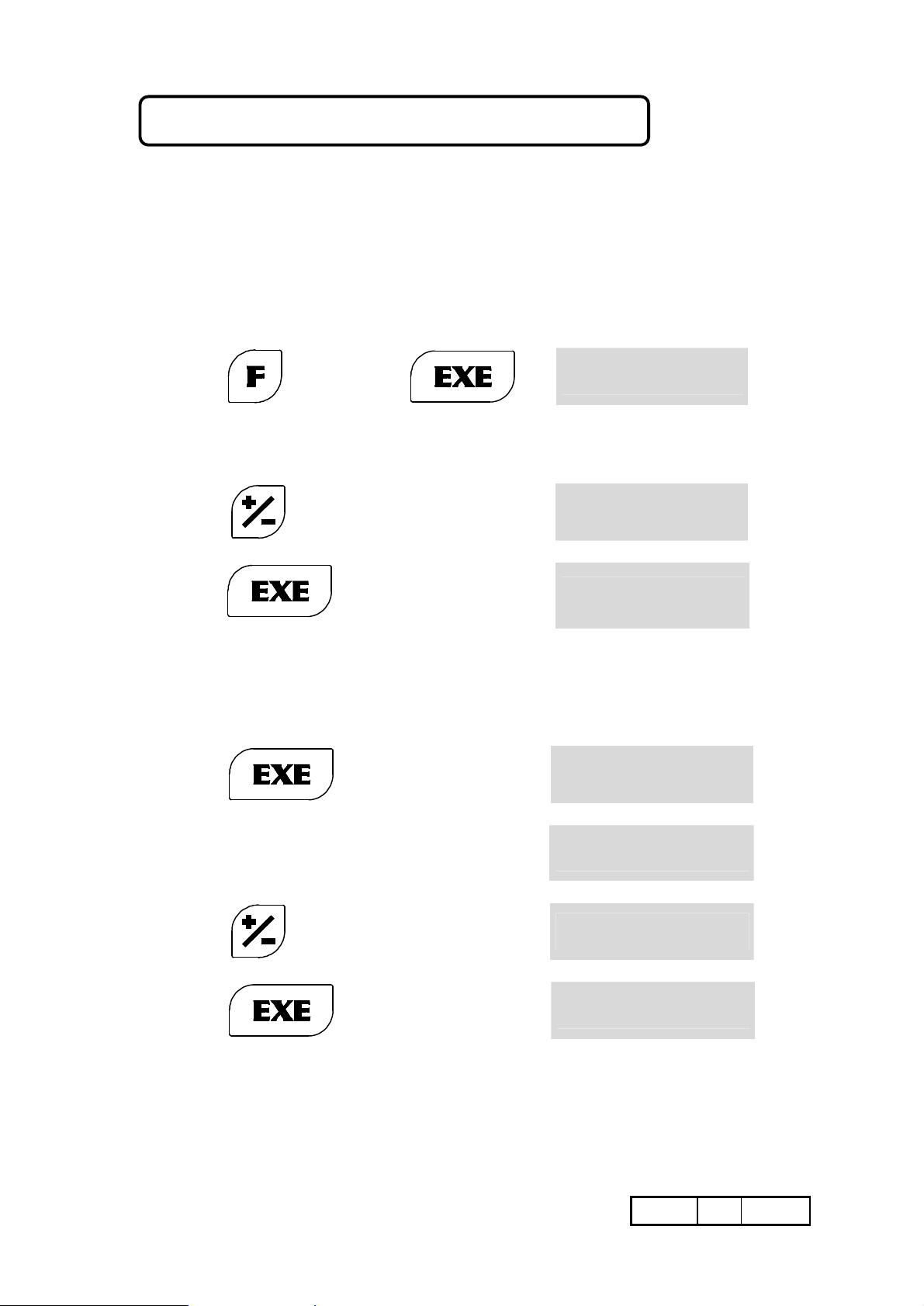
INVERSION OF COUNTING DIRECTION
Switch on the instrument and wait for the end of the self-test cycle.
The displays remain on and show the zero search (rEF). Press CLR to enable the Axes for
counting. Move the Carriages by hand and decide which Axes need to be reversed (the
direction in which they advance depends on the mode of application of the rulers, and is
therefore random).
EXAMPLE X AXIS = TO BE REVERSED
Y AXIS = CORRECT
Z AXIS = TO BE REVERSED
PROGRAMMING THE AXES :
Key
The LED of the X Axis will then start to flash. The position of the dash (-) is purely
indicative.
press
press
Once the operation has been completed, the instrument automatically goes on to consider
the next Axis (the LED of the Y Axis will start to flash).
Since, based on the example, this does not have to be reversed :
press
98722
(because it has to be reversed)
reversed.
to be reversed:
1 d i r -
1 - d i r
1 - d i r
2 d i r -
3 d i r -
®X
®X
X
Y
®Z
press
press
On pressing EXE to confirm the last entry, the programming mode will be exited (all the
displays indicate dimensions). In the event of a wrong setting, press the CLR key and start
from the beginning again.
10/06/2008 M042.E GQ
(because it has to be reversed)
3 - d i r
X X X. X X
®Z
Z
•14¥72
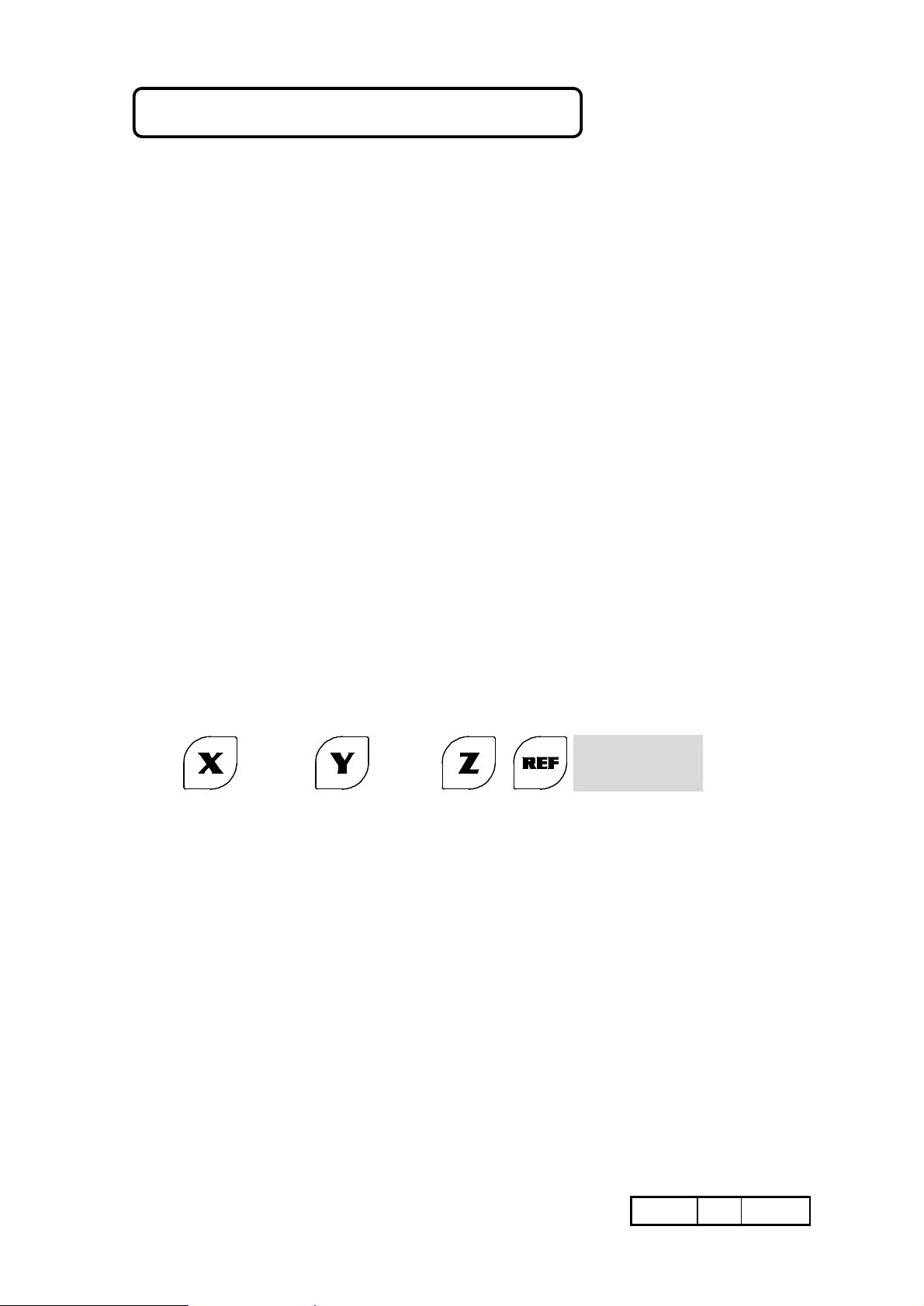
SCALE ZERO REFERENCE (rEF)
The ruler zero reference (rEF) can be considered a precision micro-contact, generally
located at the midpoint of the travel. Its position in relation to the geometrical trim of the
machine is invariable in time, and can only “move” if the scale is disassembled (for
servicing, maintenance or replacement), and re-assembled differently. In this case the
operator will have to set the references again. When using scales with reference marks at
coded distance, the research of rEF is completed after a travel of appr. 20 mm on the
travel direction. Note: for a correct rearrangement of rEF position, on scales with
reference marks at coded distance, it is important to properly set the counting way,
according to the installation instruction. The zero rEF can be searched either in
automatic mode, every time the instrument is switched on, or in manual mode:
A) Automatically, every time there is a momentary or long-lasting interruption of
the mains power supply, either voluntary or otherwise, in order to avoid presenting
the operator with incorrect numerical values (LAST POSITION), the instrument
displays a prompt to the operator suggesting a new scale zero (rEF) search. This is
the case, for example, in the event of a sudden power failure occurring while the
Carriage is moving (since it would continue to move due to inertia), or movements
due to thermal expansion (due, perhaps, to a temperature drop at night), or
involuntary or accidental shifting (while cleaning the machine, for example). In this
way, the operator is warned that there is a probable “risk situation”. He may decide
to carry out a scale zero (rEF) search by passing the Carriages over the
corresponding points, or else to cancel the scale zero by pressing CLR (this should
be done in any case if the rulers do not have the ruler zero reference. In this case it
is advisable to check the precision of the positions reached).
B) Every time the operator thinks that it is necessary, he can check the positions
reached by the Carriages by setting the scale zero (rEF) search manually on the
Axes concerned (or on all the Axes).
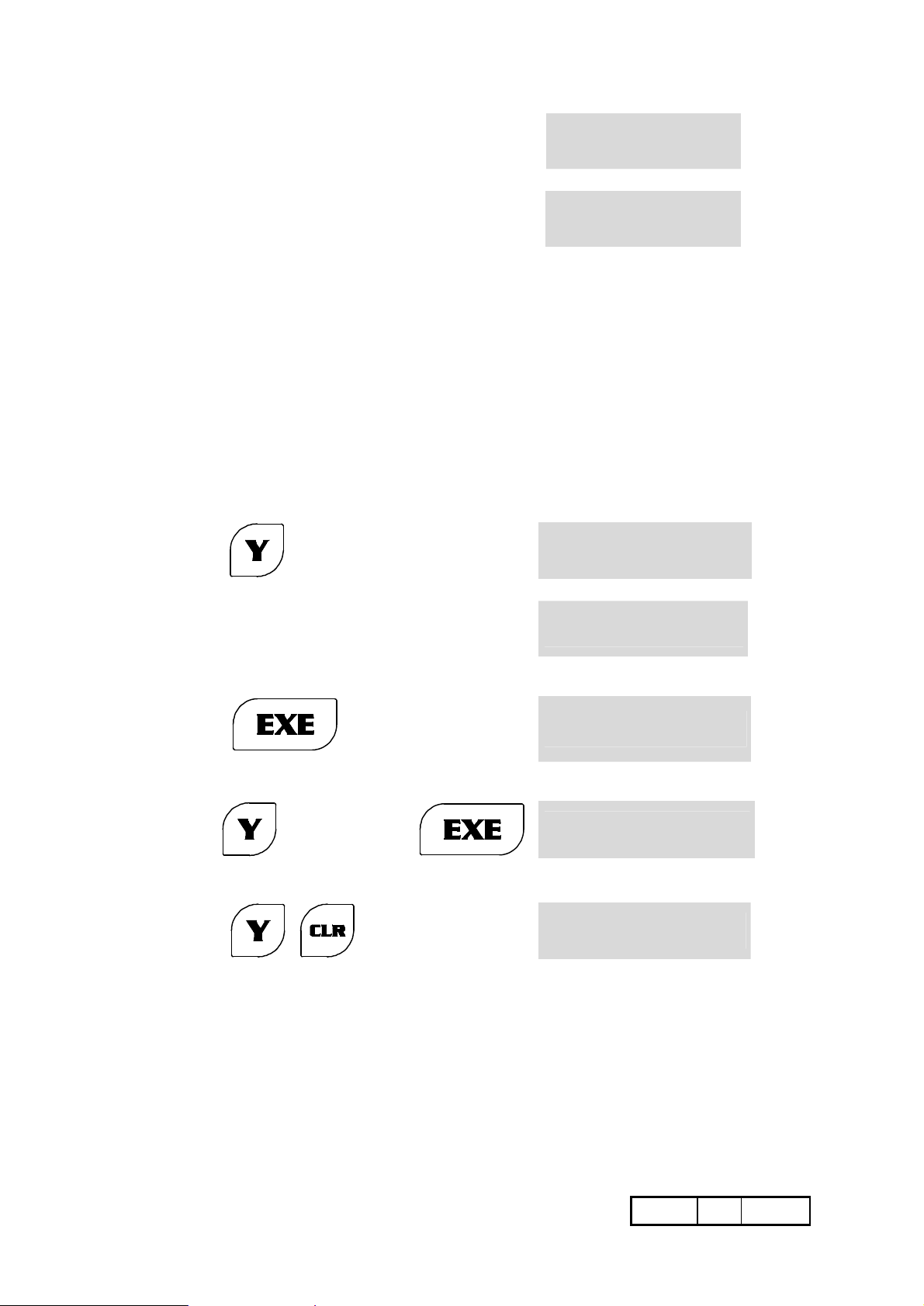
For example enter:
X and/or
Key
The LEDs of the activated Axes flash and indicate that the instrument is ready
for the scale zero (rEF) operation.
and/or
and/or
r E F
®Yand/or
Z
NOTES: Every time an Axis completes the ruler zero (rEF) search, it is automatically excluded
from this function so that it will not interfere with the other operating conditions. In any
case, the instrument will not accept any settings until all the Axes have terminated the
ruler zero (rEF) search, and will display an error message if any keys except CRL are
pressed. The operator may then decide to proceed as follows:
A) to complete the zero search for all the Axes activated;
B) to carry it out for the Axis concerned and cancel it for the remaining Axes;
C) to cancel the search right away for all the Axes because it is considered superfluous.
10/06/2008 M042.E GQ
•15¥72
SELF-TESTING
A general test of the instrument is carried out every time it is switched on, and the validity
of the data stored in the memory is checked. If this is found to be reliable, while the
function is being performed the following wording will appear on the display for a few
seconds:
t E S t
®X
n o E r r o r
®X
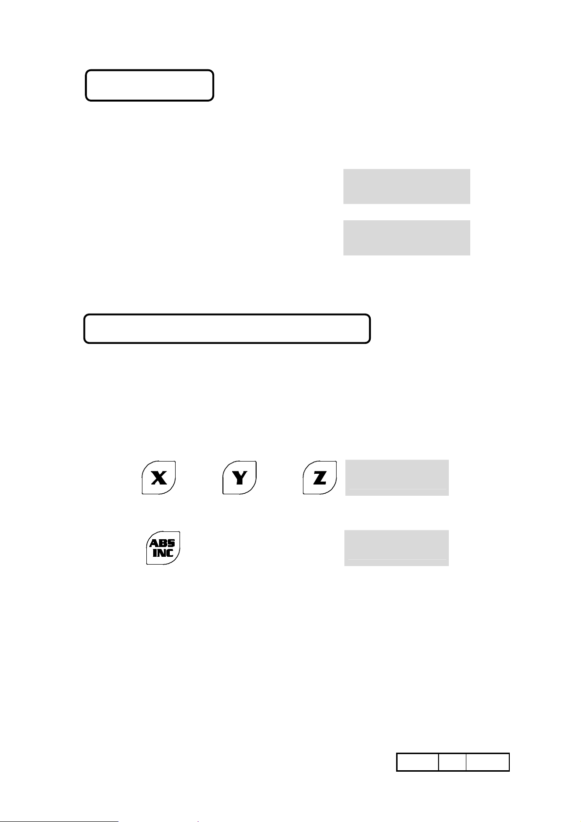
ABSOLUTE/INCREMENTAL COUNT
The LED of each Axis always signals the following:
• AXIS LED ON = AXIS IN ABSOLUTE COUNT (ABS) MODE
• AXIS LED OFF = AXIS IN INCREMENTAL COUNT (INC) MODE
• AXIS LED WILL FLASH = FUNCTION BEING PERFORMED
It is possible to switch either a single Axis or all the Axes from one counting mode to the
other as follows :
X and/or
key
The LEDs of the activated Axes will flash
press
The LED will light up (or extinguishes) and signal that the Axis is in ABS (or INC) mode.
The counting system is managed by the instrument, which has a dual internal counter
(ABS/INC) for each Axis. The information relating to the movement of the Axis updates
both counters at the same time. The information entered by the operator, on the other
hand, only affects the counter of the selected counting system. It goes without saying that
if the ABS counter is reset at a given point of the travel (ORIGIN) and the
INCREMENTAL counting mode is used (this is handier and more versatile to use), the
operator can then carry out all the resetting, pre-selections, functions and so on required
by the machining process, since he can return to the ABS count at any time to find out the
“absolute” positions of the Carriages at that time and thus find the ORIGINS which had
been set.
10/06/2008 M042.E GQ
and/or
and/or
1 2 3. 4 5
1 2 3. 4 5
®Yand/or
Z
˜X
•16¥72
without the decimal
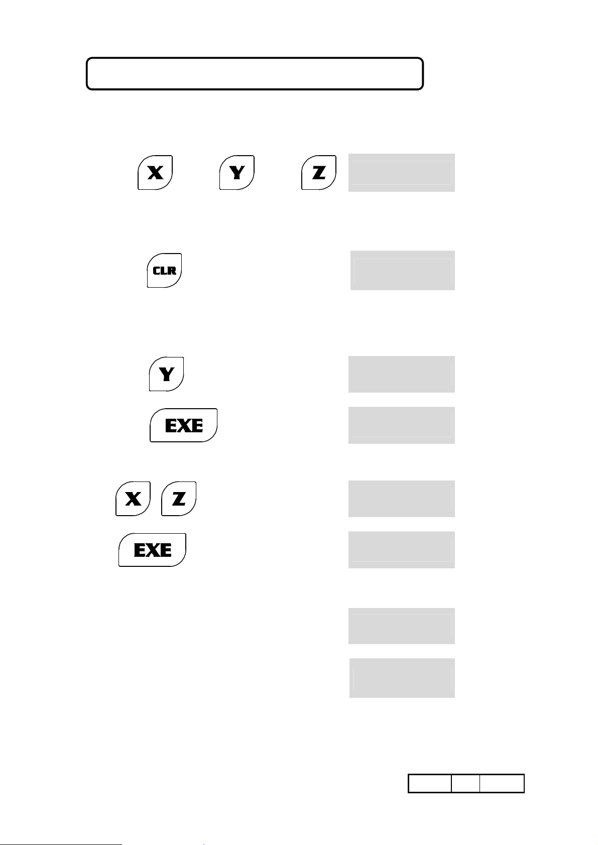
RESETTING/PRE-SETTING A DIMENSION
Regardless of the selected counting mode, ABS or INC, resetting of a datum is obtained
by proceeding as follows :
Key
The LEDs of the activated Axes will flash.
press
To enter a (pre-set) datum, for example 113.03, on the Y Axis:
Key
press
and/or
and the datum will be reset
and/or
113.03
1 2 3. 4 5
0. 0 0
1 2 3. 4 5
1 1 3. 0 3
X and/or
®Yand/or
Z
X and/or
Yand/or
Z
®Y
Y
If the same datum has to be entered for more than one Axis, for example
100.05 for both Axes X and Z, proceed as follows:
Key
press
ON EACH DISPLAY THE DATA CAN BE ENTERED:
a)
zero references which
are not significant:
b) with a number of
relevant decimal
digits:
100.05
and the datum will be reset
1250
1133.04
1 0 0. 0 5
1 0 0. 0 5
1 2 5 0. 0 0
1 1 3 3. 0 4
®X and Z
X and Z
10/06/2008 M042.E GQ
•17¥72
In any case, the data entered is rounded off:
- downwards:
- upwards:
c) With a total number of digits not exceeding the counting capacity of
the instrument (7 digits with a sign and the decimal point) that
means:
-999999.9 with decimal resolution
-99999.99 with a resolution of hundredths
-9999.999 with a resolution of thousandths
Attempts to enter a higher number of digits will take to an “overflow” error.
Let us suppose that the datum 123456.78 has to be entered for the Y Axis.
We will proceed as follows:
Key
from 13.051 to 13.054
from 13.055 to 13.059
123456.78
1 3. 0 5
1 3. 0 6
E r r o r
X
If we attempted to enter it in any case by pressing :
It is possible to quit this situation correctly as follows:
Key
or by resetting the Axis:
Key
d) With the negative algebraic sign entered during or on completion of the
ACOUSTIC ALARM
the datum would not be
accepted
(“overflow” error)
1 2 3 4 5 6. 7
_ _ _ _ _ _ _ _
XXXXX.XX
(correct datum)
datum entry (is understood the positive sign has been entered and in any
case it is never shown on the axis display).
XXXXX. XX
0. 0 0
®Y
Y
Y
Y
10/06/2008 M042.E GQ
•18¥72
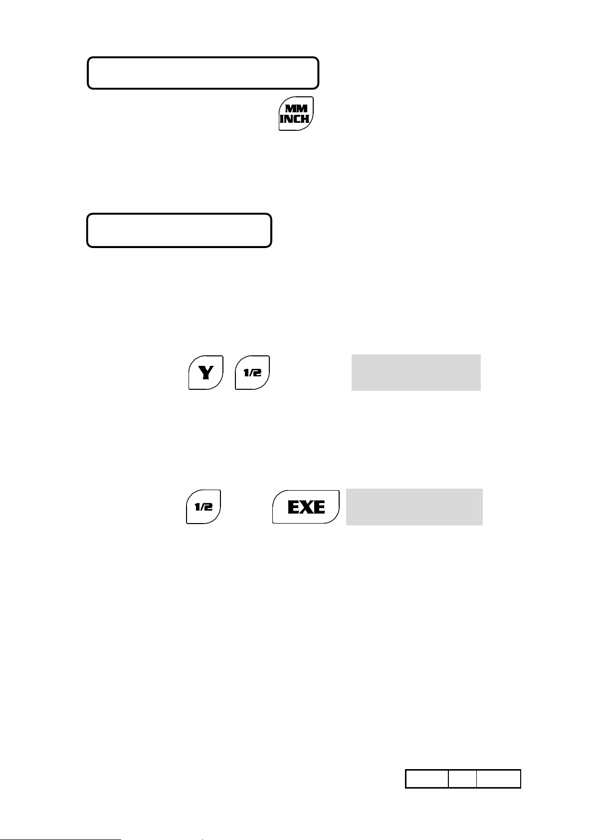
MMS/INCHES CONVERSION
Every time the following key is pressed the unit of measurement is switched from
MM to INCHES or vice versa. Switching takes place instantaneously for all the Axes
being counted. The selected unit of measurement is shown by the position of the LED lit
on the keypad, and also by the position of the decimal points for the Axes being counted.
If activation of the conversion is not compatible with the operational conditions of the
instrument, pressing this key will cause an error message to be displayed.
WORKPIECE CENTRE
This function makes it easy to identify the centre between two points A and B of a
workpiece being machined (distance between centres of holes, geometrical figures, sides
of the workpiece, etc.). To perform the function, for example on the Y Axis, proceed as
follows:
A) Go to the first position, A, by moving the Carriage along the Zo Axis.
Let us suppose that in this position the display of the Y Axis indicates
the dimension 30.00 (which it is not necessary to reset):
B) Key
Both the LED of the Y Axis and the LED of the ½ symbol will flash on the keypad.
The auxiliary display will show the wording “WORKPIECE CENTRE”.
C) Now go to the second position, B. Let us suppose that in this position the display of
the Y Axis shows the dimension 52.22
D) Key
The flashing LEDs will extinguish and a dimension will appear on the display of the
Zo Axis. This dimension is exactly half (rounded off, if necessary) of the path followed
by the Carriage between the two positions A and B. It will be sufficient to move the
Carriage as far as dimension “0.00” for it to be located exactly on the required
midpoint.
or
3 0. 0 0
1 1. 1 1
®Y
Y
NOTE: This function can only be carried out when the Axis concerned is set for
INCREMENTAL counting. Otherwise it is not completed by the calculation, as
this would interfere with the ABSOLUTE count settings.
10/06/2008 M042.E GQ
•19¥72
0
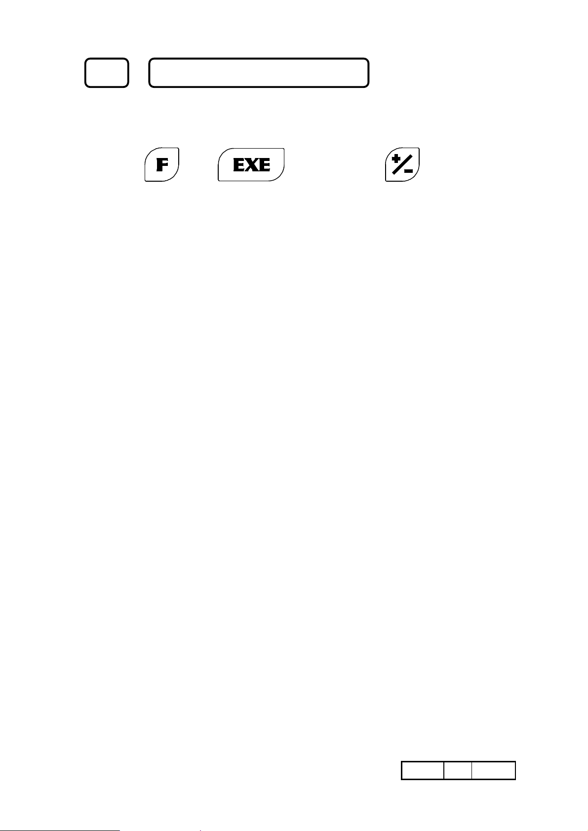
F 0 STORED DATA CLEARING
This function can be used to cancel the data entered by the operator, either globally or
selectively. The instrument has placed them in 11 different storage areas.
Key
and, if required
The indications concerning the types of data stored in the memory areas will be displayed,
together with the number corresponding to each area. If the keys indicated are pressed on
the keypad of the instrument:
All the data stored is cancelled.
1:
The data concerning linear corrections
2:
and scale factor corrections is cancelled
and these are reset to a value of 1 (that
10:
11:
Rotation speed is deleted
8:
Inclined constant pitch is deleted
9:
Circular flange is deleted.
Special circular flange is deleted
is to say, no correction).
Both the absolute and the incremental
3:
dimensions and references are cancelled.
The offsets are cancelled.
4:
The origins are cancelled
5:
The weight of materials is cancelled.
6:
The constant pitch is cancelled.
7:
Every time one of the numbers indicated above is pressed, the function will be carried out,
while for the functions without a code it is necessary to enter EXE.
10/06/2008 M042.E GQ
•20¥72
9
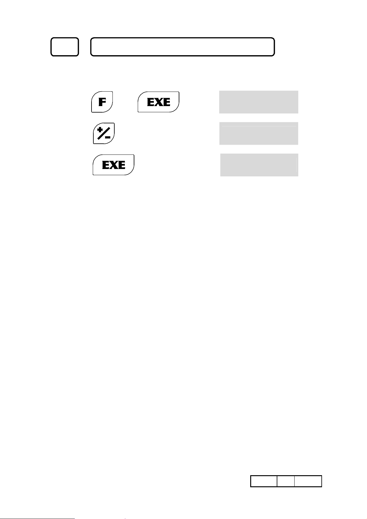
F 9 SETTING PRINTING LINE SPACINGS
When printing the labels (see SERIAL OUTPUT RS232), it is possible to set some
spacings among the printing lines (max .19), for the correct position on the labels.
To set the number of spacings, select function F 9.
Key
P r t. 0
X
press
press
Printer example (4 spacings) :
-------------- 1 spacing -------------->
-------------- 2 spacing -------------->
-------------- 3 spacing -------------->
-------------- 4 spacing -------------->
To increase the number (0-19)
To confirm the setting
P r t. 1
5 7. 0 8 6 5
= DIGITAL READOUT =
AXIS X : 57 . 0865
AXIS Y : 10 . 8480
AXIS Z : - 7 . 0985
UNIT : INCH
= DIGITAL READOUT =
AXIS X : 57 . 0865
AXIS Y : 10 . 8480
AXIS Z : - 7 . 0985
UNIT : INCH
X
X
10/06/2008 M042.E GQ
•21¥72

F 26 CONSTANT PITCH
This function is used to process workpieces having a constant machining pitch. Let us
suppose, for example, that six holes having a pitch of 13.75 mm have to be drilled:
Key
The instrument signals the operator to move the Carriages until the Origin of the 1st hole is
reached.
Key
Key
The instrument goes on to consider the other Axes. Enter the values or continue to press
EXE until you return to the initial X Axis (the LED on the X-Axis display flashes). Make
the first hole (the X-Axis display must indicate the dimension Zero. If this is not so, move
the Carriages to Zero).
Key
Follow the Zero with the Carriage and make the second hole Proceed as described until
the workpiece has been completed. If it is not necessary to repeat the same operation on
other
workpieces, press CLR. If it is, press REF. The display will indicate the total value of the
last
position reached, that is to say:
13.75 x n° 5 pitches = 68.75 (return to Zero with the Carriage, enter X and start
again)
When working it is possible to reverse the pitch direction for each axis:
13.75
26
and enter the value of the
pitch
The X display show the value
and the X Axis
display will be
reset
O r i G.
S t E P
0. 0 0
- 1 3. 7 5
®X
®X
X
®X
press
It must be remembered that:
A) The counting direction must be the same as the direction of displacement (if
necessary, use +/- to reverse it while entering the pitch, that is to say: 13.75 +/-
EXE).
B) Carrying out holes in succession does not lead to errors of the “cumulative” type,
even if the positions have not been reached with great accuracy by the operator.
C) It is not possible to perform any other functions during this operation.
10/06/2008 M042.E GQ
ex. inversion of X axis direction
- CONSTANT PITCH -
PITCH X: 1 ß
•22¥72
 Loading...