

Givi Misure THESI 310 User Manual
User Manual
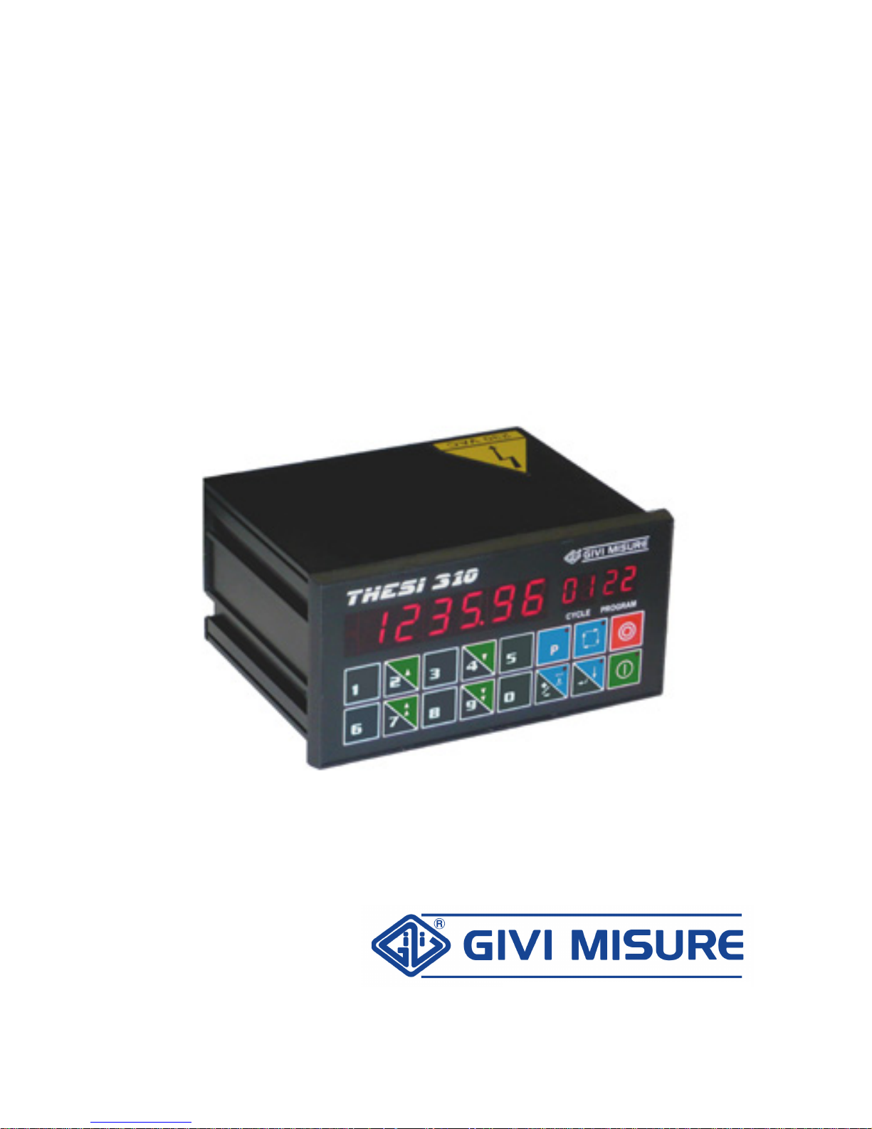
Position Controller
T
T
H
H
E
E
S
S
I
I
3
3
1
1
0
0
www.givimisure.it
USER MANUAL POSITION CONTROLLER THESI 310
MT02_A37_A_TH310_GIVI_ENG rev. E
Pag. 2/44
TABLE OF CONTENTS
PRELIMINARY REMARKS
p. 3
INSTALLATION
p. 4
DIMENSIONAL SPECIFICATIONS
p. 5
REAR PANEL - CONNECTIONS
p. 6
KEY - MESSAGES AND SIGNALING
p. 8
DATA AND PROGRAMS RETENTION
p. 10
OPERATING INSTRUCTIONS
CONFIGURATION PARAMETERS
p. 11
SETTING MACHINING PROGRAMS
p. 31
MANUAL OPERATION
p. 34
SEMI-AUTOMATIC OPERATION
p. 35
AUTOMATIC OPERATION
p. 37
INPUTS
p. 39
OUTPUTS
p. 40
ADDITIONAL INFORMATION
CONFIGURATION PARAMETERS: MEMO
p. 41
TECHNICAL CHARACTERISTICS
p. 42
WARRANTY TERMS
p. 43
USER MANUAL POSITION CONTROLLER THESI 310
MT02_A37_A_TH310_GIVI_ENG rev. E
Pag. 3/44
GIVI MISURE would like to thank you for purchasing the programmable position controller
MICROCOMPUTER
and confirms the excellent choice made.
Thanks to a powerful microcontroller, the instrument is completely programmable by
keyboard.
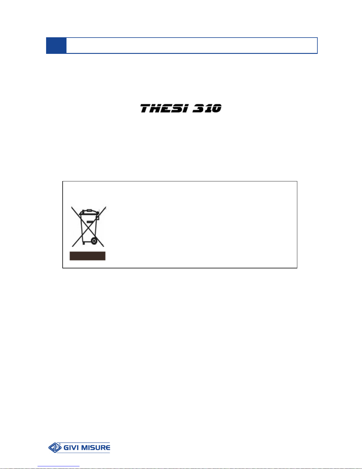
PRELIMINARY REMARKS
Disposal of waste electrical and electronic equipment (WEEE)
European Council Directive 2002/96/EC
The use of the WEEE symbol indicates that this product may not
be treated as household waste. If this product is disposed
correctly, you will help to protect the environment. For more
detailed information about the recycling of this product, please
contact your local authority, your household waste disposal
service provider or the retailer where you purchased the product.
USER MANUAL POSITION CONTROLLER THESI 310
MT02_A37_A_TH310_GIVI_ENG rev. E
Pag. 4/44
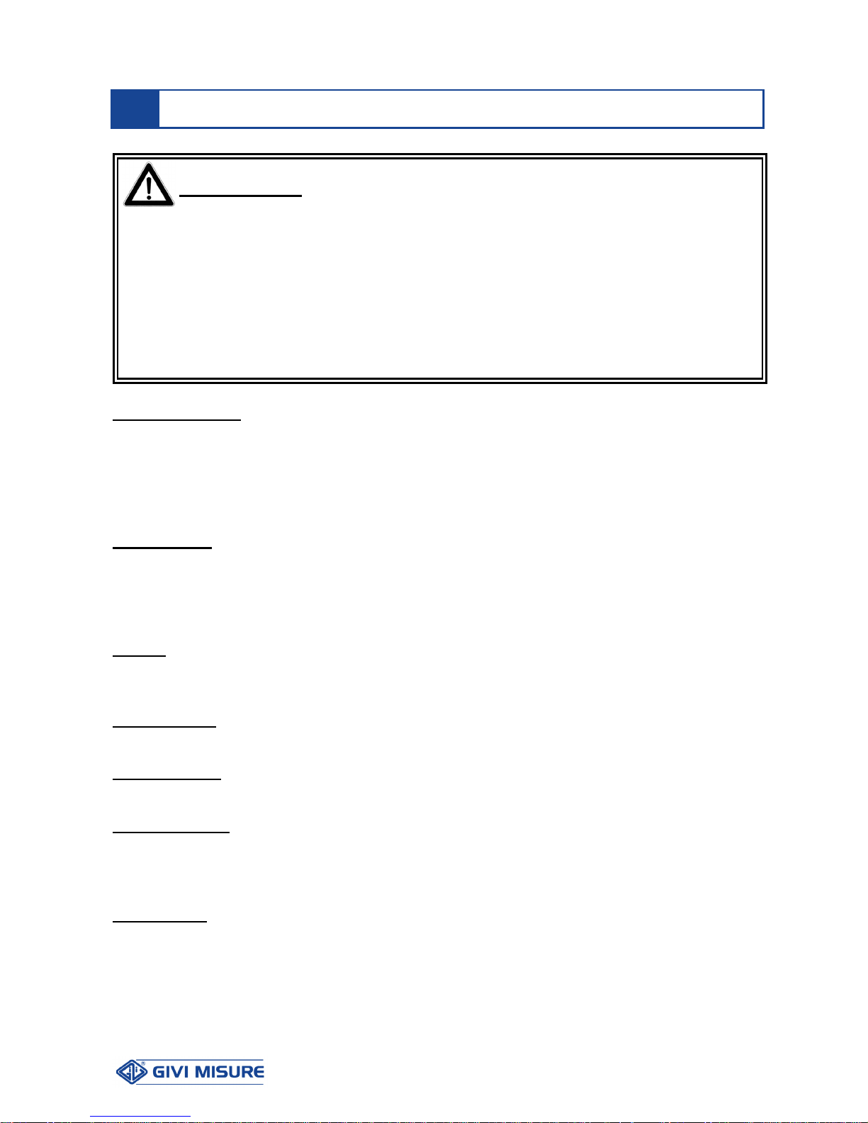
W A R N I N G
!
It is forbidden to switch on the instrument unless the machine on which it
is installed conforms to 2006/42/EC Directive.
All of the equipments connected to the instrument must have insulation
characteristics in compliance with the regulations in force.
The instrument can be installed only by specialized personnel, following
the instructions provided by the Manufacturer.
It is strictly forbidden to intervene on the instrument while it is powered.
POWER SUPPLY From 90 Vac to 230 Vac ± 10% - 50/60 Hz or, alternatively,
24 Vac ± 10% - 50/60 Hz (by means of selector). We recommend the
use of a mains power supply provided with an input filter. The power
distribution network to which the instrument is connected must be
equipped with a sectioning device in compliance with the regulations in
force, positioned closed to the instrument.
GROUNDING The instrument is connected to the ground through the power supply
terminal block. To avoid discharges, we recommend the use of a
socket with a grounding connection. In case of inadequate grounding
connections, all the accessible parts, including those apparently
protected, may generate electrical discharges.
FUSES Unplug or completely disconnect the power supply before changing
the fuses connected to the terminal block in the rear panel. Use only
delay fuses ø5x20 mm 500 mA 250 V.
PREVENTION To avoid fires or explosions, this instrument should not be used in the
presence of inflammable gases, solvents, explosives, etc.
REAR PANEL It can be removed only by specialized personnel, after disconnecting
the power supply.
INSTALLATION The measuring systems (optical scale, rotary encoder, etc.) must be
installed following the instructions provided by the Manufacturer. Start
connecting the inputs and outputs. At the end, proceed with the power
supply connection.
CATEGORY Installation category II as per Standard EN 61010-1.
INSTALLATION
USER MANUAL POSITION CONTROLLER THESI 310
MT02_A37_A_TH310_GIVI_ENG rev. E
Pag. 5/44
CLEANING The front panel can be cleaned only after disconnecting power supply,
using a moist cloth. The instrument is not protected against liquid
penetration.
DO NOT USE SOLVENTS.
MAINTENANCE Not required.
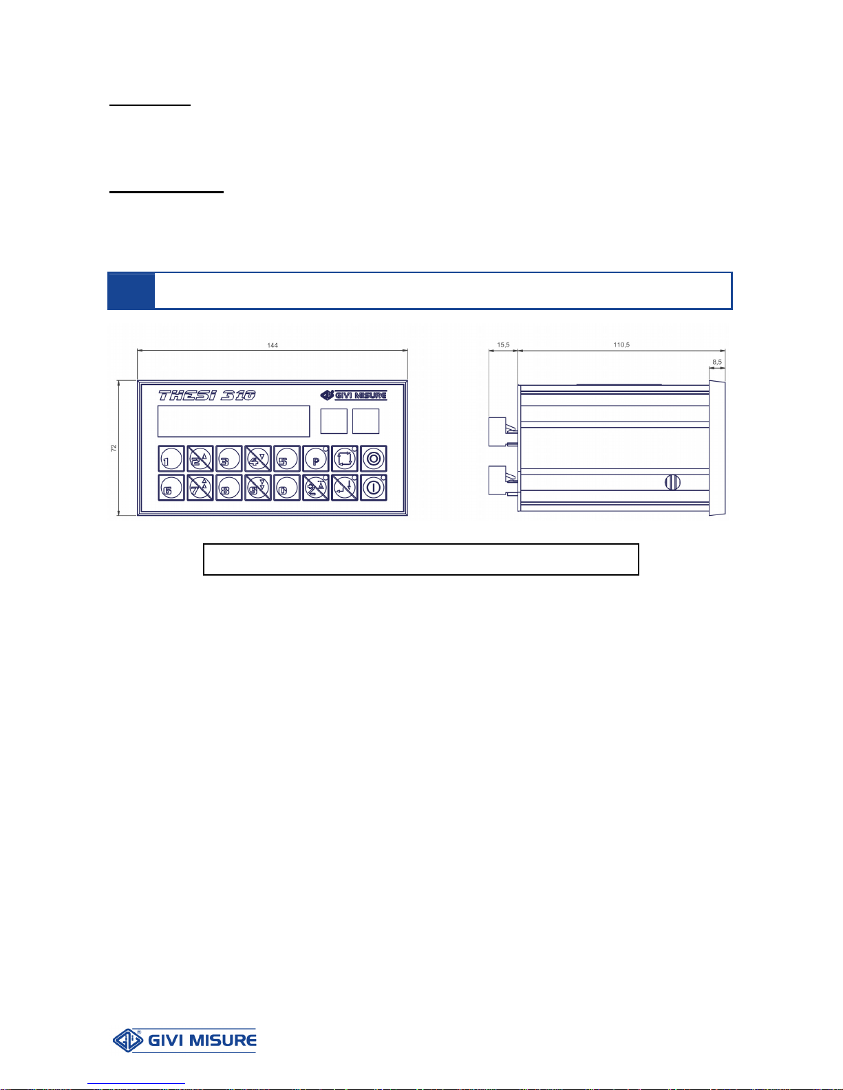
DIMENSIONAL SPECIFICATIONS
DRILLING TEMPLATE: 137.2 x 67.8 mm
USER MANUAL POSITION CONTROLLER THESI 310
MT02_A37_A_TH310_GIVI_ENG rev. E
Pag. 6/44
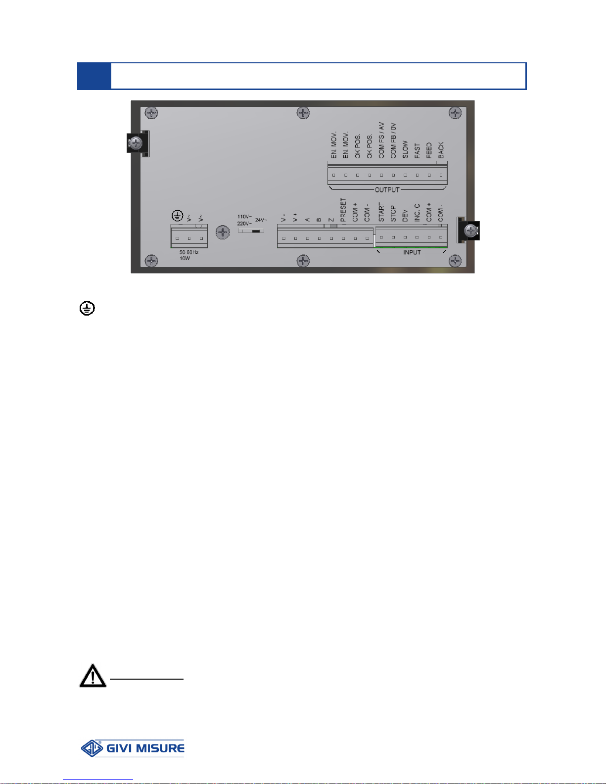
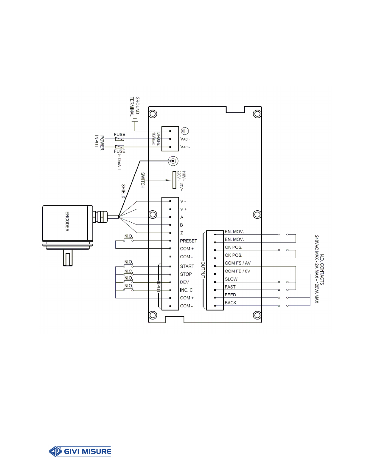
LEGEND:
= Ground connection
V ~ = Power supply from 90 Vac to 230 Vac ± 10% - 50/60 Hz
(or 24 Vac ± 10% - 50/60 Hz)
V – = Encoder power supply output (0 V)
V + = Encoder power supply output (5 V or 12 V)
A = ENCODER channel A input
B = ENCODER channel B input
Z = ENCODER channel Z input (zero reference)
PRESET = Position PRESET input
START = START input
STOP = STOP input
DEV = DEVIATION input
INC.C = INCREASE CYCLE input
COM + = Positive inputs common (12 Vdc)
COM – = Negative inputs common (0 Vdc)
EN.MOV = MOVEMENT ENABLE contact
OK.POS = OK POSITION contact
COM FS/AV = FAST/SLOW (DI) contacts common or
± 10 Vdc analog output (AN)
COM FB/0V = FEED/BACK (DI) contacts common or
0 V analog output (AN)
SLOW = SLOW contact
FAST = FAST contact
FEED = FEED contact
BACK = BACK contact
W A R N I N G !
Check the correct position of the power supply selector before powering the instrument.
REAR PANEL - CONNECTIONS
USER MANUAL POSITION CONTROLLER THESI 310
MT02_A37_A_TH310_GIVI_ENG rev. E
Pag. 7/44
CONNECTIONS

USER MANUAL POSITION CONTROLLER THESI 310
MT02_A37_A_TH310_GIVI_ENG rev. E
Pag. 8/44
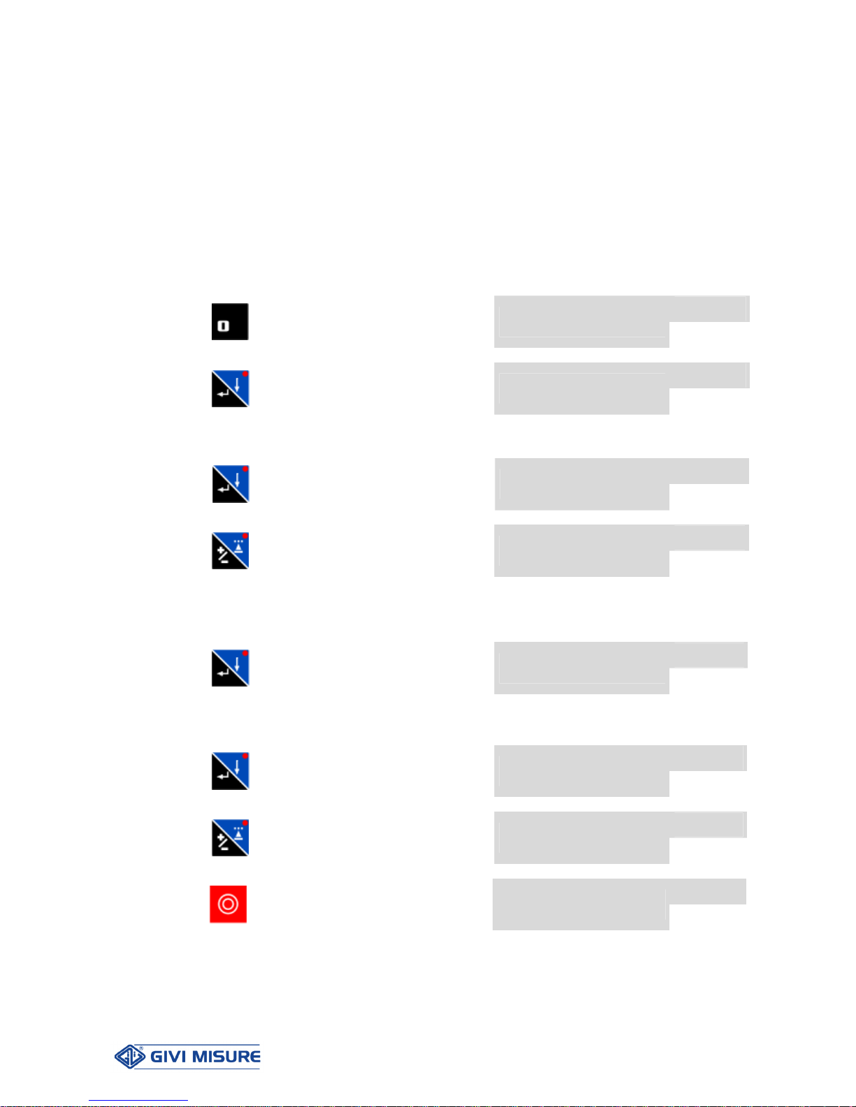
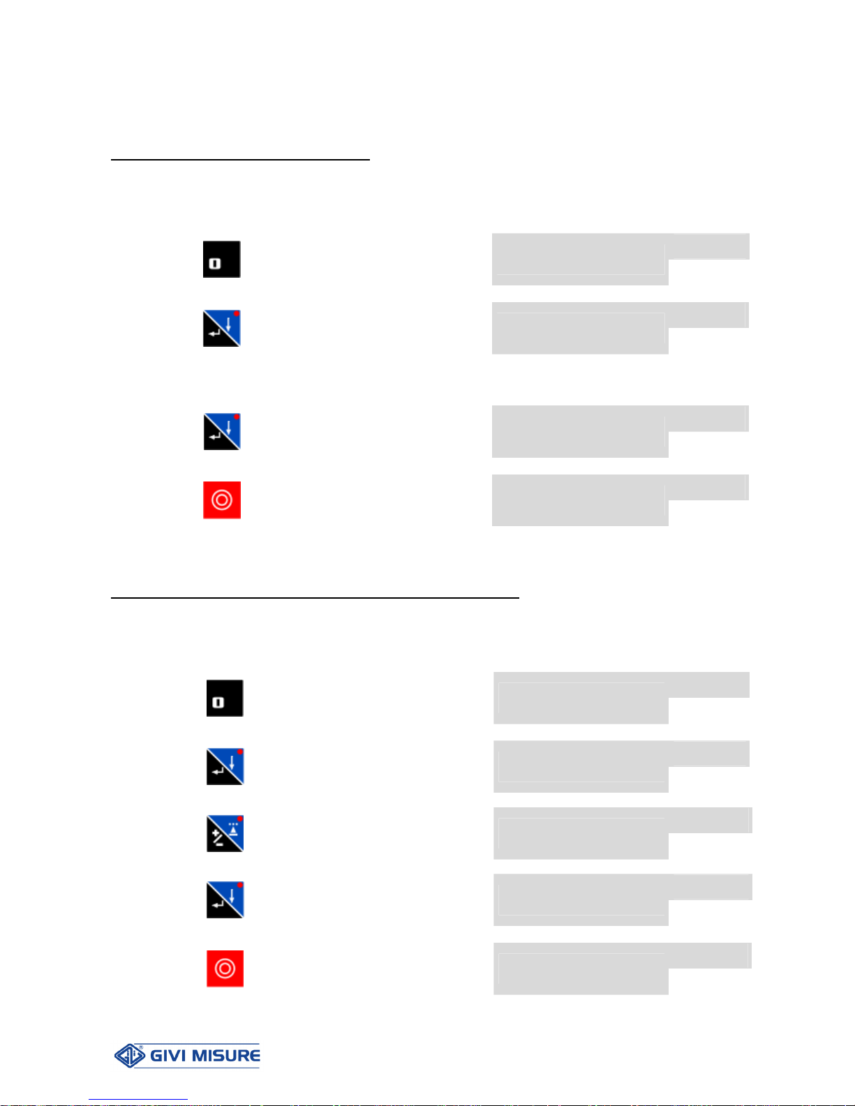
The following keys and symbols are used in this manual, with the following meaning:
….
NUMERICAL KEYS FOR DIGIT ENTRY
KEYS USED ALSO FOR SLOW FEED / BACK MOVEMENTS IN
MANUAL OPERATION
KEYS USED ALSO FOR FAST FEED / BACK MOVEMENTS IN
MANUAL OPERATION
KEY USED TO SAVE MACHINING PROGRAMS
KEY USED TO ENABLE AUTOMATIC OPERATION
KEY USED TO STOP AXIS MOVEMENT
KEY USED TO SELECT THE OPTIONS DISPLAYED
ALSO USED TO SELECT THE ALGEBRAIC SIGN AND TO ENABLE
DEVIATION
ENTER KEY, USED TO CONFIRM DATA
ALSO USED TO ENABLE SEMI-AUTOMATIC OPERATION
KEY USED TO START AXIS MOVEMENT
* FLASHING VALUE
y STEADY VALUE
KEY – MESSAGGES AND SIGNALING

USER MANUAL POSITION CONTROLLER THESI 310
MT02_A37_A_TH310_GIVI_ENG rev. E
Pag. 9/44
The instrument provides a series of visual signals to support the user during configuration
and use.
Wrong operations are signaled with the following message:
E r r o r
that temporarily appears on the display to inform the operator that the entered key is not
compatible with the current operation.
In case of “overflow” error , i.e. the number of digits displayed is greater than the
instrument counting capacity, the error is shown on the display as:
_ _ _ _ _ _
To exit this situation, enter a compatible position in the “Position Preset” parameter.
In certain situations, the error message will be accompanied by a number, indicating the
cause of the error. For example:
E r r o r 20
The list of possible errors is provided in the table below:
Error Number Description
20
Function not present
21
Axis in motion
22
Program unavailable
23
End of memory
24
Outside measuring length limits
25
Value not permitted
90
Internal malfunctioning (request Technical Assistance)
E0
Configuration Error (request Technical Assistance)

USER MANUAL POSITION CONTROLLER THESI 310
MT02_A37_A_TH310_GIVI_ENG rev. E
Pag. 10/44
When the mains power supply is disconnected, the instrument can retain in its memory all
the data and programs set. When powered off, the instrument can also store the last axis
counting position.
)
The instrument cannot consider shifts of the carriage made whenever the mains
power supply is disconnected (due to inertia, manual manoeuvres, or thermal
expansion). Whenever any of the above occurs, the position shown in the display is
unreliable; it does not represent the new position of the carriage but the one it had
prior to power disconnection.
DATA AND PROGRAMS RETENTION

USER MANUAL POSITION CONTROLLER THESI 310
MT02_A37_A_TH310_GIVI_ENG rev. E
Pag. 11/44
OPERATING INSTRUCTIONS
Some internal parameters are used for the instrument configuration.
To recall configuration, it is necessary to press the 0 key for 2 seconds, enter the
password and confirm with the ENTER key.
The desired parameter is selected with the +/- key.
Press the ENTER key to modify a parameter.
)
Access to parameters is possible only after entering a 6-digit password,
programmable by the user.
The default password set by the Manufacturer is “000000”.
)
FOR SAFETY REASONS, THE INSTRUMENT DOES NOT PROCESS ANY
PRESSED KEY, UNLESS THE STOP INPUT IS CLOSED.
The parameters currently available are:
Parameter 01 – POSITION PRESET
Parameter 02 – INVERSION OF COUNTING DIRECTION
Parameter 03 – ENCODER PULSE CORRECTION
Parameter 04 – COUNTING MODE (x1,x2,x4)
Parameter 05 – DECIMAL POINT POSITION (0,1,2,3)
Parameter 06 – AXIS RESOLUTION
Parameter 07 – SETTING OF MINIMUM MEASURING LENGTH LIMIT
Parameter 08 – SETTING OF MAXIMUM MEASURING LENGTH LIMIT
Parameter 09 – SETTING OF PRESET POSITION
Parameter 10 – SETTING OF MECHANICAL BACKLASH RECOVERY VALUE
Parameter 11 – SETTING OF SPEED CHANGE VALUE
Parameter 12 – SETTING OF NEGATIVE INERTIA VALUE
Parameter 13 – SETTING OF POSITIVE INERTIA VALUE
Parameter 14 – SETTING OF POSITIONING TOLERANCE VALUE
Parameter 15 – SETTING OF DEVIATION VALUE
Parameter 16 – SETTING OF WAITING TIME FOR DEVIATION
Parameter 17 – SETTING OF WAITING TIME FOR CHECKING POSITIONING
Parameter 18 – SELECTING “POSITION IF WITHIN TOLERANCE” OPTION
Parameter 19 – SELECTING “SPEED CHANGE WITHOUT STOPPING” OPTION
Parameter 20 – SELECTING “AUTOMATIC INERTIA CALCULATION” OPTION
Parameter 21 – SELECTING “REQUESTED POSITIONING DISPLAY” OPTION
Parameter 22 – SETTING OF SLOW MOVEMENT ± 10 V OUTPUT PERCENTAGE
Parameter 23 – SETTING OF FAST MOVEMENT ± 10 V OUTPUT PERCENTAGE
CONFIGURATION PARAMETERS
USER MANUAL POSITION CONTROLLER THESI 310
MT02_A37_A_TH310_GIVI_ENG rev. E
Pag. 12/44
Parameter 24 – MM/INCH CONVERSION
Parameter 25 – SELECTING “POSITION WITH ACC./DEC. RAMPS” OPTION
Parameter 26 – SETTING OF ACCELERATION TIME
Parameter 27 – SETTING OF DECELERATION TIME
Parameter 80 – PARAMETERS’ ACCESS PASSWORD MODIFICATION
Parameter 89 – INSTRUMENT DIAGNOSTICS
Parameter 90 – RESERVED
Example of parameter selection
P --
Press
for 2 seconds. The display will
show:
0 0 0 0 0 0*
P --
Press
if the current password is the
one set by the Manufacturer
0 0 0 0 0 0*
or enter the selected password (see parameter 80).
P 01
Confirm with
key
the display will show the value of
the first parameter, e.g.
1 2 0.0
P 02
Press
to select the desired parameter,
e.g.
d i r -
Note: in this phase, it is possible to use also keys 2 and 4 to select parameters more
easily.
P 02
Press
to confirm the selection and
enter its settings
d i r -*
Set the parameter’s configuration, following the instructions provided below.
P 02
Press
to confirm the value and go back
to parameters selection
d i r -
P 03
Press
to select another parameter, e.g.
1.0 0 0 0 0
Or press
to quit configuration and go back
to the position display
1 2 0.0
)
AT ANY TIME, IT IS POSSIBLE TO QUIT THE PARAMETERS SETTING, BY
PRESSING THE STOP KEY.
USER MANUAL POSITION CONTROLLER THESI 310
MT02_A37_A_TH310_GIVI_ENG rev. E
Pag. 13/44
All the settings for the configuration of the position controller are described below:
Parameter 01 – POSITION PRESET
The parameter is used to set the real position of the axis.
Example of value setting = 200.0 mm
P 01
Press
to select the parameter
(see PARAM. SELECTION)
1 2 0.0
P 01
Press
to confirm the selection and
enter its settings
0 0 0 0 0.0*
Enter the desired value and align it to the decimal point displayed.
P 01
Press
to confirm the value and go back
to parameters selection
2 0 0.0
Press
to quit configuration and go back
to the position display
2 0 0.0
Parameter 02 – INVERSION OF COUNTING DIRECTION
With this parameter it is possible to invert the counting direction of the axis.
Example: inverting counting direction
P 02
Press
to select the parameter
(see PARAM. SELECTION)
d i r -
P 02
Press
to confirm the selection and
enter its settings
d i r -*
P 02
Press
to invert the counting direction
- d i r *
P 02
Press
to confirm and go back to
parameters selection
- d i r
Press
to quit configuration and go back
to the position display
2 0 0.0

USER MANUAL POSITION CONTROLLER THESI 310
MT02_A37_A_TH310_GIVI_ENG rev. E
Pag. 14/44
Parameter 03 – ENCODER PULSE CORRECTION
The correction factor CF is entered by the operator to adapt the machine linear shifting to
the number of encoder pulses (PPR).
For instance, in a machine with linear shifting correlated to the screw pitch, the correction
factor CF is calculated by the operator according to the formula:
SCREW PITCH (mm)
CF = -------------------------------------- (RIS * PPR * CNT)
Where: RIS = axis resolution (see parameter 06)
PPR = encoder pulses per revolution
CNT = counting mode (see parameter 04)
Suppose we have a 100 PPR encoder, a 0.01 mm resolution and a x4 counting mode.
Example A with 4 mm screw pitch, example B with 5 mm screw pitch:
in case A: CF = 4 / (0.01 * 100 * 4) = 1.00000
in case B: CF = 5 / (0.01 * 100 * 4) = 1.25000
To compensate shifting, a CF value has to be manually entered.
Example: CF value setting = 1.25000
P 03
Press
to select the parameter
(see PARAM. SELECTION)
1.0 0 0 0 0
P 03
Press
to confirm the selection and
enter its settings
0.0 0 0 0 0*
Enter the desired value and align it to the decimal point displayed.
P 03
Press
to confirm the value and go back
to parameters selection
1.2 5 0 0 0
Press
to quit configuration and go back
to the position display
2 0 0.0
 Loading...