

Page 1

fluid
gimbal head
Page 2

Page 3

fluid
gimbal head
Page 4
2 3
Instructions/Istruzioni/Gebrauchsanweisung/Mode d’emploi/Instrucciones
1
1
1
3
2
2
30°
D
A
A
B
C
Page 5
5
6
4
使用说明/사용설명서/使用説明書
7
1
2
1
2
A
E
F
H
Page 6

English
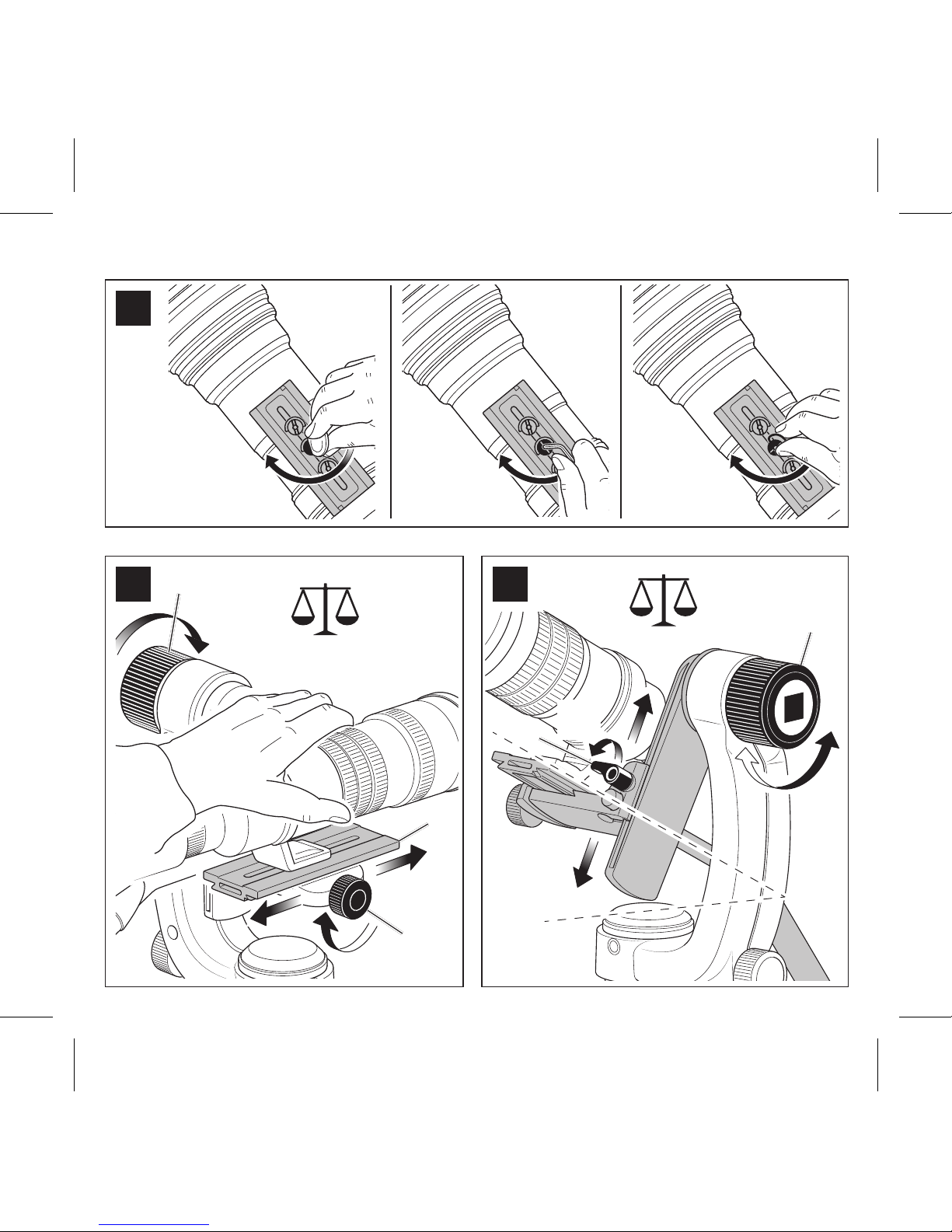
FIG. 1 – How to mount the lens on the plate
FIG. 2 – Find the horizontal balance point
- Insert the lens and plate from above.
- Holding the lens securely in one hand, unlock the tilt Brake knob “A” with
the other hand.
- Put the Lens in horizontal direction and check if it remains horizontal or if
it starts to move.
- If the lens doesn’t remain in horizontal position, slide the plate “B” forward /
backward until it the balanced point is found. Lock the plate with knob “C”.
FIG. 3 – Find the vertical balance point
- T
his setting has to be done only after previous operation (horizontal balance).
- With the Tilt Brake knob released, Tilt the lens about 30°- 45° towards the
sky and check how the lens moves.
- If the lens continues to tilt further towards the sky, you need to lower the
position of the lens unlock the vertical adjustment knob “D”, slide down the
lens support, lock “D”, and tilt the lens again.
- If the lens tilts back towards the ground, you need to raise the position of
the lens.
- Repeat until you find the vertical balance point where the lens stays in
position at any tilt angle.
Page 7

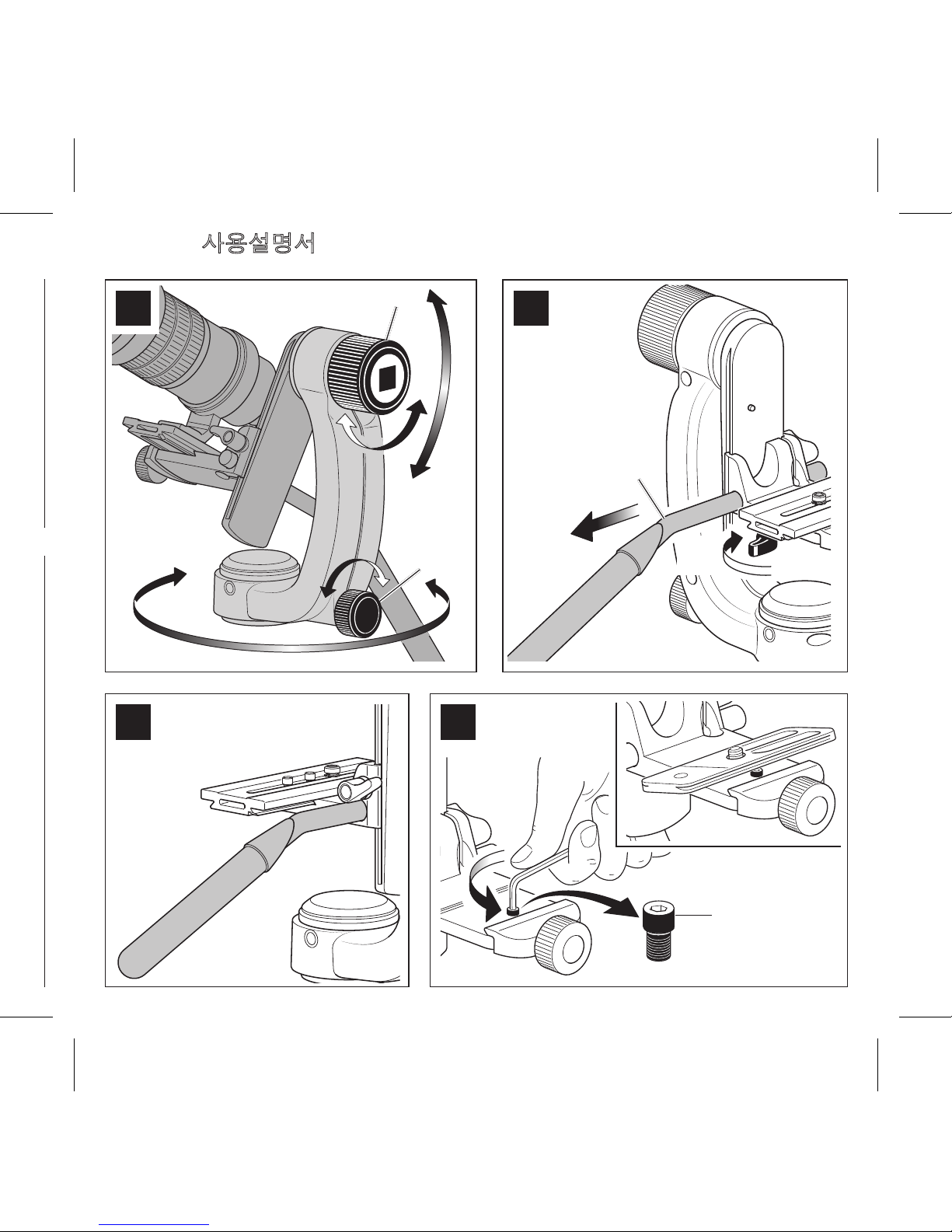
FIG. 4 – Use
Tilt Brake knob “A”
Pan Brake knob “E”
Note
Pan and tilt axis have an appropriate drag level when rotating at low speed
during video recording or precise target chase.
Besides pan axis has a low friction when panning at high speed: your tripod
stay in position.
FIG. 5-6 – Direction and pan bar
The head can be used in 2 directions. In both directions, it can be used with
or without the pan bar “F”.
The pan bar length can be adjusted by locking the bar at the desired position.
FIG. 7 – Usage with other brand plates
The head accommodates some plates with similar dimensions. Test your
plate by mounting it on the quick release adaptor. If the safety pin “H” blocks
the mounting of the plate, or prevents the sliding of the plate, remove the
safety pin, but take care you haven't a safety pin stop anymore!
In addition to reading these instructions, it is also important to read the
general instructions printed on the warranty card packed with your product.
Page 8

Italiano
FIG. 1 - Come montare l'obiettivo sulla piastra
FIG. 2 - Trovare il punto di equilibrio orizzontale
- Inserire la lente e la piastra dall'alto.
- Tenendo la lente saldamente con una mano, sbloccare il freno tilt manopola
“A” con l'altra mano.
- Posizionare la lente in direzione orizzontale e verificare se rimane orizzontale
o se inizia a muoversi.
- Se la lente non rimane in posizione orizzontale, far scorrere la piastra “B” in
avanti / indietro fino a trovare il punto di equilibrio. Bloccare la piastra con
la manopola “C”.
FIG. 3 - Trovare il punto di equilibrio verticale
- Questa operazione deve essere fatta solo dopo la precedente (equilibrio
orizzontale).
- Con la manopola del freno del tilt rilasciato, inclinare la lente di circa 30 ° 45 ° verso l’alto e controllare come si muove l’obiettivo.
- Se la lente continua ad inclinarsi ulteriormente verso l’alto, è necessario
abbassare la posizione della lente e sbloccare la manopola di regolazione
verticale “D”, far scorrere verso il basso il supporto della lente, bloccare la
manopola “D” ed inclinare di nuovo la lente.
- Se la lente si inclina verso il basso, è necessario alzare la posizione della
lente.
- Ripetere l'operazione fino a trovare il punto di equilibrio verticale nel quale la
lente rimane in posizione in qualsiasi angolo di inclinazione.
Page 9

FIG. 4 - Uso
“A”: manopola freno Tilt
“E”: manopola freno Pan
Nota: I movimenti panoramico e tilt hanno un livello di fluidità tale da consentire un’ottimale qualità della ripresa anche con spostamenti ridotti della lente.
La testa è dotata di sistema di frizionamento automatico sull’asse panoramico, che garantisce la stabilità del treppiede anche in caso di movimenti
rapidi della lente.
FIG. 5-6 – Pozione della leva di comando
La testa può essere utilizzata in 2 direzioni. In entrambe le direzioni, può essere utilizzata con o senza la leva di comando “F”.
La lunghezza della leva può essere regolata bloccando la leva nella posizione
desiderata.
FIG. 7 - Uso della testa con altre piastre
La testa può ospitare alcuni tipi di piastra con dimensioni simili.
Fissare la piastra montandola nella testa.
Se il perno di sicurezza “H” non permette il montaggio della piastra o ne impedisce lo scorrimento, deve essere rimosso: in questo caso fate attenzione
perché la testa sarà priva di perno di sicurezza.
Oltre a leggere queste istruzioni, è importante anche consultare le istruzioni
generali riportate sulla cartolina di garanzia fornita insieme al prodotto.
Page 10

Deutsch
ABB. 1 – Befestigung des Objektivs an der Platte
ABB. 2 – Einstellung des horizontalen Gleichgewichtspunkts
- Objektiv und Platte von oben einsetzen.
- Objektiv mit einer Hand festhalten und mit der anderen Hand den
Verriegelungsknopf für die Neigung “A” lösen.
- Das Objektiv in horizontale Lage bringen und überprüfen, ob es dort bleibt
oder sich bewegt.
- Bleibt das Objektiv nicht in horizontaler Lage, die Platte “B” vor- bzw.
zurückschieben, bis der Gleichgewichtspunkt gefunden ist. Die Platte mit
Knopf “C” arretieren.
ABB. 3 – Einstellung des vertikalen Gleichgewichtspunkts
- Diese Einstellung ist erst nach der Einstellung des horizontalen
Gleichgewichtspunktes vorzunehmen.
- Den Verriegelungsknopf für die Neigung lösen. Das Objektiv circa 30 °- 45 °
nach oben bewegen und überprüfen, wie es sich verhält.
- Kippt das Objektiv nach oben, muss eine tiefere Position eingestellt
werden. Dazu den Knopf für die vertikale Ausrichtung “D” lösen, die
Objektivhalterung nach unten schieben, Knopf “D” arretieren und das
Verhalten des Objektivs erneut beobachten.
- Kippt das Objektiv nach unten, muss eine höhere Position eingestellt
werden.
- Diesen Vorgang wiederholen, bis der vertikale Gleichgewichtspunkt
gefunden ist, bei dem das Objektiv unabhängig vom Neigewinkel in Position
bleibt.
Page 11

ABB. 4 – Verwendung
Verriegelungsknopf für die Neigung “A”
Verriegelungsknopf für die Schwenkbewegung “E”
Hinweis: Für die präzise Verfolgung bewegter Objekte bei Videoaufnahmen
verfügen die Schwenk- und Neigeachse über einen angemessenen
Widerstand.
Die Schwenkachse bietet eine geringe Friktion für schnelle
Schwenkbewegungen: Ihr Stativ bleibt in Position.
ABB. 5-6 – Richtung und Schwenkarm
Der Kopf kann in zwei Richtungen verwendet werden. In beiden Fällen kann
er mit oder ohne Schwenkarm “F” eingesetzt werden.
Die Länge des Schwenkarms ist einstellbar. Er wird einfach in der
gewünschten Länge arretiert.
ABB. 7 – Verwendung mit Platten anderer Hersteller
Der Kopf eignet sich für einige andere Platten mit ähnlichen Abmessungen.
Testen Sie Ihre Platte, indem Sie diese auf dem Schnellwechseladapter
befestigen. Verhindert der Sicherungspin “H” die Befestigung oder das
Verschieben der Platte, entfernen Sie den Sicherungspin. Beachten Sie dann
aber, dass diese Sicherung nicht mehr vorhanden ist.
Bitte lesen Sie neben dieser Anleitung auch die allgemeinen Hinweise auf
dem Garantieschein, der Ihrem Produkt beiliegt.
Page 12

Français
FIG. 1 – Comment fixer le plateau sur l’objectif
FIG. 2 – Trouver le point d’équilibre horizontal
- Insérer l’objectif avec le plateau par le haut.
- En maintenant l’objectif avec une main, utiliser l’autre main pour déverrouiller
la poignée de verrouillage du mouvement de bascule “A”.
- Placer l’objectif en position horizontale puis vérifier s’il reste en position
ou s’il bouge.
- Si l’objectif ne reste pas en position horizontale, faire coulisser le plateau
“B” d’avant en arrière jusqu’à trouver le point d’équilibre. Verrouiller le
plateau avec la poignée “C”.
FIG. 3 – Trouver le point d’équilibre vertical
- Cette étape est à réaliser uniquement après avoir effectué l’étape
précédente (balance horizontale).
- Déverrouiller la poignée “A”, soulever l’objectif vers le ciel avec un angle de
30-45° puis vérifier les mouvements de l’objectif.
- Si l’objectif pointe davantage vers le haut, il faut reculer la position de
l’objectif : pour cela déverrouiller la poignée “D”, faire glisser le plateau vers
le bas, verrouiller la poignée “D” puis faire pencher l’objectif à nouveau.
- Si l’objectif penche en direction du sol, il faut avancer la position de
l’objectif.
- Répéter l’opération jusqu’à trouver le point d’équilibre vertical : l’objectif
reste en position, peu importe l’angle d’orientation.
Page 13

FIG. 4 – Utilisation
Poignée de verrouillage du mouvement de bascule “A”
Poignée de verrouillage du mouvement panoramique “B”
Remarques: L’axe panoramique et l’axe de bascule offrent des mouvements
d’une fluidité remarquable pour les rotations lentes lors de réalisations de
vidéos ou le suivi de cibles précises.
L’axe panoramique est équipé d’une friction basse pour les mouvements très
rapides, le trépied reste stable.
FIG. 5-6 – Direction et poignée de guidage
La rotule peut être utilisée dans deux directions. Dans les deux cas, elle peut
être utilisée avec ou sans la poignée de guidage “F”.
Il est possible d’ajuster la longueur de la poignée de guidage en verrouillant
la poignée à la longueur souhaitée.
FIG. 7 – Utilisation avec des plateaux d’autres marques
La rotule est compatible avec certains plateaux de dimensions similaires.
Tester le plateau en le fixant sur l’adaptateur plateau rapide. Si la vis de
sécurité “H” empêche la fixation ou le coulissement du plateau, il faut la
retirer. Attention, utiliser le matériel avec une précaution supplémentaire
après avoir retiré la vis de sécurité !
Il est également important de lire les informations générales présente sur la
carte de garantie fournie avec le produit.
Page 14

Español
FIG. 1 – Cómo montar el objetivo en la zapata
FIG. 2 – Cómo encontrar el punto de equilibrio horizontal
- Coloque el objetivo y la zapata desde arriba.
- Mientras sostiene con seguridad el objetivo con una mano, desbloquee el
control de inclinación (tilt) “A” con la otra mano.
- Ponga el objetivo en dirección horizontal y compruebe si se mantiene horizontal o si empieza a moverse.
- Si el objetivo no permanece en posición horizontal, deslice la zapata “B”
adelante / atrás hasta encontrar el punto de equilibro. Bloquee la zapata
con el control “C”.
FIG. 3 – Cómo encontrar el punto de equilibrio vertical
- Este ajuste debe realizarse únicamente tras el anterior (equilibrio horizontal).
- Con el control de inclinación (Tilt) liberado, incline el objetivo entre 30°- 45°
orientado al cielo y compruebe como se mueve el objetivo.
- Si el objetivo continúa inclinándose todavía más hacia el cielo, será necesario bajar la posición del objetivo y desbloquear el ajuste vertical “D”, deslizar
el soporte del objetivo, bloquear “D”, e inclinar el objetivo de nuevo.
- Si el objetivo se inclina hacia el suelo, será necesario levantar la posición
del objetivo.
- Repetir hasta encontrar el punto de equilibrio vertical, en el cual el objetivo
permanezca en posición en cualquier ángulo de inclinación.
Page 15

FIG. 4 – Uso
Control de inclinación (Tilt) “A”
Control de paneo (Pan) “E”
Nota: Los ejes de paneo (pan) e inclinación (tilt) incorporan el nivel de arrastre apropiado al realizar el movimiento de rotación a baja velocidad durante la
grabación de vídeo o un seguimiento preciso del sujeto.
Además, el eje de paneo (pan) posee una baja fricción al realizar el movimiento de paneo a alta velocidad: el trípode se mantiene en su posición.
FIG. 5-6 – Dirección y barra de paneo
La rótula se puede usar en 2 direcciones. En ambas direcciones, se puede
usar con o sin la barra de paneo “F”.
La longitud de la barra de paneo se puede ajustar bloqueando la barra en la
posición deseada.
FIG. 7 – Uso con zapatas de otras marcas
La rótula puede alojar diversas zapatas con dimensiones similares. Compruebe su zapata montándola en el adaptador de liberación rápida. Si el pin de
seguridad “H” bloquea el montaje de la zapata, o evita su deslizamiento,
extraiga el pin de seguridad, pero tenga cuidado ya que no dispondrá del
pin de seguridad.
Además de leer estas instrucciones específicas, es también importante leer
las instrucciones generales impresas en la tarjeta de garantía incluida con
su producto.
Page 16

简体中文
图1 - 如何将镜头安装到快装板上
图2 - 找到水平方向平衡点
-从上方插入镜头和快装板。
-用一只手牢牢握住镜头,另一只手打开俯仰制动旋钮“A”。
-将镜头水平放置,检查镜头是否保持水平或者开始移动。
-如果镜头未处于水平位置,向前/向后滑动快装板“B”,直至找到平衡
点。 用旋钮“C”锁定快装板。
图3 - 找到垂直方向平衡点
-在完成上一步操作后(水平方向平衡)才可进行此设置
-松开俯仰制动旋钮,将镜头向天空倾斜约30° - 45°,并检查镜头如
何移动
-如果将镜头继续向天空倾斜,您需要降低镜头的位置,松开垂直调整旋
钮“D”,向下滑动镜头支架,锁定旋钮“D”,然后再次倾斜镜头。
-如果将镜头向地面倾斜,您需要提高镜头的位置。
-重复此操作,直至找到垂直方向平衡点。在此平衡点,镜头能够在任何
倾斜角度保持在原位。
图4 - 使用
俯仰制动旋钮“A”
水平制动旋钮“E”
注意
在视频记录或精确目标追踪期间以低速转动时,水平和俯仰轴拥有适当
阻尼。
此外,水平轴在高速平移时具有低摩擦力:您的三脚架保持在原位。
Page 17

图5-图6 – 方向和水平杆
云台可在2个方向上使用。 在两个方向上,可使用或不使用水平杆“F”。
可通过将水平杆锁定在所需位置来调节水平杆长度。
图7 – 与其他品牌的快装板一起使用
此云台可与一些尺寸相似的快装板兼容。将快装板安装在快装板适配器上
来进行测试。 如果安全销“H”妨碍快装板的安装,或阻止快装板滑动,
则可将安全销取下。但请注意,您没有安全销可用来止位了!除了阅读这
些说明之外,阅读产品印制在随附保修卡上的一般说明也很重要
Page 18

그림.1 – 플레이트에 렌즈를 마운트하는 방법
그림.2 – 수평 밸런스 지점 찾기
위에서 렌즈와 플레이트를 삽입합니다.
한 손으로 렌즈를 안전하게 잡은 뒤 틸트 브레이크 잠금 장치 “A”를 다른
손으로 잠금 해제 합니다.
렌즈를 수평 방향으로 설치한 뒤 수평방향으로 머물러 있는지
움직이는지 확인합니다.
만약 렌즈가 수평방향으로 머물러 있지 않을 경우 균형이 맞도록 “B”
슬라이드를 앞뒤로 움직여 수평 위치를 맞춰 줍니다. 이 후 “C” 잠금
장치로 플레이트를 고정합니다.
그림.3 – 수직 밸런스 지점 찾기
수직 밸런스 지점은 수평 밸런스 지점 찾기를 완료한 이후에만
가능합니다.
틸트 브레이크 잠금 장치를 푼 뒤 렌즈를 위로 30°- 45° 기울이고
렌즈의 움직임을 확인합니다.
만약 렌즈가 위쪽 방향으로 더 기울어 진다면 수직 조절 잠금 장치 “D”를
풀어주어 렌즈 서포트를 아래로 내려 위치를 낮춰 주고 잠금 장치 “D”를
이용하여 잠금 뒤 렌즈를 다시 기울여 줍니다.
만약 렌즈가 뒤쪽으로 기울어 진다면 렌즈의 위치를 다시 약간
높여줍니다.
어떠한 각도에서도 렌즈가 멈추어 있는 위치를 찾기 위해서 위 과정을
반복합니다.
한국어
Page 19

그림.4 – 사용방법
틸트 브레이크 잠금 장치 “A”
팬 브레이크 잠금 장치 “B”
비고
비디오 촬영 및 특정 피사체의 정확한 타겟 촬영 중 저속 회전 시 팬과
틸트 축은 적절한 드래그 레벨을 갖습니다.
팬 축은 고속으로 회선할 때 낮은 프릭션을 갖습니다: 삼각대의
움직임은 고정일 경우
그림.5-6 – 방향 및 팬 바
헤드는 두 방향으로 사용할 수 있습니다. 두 방향 모두에서 팬 바 "F"의
사용 여부와 상관없이 사용이 가능합니다.
팬 바 길이는 바를 원하는 위치에 고정하여 조정할 수 있습니다.
그림.7 – 다른 브랜드의 플레이트를 사용하는 방법
헤드에는 비슷한 크기의 플레이트를 사용할 수 있습니다.
퀵 릴리즈 어댑터에 마운트하여 플레이트의 사용이 가능한지
확인합니다.
안전 핀 "H"가 판의 장착을 방해하거나 판의 미끄러짐을 방지하는 경우,
안전핀을 제거합니다. 더 이상 안전핀 정지가 없음에 주의 하시기
바랍니다!
이 지침사항 이외에 제품과 동봉되는 워런티 카드에 있는 일반 지침을
읽는 것 역시 중요합니다.
Page 20

日本語
図1 – プレートへのレンズの取り付け方法
図2 – 前後バランス位置を見つける
- レンズが装着されたプレートを上方向から挿入します。
- 片手でレンズを確実に持った状態で、もう一方の手でティルトロック”A”を
解除します。
- レンズを水平の状態にし、そのまま水平を維持するか動き出してしまうか
を確 認します。
- レンズが水平位置を維持しない場合、バランス位置が見つかるまでプレー
ト”B”を前後にスライドします。ノブ”C”でプレートをロックします。
図3 – 垂直バランス位置を見つける
- このセッティングは、前の手順(前後バランス)の後に行わなければなり
ません。
- ティルトロックを解除した状態で、レンズを空に向かって30-45度ティルト
させ、レンズがどう動くか確認します。
- レンズが空の方向に更にティルトしてしまう場合は、レンズの位置を下げ
る必要があります。垂直調整ノブ”D”を解除し、レンズが載っている土台を
下にスライドし、再度レンズを空の方向にティルトします。
- レンズが地面の方向にティルトしてしまう場合は、レンズの位置を上げる
必要があります。
- レンズがティルトした位置を維持した垂直バランス位置が見つかるまで
繰り返します。
Page 21

図4 – 使用
ティルトロックノブ ” A ”
パンロックノブ”E”
メモ
パン軸・ティルト軸の動きは、動画撮影や被写体を正確に追うような低速の
動きに適したドラッグレベルに設定されています。
また、パン軸は高速に動かした場合に三脚まで動いてしまわないよう、低フ
リクションに切り替 わります。
図5-6 – 使用方向とパンバー
本雲台は2つの方向で使用できます。どちらの方向でも、パンバー”F”を取り
付けての使用、取り外しての使用が可能です。
パンバーの長さは、お好みの位置にパンバーをロックすることで調整でき
ます。
図7-他社プレートの使用について
クイックリリースアダプターは、同様の外寸のプレートであれば使えるもの
もあります。クイックリリースアダプター に取り付けてご自身で お試しくださ
い。セーフティーピンがプレート取り付けやプレートスライドの邪魔になる
のであれば、セーフティーピンを一度外してください。
この使用説明書のほかに、別紙の一般情報もご一読ください。
Page 22

Page 23

Page 24

gitzo.com
fluid
gimbal head
1108130 - 03/2017
 Loading...