

Page 1

Page 2

Page 3

Page 4
1 2
3
Instructions/Istruzioni/Gebrauchsanweisung/Mode d’emploi/Instrucciones
3
1
2
1
2
Page 5
4
5
使用说明/사용설명서/使用説明書
1
3
1
2
3
2
5
6
4
Page 6
6
7
1
2
E
A
A
C
A
Page 7
8
9 10
2
1
1
1
2
2
B
C
C
E
P
L
Page 8
11
1312
2
1
3
4
Page 9
14
5
6
7
8
9
2
1
3
Page 10

15
1
2
3
4
Page 11
16
Page 12

English
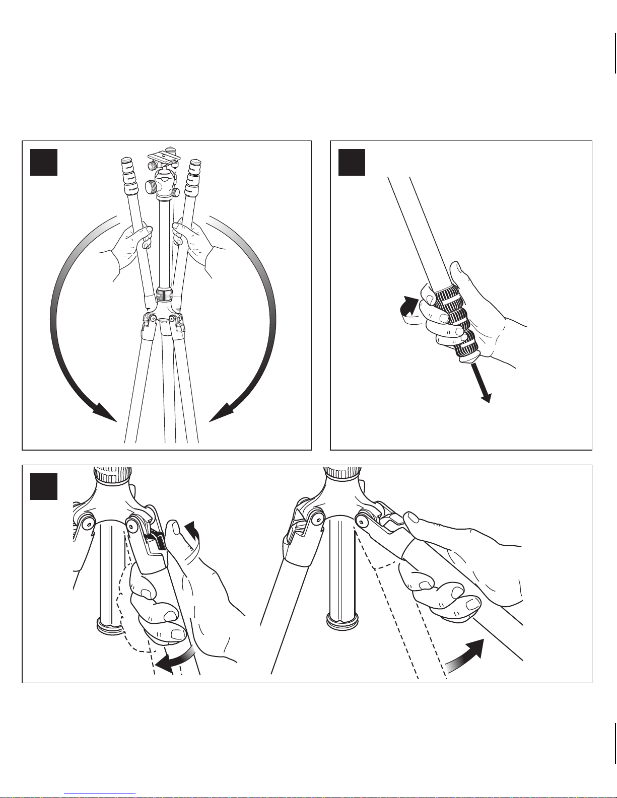
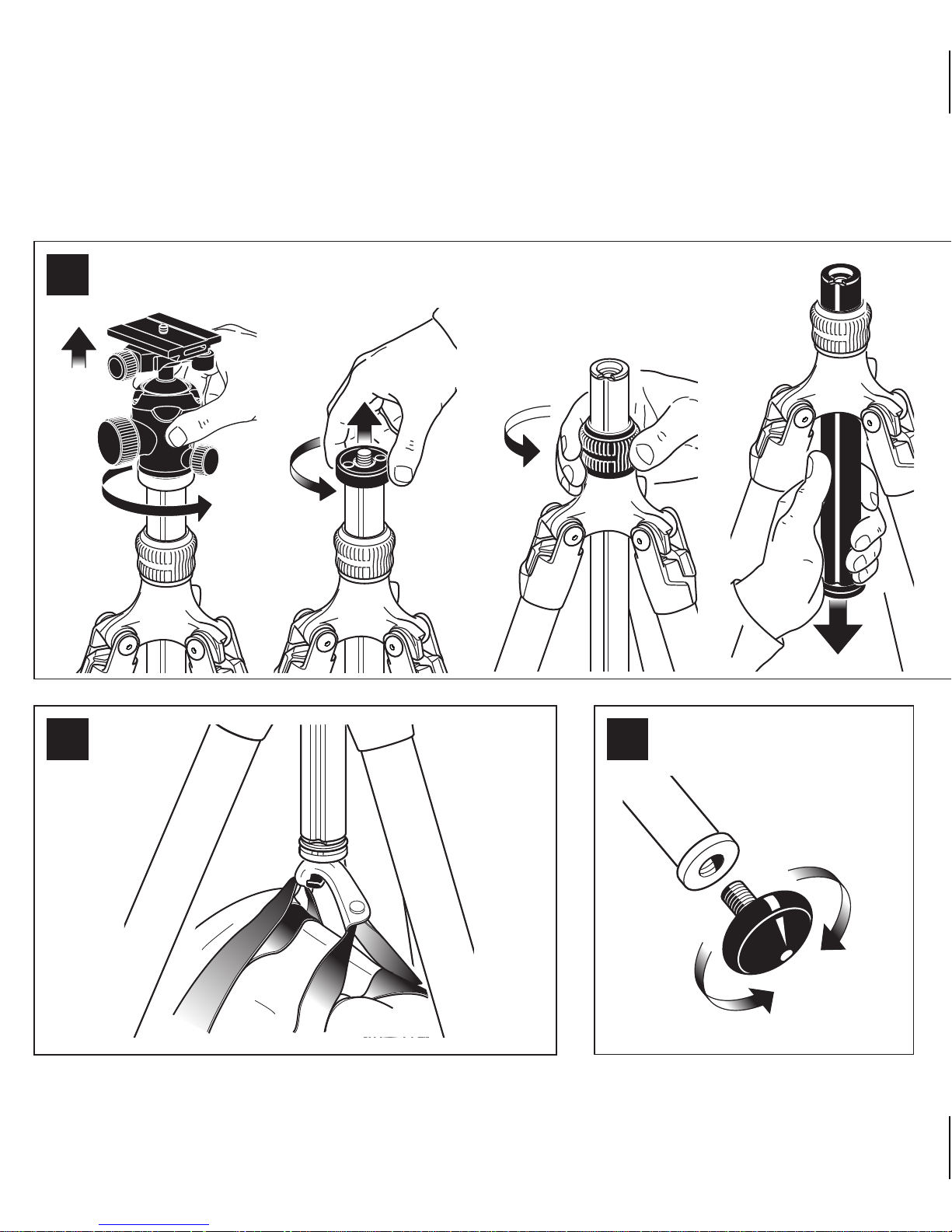
FIG. 1 – Set up
FIG. 2 – Extending the tripod legs
Turn all the twist locks of each leg 1/4 of a turn at the same time, then pull the
leg down and tighten the twists individually.
FIG. 3 – Leg angle adjustment
To change the leg angle to the lower position, close the leg slightly by folding
it towards the centre column, push the angle selector to the right, and lift
the leg.
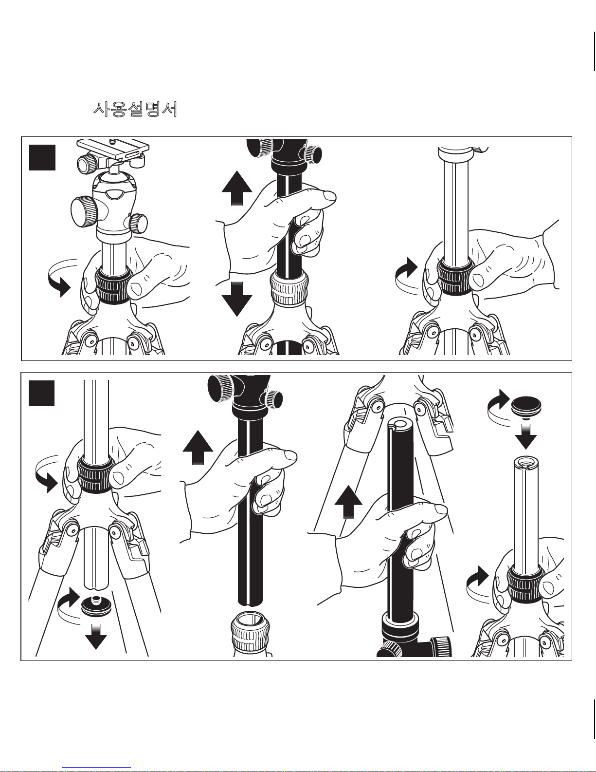
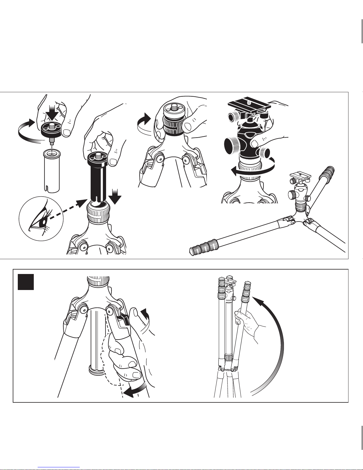
FIG. 4 – Raising and lowering column
FIG. 5 – Reversing column
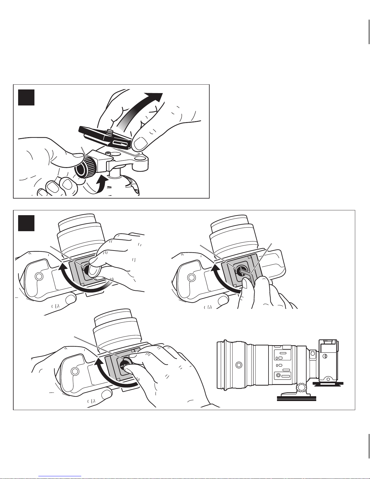
FIG. 6 – How to remove the camera plate
Hold the camera plate, loosen screw “C” as shown in the diagram, and lift the
plate out of the quick release adaptor.
FIG. 7 – How to mount the camera on the plate
To tighten the plate “A”, you can use
- a coin
- hex key “E”
- the screw’s flip ring
The plate can be mounted on the camera/lens in different directions.
Page 13

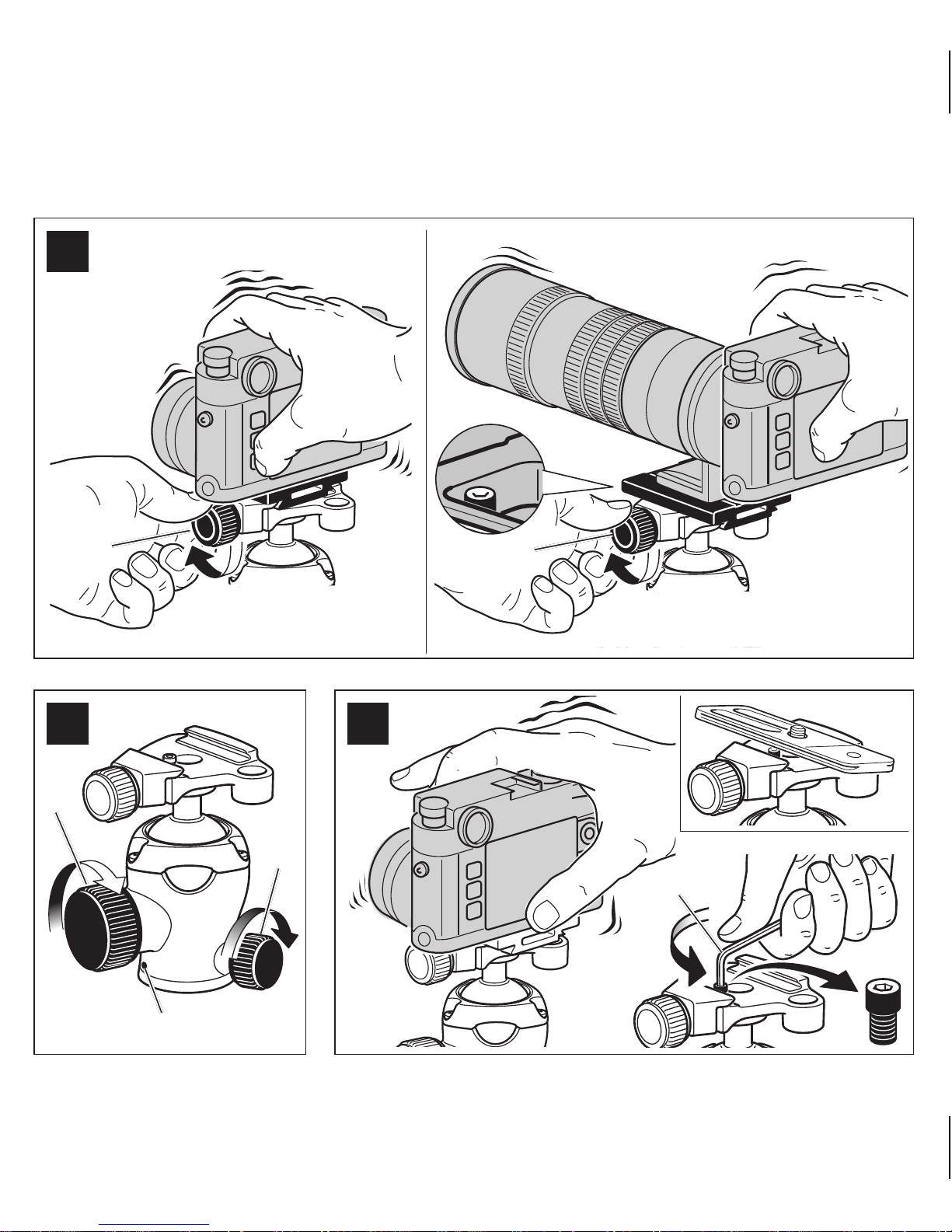
FIG. 8 – How to mount the camera on the head
Insert the camera and plate from above. Tighten knob “C” to lock the camera
securely in place. The quick release adaptor allows the sliding of the plate
when the locking lever is not fully locked, and includes a safety pin that
prevents accidental fallings of the camera.
FIG. 9 – Locking / friction control
B Ball movement lock
L Pan movement lock
P Index for pan
FIG. 10 – Usage with other brand plates
The quick release adaptor is also designed to accommodate some plates
with similar dimensions. Test your plate by mounting it on the quick release
adaptor.
If the safety pin blocks the mounting of the plate, or prevents the sliding of the
plate, remove the safety pin.
FIG. 11 – Shooting from ground level
The tripod is supplied with a short column which is useful to get the camera
closer to the ground when the leg angle is set to the lower position.
FIG. 12 – Hook
It allows you to hang a stabilising weight (e.g. A full camera bag or a sand/
water bag) on the bottom of the tripod.
Page 14

FIG. 13 – Replaceable foot
In case the foot becomes worn, it can be replaced easily with a new foot
(available as a spare part).
FIG. 14 – Closing the tripod
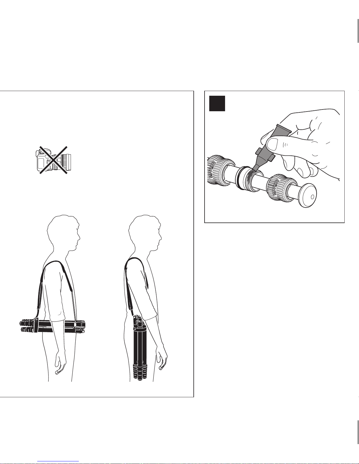
FIG. 15 – Shoulder strap
When using the shoulder strap, always remove the camera from the
tripod.
FIG. 16 – Maintenance
The internal thread of the leg locks can be cleaned and greased to perform
optimally. Turn the twist lock until the thread is exposed, and remove any
dust or sand with a cloth. Apply a small amount of grease (sold separately:
GSGREASE02) onto the thread, and turn the twist lock until it is locked.
In addition to reading these instructions, it is also important to read the
general instructions printed on the warranty card packed with your product.
Page 15

Italiano
FIG. 1 – Preparazione
FIG. 2 – Allungamento delle gambe del treppiedi
Ruotare tutti insieme i collari di bloccaggio di ogni gamba di 1/4 di giro in
senso antiorario, quindi abbassare le sezioni e serrare i singoli collari nella
posizione desiderata.
FIG. 3 – Regolazione dell’angolazione delle gambe
Per modificare l'angolo della gamba nella posizione inferiore, chiudere
la gamba leggermente piegandola verso la colonna centrale, spingere il
selettore dell'angolo verso destra, e sollevare la gamba.
FIG. 4 – Sollevamento e abbassamento della colonna centrale
FIG. 5 – Inversione della colonna
FIG. 6 – Come rimuovere la piastra per la fotocamera
Svitare la manopola “C” ed estrarre la piastra come mostrato in figura.
FIG. 7 – Come montare la fotocamera sulla piastra
Per fissare la piastra “A”, si può usare
- una moneta
- la chiave a brugola “E”
- l’anello pieghevole della vite
La piastra può essere fissata alla camera/lente in posizioni diverse.
FIG. 8 – Come montare la fotocamera sulla testa
Montare la fotocamera sulla testa come mostrato in figura. Bloccare la
fotocamera avvitando la manopola “C” e controllare che risulti assicurata
Page 16

saldamente alla testa. L’adattatore per piastra rapida permette lo scorrimento
laterale della piastra quando la leva di bloccaggio non è completamente
bloccata, oltre ad includere un perno di sicurezza che previene cadute
accidentali della fotocamera.
FIG. 9 – Bloccaggio / controllo del frizionamento
B Bloccaggio del movimento della sfera
L Bloccaggio del movimento panoramico
P Indice del movimento panoramico
FIG. 10 – Uso con piastre di altri marchi
L’adattatore per piastra rapida è progettato per accogliere anche alter piastre
di dimensioni simili. Provare la piastra montandola sull’adattatore.
Se il perno di sicurezza blocca il montaggio della piastra, o previene lo
scorrimento laterale della piastra, rimuovere il perno di sicurezza.
FIG. 11 – Riprese dal basso
Il treppiede viene fornito con una colonna corta, utile per le riprese dal basso
quando l'angolo gamba è impostato nella posizione inferiore.
FIG. 12 – Gancio
Consente di appendere al treppiedi un peso per stabilizzare l’insieme (es. una
borsa fotografica piena, oppure un sacchetto riempito di sabbia o acqua).
FIG. 13 – Piedini rimovibili
Nel caso di usura, i piedini possono essere facilmente sostituiti con un
piedino nuovo (disponibile come ricambio).
FIG. 14 – Come chiudere il treppiede
Page 17

FIG. 15 – Cinghia di trasporto
Rimuovere la camera dal treppiede quando si usa la cinghia di
trasporto.
FIG. 16 – Manutenzione
La filettatura interna dei manicotti può essere pulita e lubrificata. Ruotare il
manicotto di bloccaggio fino ad esporre la filettatura, e rimuovere la polvere
o la sabbia con un panno. Applicare una piccola quantità di grasso (venduto
separatamente: GSGREASE02) sulla filettatura e ruotare il manicotto fino
a bloccarlo.
Oltre a leggere le istruzioni del presente prodotto, è importante leggere le
istruzioni generali fornite con il prodotto.
Page 18

Deutsch
ABB. 1 – Aufbau
ABB. 2 – Stativbeine ausziehen
Alle Verschlüsse eines Beines gleichzeitig um eine Viertel-Drehung drehen.
Dann das Bein ausziehen und die Verschlüsse in der gewünschten Postion
festdrehen.
ABB. 3 – Einstellen des Beinanstellwinkels
Um den Anstellwinkel zu erhöhen, das Bein leicht schließen, indem es in
Richtung Mittelsäule eingeklappt wird. Den Winkelwahlschalter nach rechts
schieben und das Bein anheben.
ABB. 4 – Ein- und Ausfahren der Mittelsäule
ABB. 5 – Umstecken der Mittelsäule
ABB. 6 – Abnehmen der Kameraplatte
Kameraplatte festhalten, Schraube “C” wie in der Abbildung gezeigt lösen
und Platte aus dem Schnellwechseladapter entnehmen.
ABB. 7 – Befestigen der Kamera an der Platte
Zum Festziehen der Platte “A” können folgend Elemente verwendet werden:
- eine Münze
- Inbusschlüssel “E”
- Drehring der Schraube
Die Platte lässt sich in unterschiedlichen Richtungen an der Kamera/dem
Objektiv befestigen.
Page 19

ABB. 8 – Befestigen der Kamera am Kugelkopf
Kamera und Platte von oben einsetzen. Knopf “C” festdrehen, um die Kamera
sicher zu verriegeln. Der Schnellwechseladapter ermöglicht ein Verschieben
der Platte bei nicht ganz geschlossenem Verriegelungshebel. Der Adapter
verfügt über einen Sicherungspin, der ein versehentliches Abrutschen der
Kamera verhindert.
ABB. 9 – Blockieren / Friktionskontrolle
B Kugelbewegung blockieren
L Panoramaschwenk blockieren
P Panorama-Index
ABB. 10 – Verwendung mit Platten anderer Hersteller
Der Schnellwechseladapter eignet sich auch für einige Platten anderer
Hersteller mit gleichen Abmessungen. Testen Sie Ihre Platte, indem Sie diese
auf dem Schnellwechseladapter befestigen.
Verhindert der Sicherungspin die Befestigung oder das Verschieben der
Platte, entfernen Sie den Sicherungspin.
ABB. 11 – Aufnahmen in Bodenhöhe
Das Stativ verfügt über eine kurze Mittelsäule. Bei großem Beinanstellwinkel
kann so eine besonders geringe Bodenhöhe erreicht werden.
ABB. 12 - Beschwerungshaken
Gestattet die Anbringung eines stabilisierenden Gewichts (z.B. einer vollen
Kameratasche, eines Sand- oder Wassersacks) unten am Stativ.
Page 20

ABB. 13 – Austauschbarer Fuß
Ein abgenutzter Fuß lässt sich problemlos austauschen (erhältlich als
Ersatzteil).
ABB. 14 – Stativbeine schließen
ABB. 15 – Schultergurt
Bei Verwendung des Schultergurts stets die Kamera vom Stativ
abnehmen.
ABB. 16 – Wartung
Zur einwandfreien Funktion kann das Innengewinde der Beinverschlüsse
gereinigt und eingefettet werden. Drehverriegelung so lange drehen, bis
das Gewinde freiliegt und eventuell Staub oder Sandkörner mit einem Tuch
entfernen. Das Gewinde leicht einfetten (Schmierfett separat erhältlich:
GSGREASE02) und dann die Drehverriegelung so lange drehen, bis sie fest
verriegelt.
Bitte lesen Sie neben dieser Anleitung auch die allgemeinen Hinweise auf
dem Garantieschein, der Ihrem Produkt beiliegt.
Page 21

Français
FIG. 1 – Installation
FIG. 2 – Ouverture des jambes du trépied
Tournez tous les verrouillages de chaque jambe d’un ¼ de tour en
même temps, puis tirez la jambe vers le bas et verrouillez les sections
individuellement.
FIG. 3 – Ajustement de l’angle des jambes
Pour changer l’angle des jambes jusqu’à la position la plus basse, poussez
les jambes vers la colonne, actionnez le selecteur d’angle sur la droite puis
tirez la jambe vers l’extérieur.
FIG. 4 – Deploiement et rétractation de la colonne
FIG. 5 - Retournement de la colonne
FIG. 6 – Comment retirer le plateau rapide
Maintenir le plateau rapide, dévisser la vis “C” comme montré sur le diagram,
et soulever le plateau hors de son embase.
FIG. 7 – Comment monter un appareil photo sur un plateau rapide.
Pour serrer le plateau “A”, vous pouvez utiliser:
- Une pièce de monnaie
- La clé allen “E”
- L’anneau de serrage en demi-lune
Le plateau peut être monté sur l’appareil photo ou l’optique dans plusieurs
sens.
Page 22

FIG. 8 – Comment monter un appareil photo sur la rotule
Insérez l’appareil photo et son plateau par le dessus. Serrez la vis “C” pour
verrouiller et sécuriser l’appareil photo. L’embase du plateau rapide autorise
un glissement du plateau lorsque le levier n’est pas complétement verrouillé,
et intègre un ergot de sécurité pour éviter toute chute de l’appareil photo.
FIG. 9 – Verrouillage / Contrôle de friction
B Verrouillage du mouvement de la Ball
L Verrouillage de mouvement panoramique
P Index pour panoramique
FIG. 10 – Utilisation avec d’autres marques de plateau
L’embase de plateau rapide est aussi dessinée pour recevoir d’autres
plateaux avec des dimensions similaires. Testez votre plateau en le montant
sur l’embase de plateau rapide. Si l’ergot de sécurité bloque le montage du
plateau rapide, ou empêche le glissement du plateau, retirer dans ce cas
l’ergot de sécurité.
FIG. 11 – Prise de vue à ras de terre
Le trépied est livré avec une colonne courte permettant ainsi de positionner
l’appareil photo au ras du sol lorsque les angles des jambes sont réglés sur
la position la plus basse.
FIG. 12 - Crochet
Le crochet permet d’ajouter du poids au trépied (sac de sable, sac à dos, ...)
afin de le stabiliser si nécessaire.
Page 23

FIG. 13 - Rempacement d’embouts de jambes
Dans le cas ou les embouts de jambes deviennent vieillissants, ils peuvent
être remplacés très facilement par un modèle neuf (disponibles également en
tant que pièces détachées).
FIG.14 – Refermer le trépied
FIG. 15 – Anse d’épaule
Lorsque vous utilisez la anse d’épaule, il est important de toujours
retirer l’appareil photo du trépied.
FIG. 16 – Maintenance
Les vissages internes des jambes peuvent être nettoyés et graissés pour
retrouver leur performance initiale. Devissez le serrage de section jusqu’à
faire apparaitre le pas de vis, puis retirer la poussière et le sable avec un linge
propre. Appliquez ensuite une petite dose de graisse (vendue séparément:
GSGREASE02) sur le filletage, puis revissez le verrouillage de section
complétement.
En plus de la lecture de ces instructions, nous vous recommandons de
prendre connaissance des instructions générales imprimées sur la carte de
garantie livrée avec votre produit.
Page 24

Español
FIG. 1 – Preparación
FIG. 2 – Extendiendo las patas del trípode
Gire los bloqueos de cada pata 1/4 de vuelta al mismo tiempo, y a continuación
estire hacia debajo de la pata y apriete los bloqueos individualmente.
FIG. 3 – Ajuste de ángulo de las patas
Para cambiar el ángulo de las patas a una posición más baja, cierre
ligeramente la pata hacia la columna central, pulse el selector de ángulo a la
derecha y eleve la pata.
FIG. 4 – Desplegando y replegando la columna
FIG. 5 – Invertir la columna
FIG. 6 – Como extraer la zapata
Sostenga la zapata de la cámara, afloje el tornillo “C” tal como muestra el
diagrama, y levante la zapata fuera del adaptador de liberación rápida.
FIG. 7 – Como montar la cámara en la zapata
Para asegurar la zapata “A”, puede usar
- una moneda
- llave hexagonal “E”
- el anillo de giro del tornillo
La zapata se puede montar en la cámara/objetivo en diferentes direcciones.
Page 25

FIG. 8 – Como montar la cámara en la rótula
Inserte la cámara y zapata desde arriba. Apriete el control “C” para bloquear
la cámara con seguridad. El adaptador de liberación rápida permite el
desplazamiento de la zapata cuando la palanca de bloqueo no está
totalmente bloqueada, e incluye un pin de seguridad que previene de caídas
accidentales de la cámara.
FIG. 9 – Control de bloqueo/ fricción
B Bloqueo del movimiento de la bola
L Bloqueo del movimiento horizontal (pan)
P Índice para movimiento horizontal (pan)
FIG. 10 – Uso con zapatas de otras marcas
El adaptador de liberación rápida está también diseñado para acomodas
algunas zapatas con dimensiones similares. Pruebe su zapara montándola
en el adaptador de liberación rápida.
Si el pin de seguridad bloquea el montaje de la zapata, o evita el deslizamiento
de ésta, extraiga el pin de seguridad.
FIG. 11 – Disparando desde ras de suelo
El trípode se suministra con una columna corta que es útil para llevar la
cámara más cerca del suelo cuando el ángulo de las patas esté ajustado a
la posición más baja.
FIG. 12 – Gancho
Le permite colgar un contrapeso estabilizador (por ejemplo la bolsa de
equipo o una bolsa de arena o agua)
Page 26

FIG. 13 – Pie reemplazable
En caso de que el pie se deteriore, se puede reemplazar fácilmente con un
nuevo pie (disponible como pieza de recambio).
FIG. 14 – Plegado del trípode
FIG. 15 – Correa de hombro
Al usar la correa de hombro, desmonte siempre la cámara del
trípode.
FIG. 16 – Mantenimiento
La rosca interna de los bloqueos de las patas se puede limpiar y engrasar
para lograr un funcionamiento óptimo. Gire el bloqueo hasta que la rosca
quede a la vista, y elimine cualquier suciedad o arena con un paño. Aplique
una pequeña cantidad de grasa (se vende por separado: GSGREASE02) en
la rosca, y gire el bloqueo hasta su cierre completo.
Además de leer estas instrucciones, es también importante leer las
instrucciones generales impresas en la tarjeta de garantía que se entrega
con su producto.
Page 27

图1-设置
图2-伸展脚腿
将所有脚管的旋锁同时旋转四分之一圈,然后向下拉伸脚管并将每节脚管
的旋锁锁定。
图3-调整腿管角度
为了将脚管角度调整到低位,请轻轻将脚管反折并靠向中轴,将脚管角度
选择器扭向右边,然后向上抬起脚管。
图4-提升或降低中轴
图5-中轴倒置
图6-如何移除相机快装板
扶住相机快装板,旋送旋钮“C”如图所示,然后将该快装板抬起离开快
装板转接器。
图7-如何将相机安装到快装板上
旋紧快装板“A”,你可以使用
-一个硬币
-六角扳手“E”
-螺丝上的拉环
快装板能够在不同方向上被安装到相机/镜头。
图8-如何将相机装上云台
将相机和快装板从上方插入。旋转旋钮“C”将相机安全地锁定。快装板
转接器允许快装板在锁定旋钮没有完全锁定前可以滑动,具有一个安全锁
销可以防止相机意外掉落。
简体中文
Page 28

图9-锁定/阻尼控制
B 球体移动锁
L 水平移动锁
P 水平移动标尺
图10-使用其他品牌快装板
快装板转接器设计为能够同时兼容其他相似尺寸的快装板。将您的快装板
试着在快装板转接器上安装。
如果安全锁销阻碍了快装板,或者阻碍了快装板的滑动,请移除安全锁
销。
图11-从低角度拍摄
该三脚架随带一个短中轴,能够帮助相机在脚管角度设置为低角度时可以
让相机离地面更近。
图12-挂钩
可以在脚架中轴末端悬挂额外的物体以增加稳定性(比如相机包或沙/水
袋)
图13-可更换脚钉
如果脚钉用旧了,可以通过购买一个新脚钉进行更换。(可通过零件订
购)
图14-闭合脚架
Page 29

图15-肩带
当使用肩带时,务必从脚架上取下相机。
图16-维护
脚管的旋锁能够清洁并上油从而令工作顺滑。将旋锁向下旋转直到露出螺
纹,用布将尘土或砂石抹去。用小量的油(另售:GSGREASE02)涂抹
到螺纹上,然后旋转旋锁直到锁紧。
除了阅读本说明书外,阅读在包装盒中保修卡上的通用说明同样重要。
Page 30

FIG. 1 - 설치
FIG. 2 - 트라이포드 다리 펼치기
각 다리에 있는 모든 트위스트 락을 1/4씩 틀어준 후 다리를 아래
방향으로 당기고 다시 트위스트 락을 잠궈줍니다.
FIG. 3 - 다리 각도 조절기능
낮은 위치에 설치를 위해 다리 각도를 조절할 경우, 다리를 센터 컬럼
쪽으로 약간 접고 다리 각도 조절기를 오른쪽으로 돌린 후 다시 다리를
위로 들어줍니다.
FIG. 4 - 컬럼 높낮이 조절
FIG. 5 - 리버싱 칼럼
FIG. 6 - 카메라 플레이트 분리하는 법
카메라 플레이트를 잡고, 나사 “C”를 그림에서와 같이 풀어준 후 퀵
릴리즈 아답터 밖으로 플레이트를 들어 올려줍니다.
FIG. 7 - 플레이트에 카메라 설치하는 법
아래 도구들을 사용하여 플레이트 “A”를 고정 합니다.
- 동전
- 헥스 키 “E”
- 나사의 고리 뒤집기
플레이트는 여러 방향에서 카메라/렌즈에 장착될 수 있습니다.
한국어
Page 31

FIG. 8 - 헤드에 카메라 장착하는 법
카메라와 플레이트를 위에서 넣습니다. 손잡이 “C”를 돌려 카메라를
원하는 위치에 안전하게 고정시킵니다. 퀵 릴리즈 아답터는 락 킹 레버가
완전히 잠기지 않은 상태에서 플레이트가 움직일 수 있으며, 카메라가
불시에 떨어지지 않도록 보호하는 안전핀을 가지고 있습니다.
FIG. 9 - 잠금/마찰 강도 조절
B 볼 무브먼트 락
L 팬 무브먼트 락
P 팬 무브먼트 인덱스
FIG. 10 - 타 브랜드 플레이터와 호환 사용
퀵 릴리즈 아답터는 유사한 크기의 다른 플레이트와 사용할 수 있도록
디자인 되었습니다. 테스트를 위해 퀵 릴리즈 아답터에 플레이트를
장착해보시기 바랍니다.
만일 플레이트 장착 시 안전핀이 방해가 되거나 플레이트가 움직이는
것을 막는다면 안전핀을 제거하시기 바랍니다.
FIG. 11 - 그라운드 레벨에서 촬영하기
낮은 포지션 촬영을 위해 트라이포드를 설치할 경우 카메라가 지면과
더욱 가깝게 설치 될 수 있도록 도와주는 짧은 컬럼과 함께 제공됩니다.
FIG. 12 - 후크
이 후크를 사용하여 삼각대 밑 부분에 무게추(
예: 카메라가방 또는 모래/물 주머니)를 고정시킬 수 있습니다.
Page 32

FIG. 13 - 교환식 풋
만일 풋이 닳았을 경우, 새로운 풋으로 쉽게 교체 가능합니다 (부품으로
구매 가능)
FIG. 14 - 트라이포드 접기
FIG. 15 - 숄더 스트랩
숄더 스트랩 사용시, 항상 카메라를 트라이포드와 분리합니다.
FIG. 16 - 제품 관리
최적화 된 성능을 위해 레그 락 내부의 나사산을 청소하고 윤활유를 바를
수 있습니다. 먼저 나사산이 보일 때까지 트위스트 락을 돌려 준 후, 천을
사용하여 먼지나 모레를 제거합니다. 소량의 그리스를(별도판매코드:
GSGREASE02) 나사산에 바른 후 다시 트위스트 락이 잠길 때까지
돌려줍니다.
해당 설명서와 더불어 제품의 품질보증서 카드에 명시된 사용 설명서를
숙지하시는 것도 중요합니다.
Page 33

日本語
図1 – セットアップ
図2 – 三脚の伸縮
脚のすべてのロックリングを同時に1/4回転緩めて脚を引き出し、次にそれ
ぞれの脚を個別に締めます。
図3 – 開脚角度の調整
開脚角度を変更するには、センターポール方向、三脚の内側にむかって脚を
少したたむことにより開脚セレクターのつまみを操作できます。開脚セレク
ターのつまみを右側にスライドしながら、開脚角度を調整します。
図4 – センターポールの上下
図5 – センターポールを逆位置に取り付け
図 6 -カメラプレートの取り外し方 法
クイックリリースプレートを手でつかみ、図中にあるつまみ“C”を解除し、ク
イックリリースアダプターからプレートを持ち上げてください。
図 7 -カメラへのプレ ートの取り付け方 法
プレート“A”は、以下のいずれかの方法で固定できます:
―硬貨
―六角レンチ“E”
―スクリューのフリップリング
プレートはカメラに異なる向きで装着できます。
Page 34

図8-雲台へのカメラの取り付け方法
カメラが装着されたプレートを上方向から挿入します。ノブ“C”を締めてカ
メラを安全に固定してください。ロックレバーが完全にロックされていない
と、クイックリリースアダプターからプレートがスライドします。また、カメラ
の落下事故を防ぐためにセーフティーピンが装備されています。
図9 – ロック・フリクションコントロール
B ボール動作のロック
L パン動作のロック
P パンのインデックス
図10 – 他社プレートの使用について
クイックリリースアダプターは、同様の外寸のプレートであれば使えるもの
もあります。クイックリリースアダプターに取り付けてご自身で お試しくだ
さい。
セーフティーピンがプレート取り付けやプレートスライドの邪魔になるので
あれば、セーフティーピンを一度外してください。
図11 – グラウンドレベルでの撮影
この三脚にはローアングルでの撮影をする際にカメラをグラウンドレベル
に近づけるためのショートポールが装備されています。
図12 – フック
センターポール下端のフックにウェイト(例:カメラバッグ、サンドバッグ/ウ
ォーター バッグ)を吊り下 げて安 定させることができます。
図13 – 交換可能石突
石突が摩耗してきたら簡単に新しい石突(スペアパーツ)と交換できます。
Page 35

図14 – 収納
図15 - ショルダーストラップ
ショルダーストラップ使用時は、必ず三脚からカメラを取り外してく
ださい。
図16 - メンテナンス
最適な性能を維持するため、脚ロック内のネジ山を清掃しグリースを塗布す
ることができます。ロックリングをネジ山が露出するまで回し、布でホコリや
砂を取り除きます。ネジ山に少量のグリース(別売GSGREASE02)を塗布し、
ロックリングを回してロックします。
この使用説明書のほかに、同梱の保証書に記載されている一般情報もご
一読ください。
Page 36

gitzo.com
111128 - 09/2017
 Loading...