

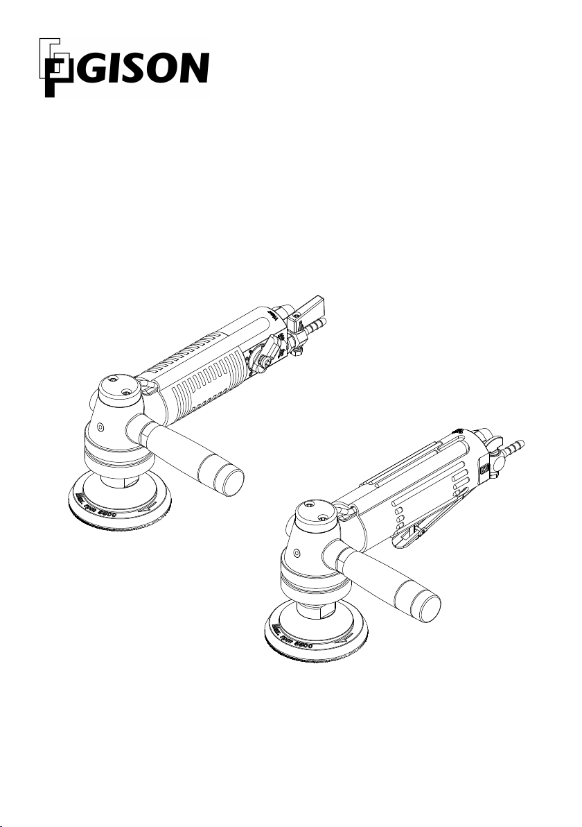
Air Wet Sander,Polisher
Operation Instruction
GPW-7
GPW-7
GPW-7L
GPW-7L
h t t p : / / w w w . g i s o n . c o m . t w

1
5
8
1
3
2
4
7
6
1
4
8
2
3
6
5
9
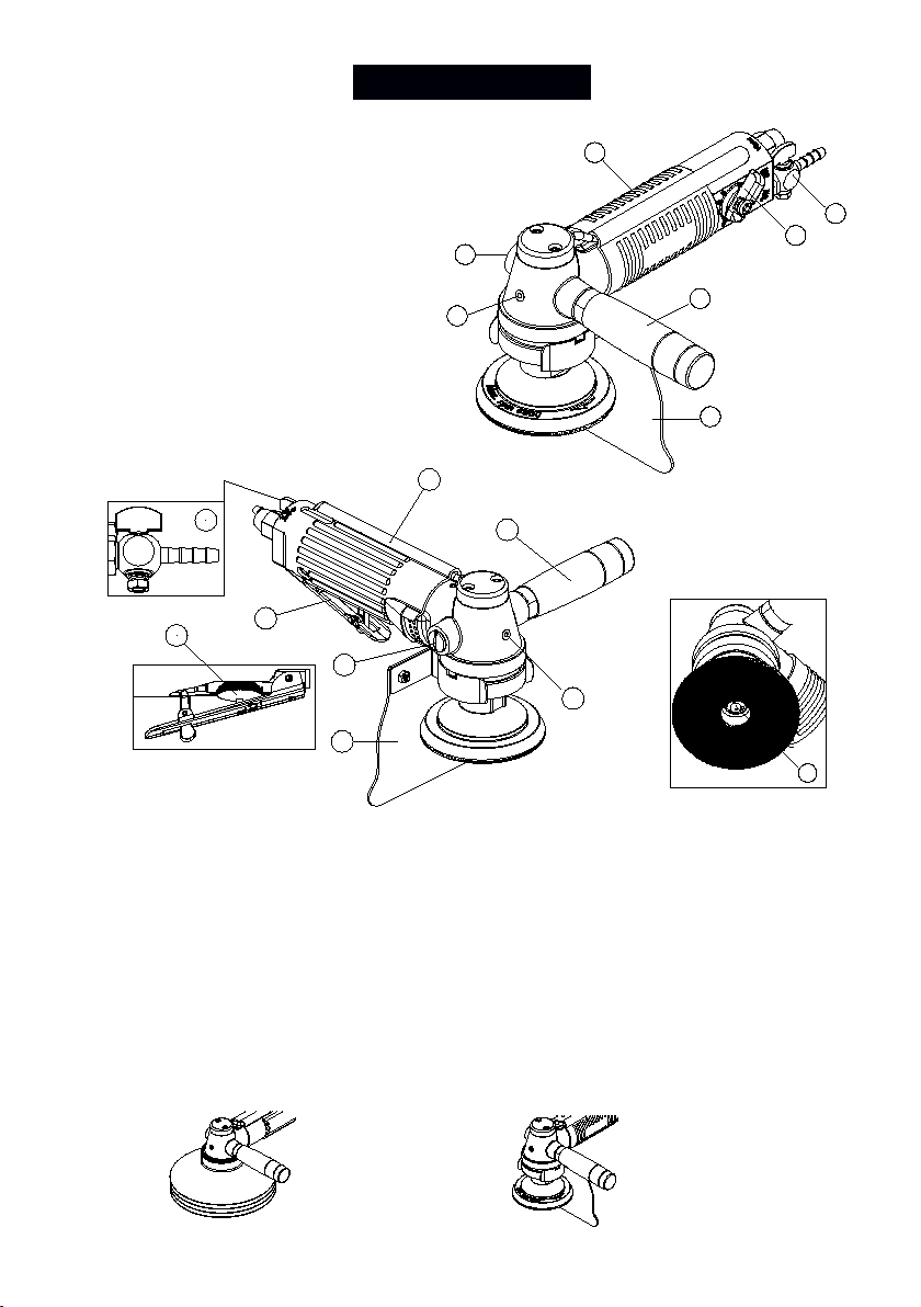
Features
Rubber Sleeve
Excellent material of rubber sleeve prevents slippery when operate the tool.
The rubber sleeve will not oxidize when continuous operation and keep hands
away from getting cold.
Water Shroud
Water guard Water Shroud
GPW-7
GPW-7
GPW-7L
GPW-7L
2
Water Shroud or Water guard for keeping off water prevent users wet their
hands and effect occupational hazards. Fabricators can use water shroud or
water guard depend on their needs. (Additional accessory)
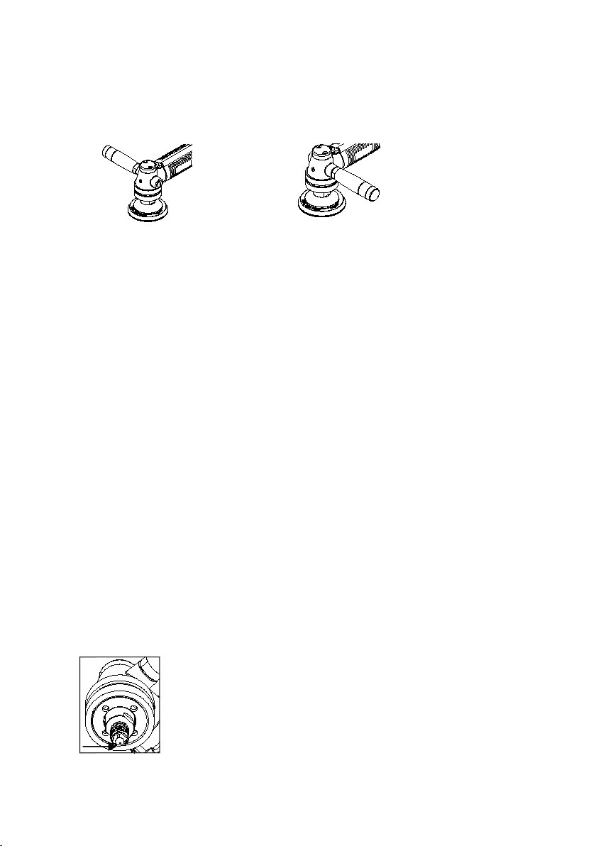
Handles
R-handle L-Handle
Assemble it in right or left side of tool.
Filling Oil from side handle
Take off sice handle and grease gear lubricating oil directly from the hole.
Fabricators can maintain the machine themselves, save maintenance cost
and extend duration of gear.
Water Regulator
Water regulator enables users to adjust frequency of water to proper speed
according to various needs of profiling.
Grip Throttle/Air Regulator
Grip throttle suits continuous operation, speed can be adjusted during
operating.
Air regulator enables users to adjust frequency of air to proper speed
according to various needs of profiling.
Safety Lever Throttle
Avoid users to press the trigger and start the tool carelessly. Just release the
safety lever and the tool will stop performing immediately. Lever throttle with
safety trigger ensures safety while stop operating, postitive speed control.
Grease Hole
Central Waterfeeding
There is a water exit with 3 holes on the spindle. A large
amount of water will spurt from the holes when profiling slab.
It creates high performance and reduce dust.Operators can
disassemble the water exit and clean it if it is choked up.

3
Water Inlet
Water Regulator
Air Regulator
Quick Joint
Air Inlet
Safety Lever
Air Inlet
Water Inlet
Water Regulator
Air Regulator
Quick Joint
Starting Tool
1. Connect tool to air supply.
2. Connect Water Valve to water hose.
3. GPW-7: Turn on Air Regulator to start tool, adjust frequency
of air to proper speed according to various needs of
profiling.
GPW-7L: Press the Safety Lever and adjust the Air
Regulator to proper free speed.
4. Adjust the Water Regulator to proper water flow.
5. Read “Operating Manual” on next page before performing
the tool.
GPW-7
GPW-7
GPW-7L
GPW-7L

4
Operating Manual
Check the following items prior to operation.
1. Make sure that the work site is in order prior to polishing operations.
2. Select and install a compressor with sufficient capacity for the
recommended air consumption. Use of compressed air with water and
oil may cause rusting and other problems. Before operating the
compressor, drain out the water and oil completely through the drain
port provided at the bottom of the compressor tank.
3. Check the operating air pressure. This polisher is designed for
operation in the optimum air pressure at 90 PSI/6 BARS (Max. air
pressure at 8.0 kgf/cm²). Excessive air pressure levels can cause the
polisher to run at excessively high r.p.m. which may cause damage to
the polisher. Only operate this polisher within the specified air
pressure ranges.
Preparation Before Operation :
WARNING
Make the following preparations prior to commencement of
operation. Complete items 1-5 before connecting the air
hose to the compressor.
1. Attach the grip handle to the body.
2. The polisher body, air hose, water hose and exhaust hose are shipped
disconnected. Connect them according to the instructions below.
(1) Connect the water hose first. Warm up the joints first by running
hot water through the hose to facilitate the connetcion.(Take care
to prevent accidental burns when using hot water.)
(2) Guide the air hose through the air hose nut and advance the end
of the air hose onto the air hose joint. Tighten the nut onto the air
hose joint securely. After the nut is tightened, make sure that the
air hose can not be disconnected.
(3) Attach the exhaust hose onto the end case and clamp it with the
high grip provided.
3. Consider Environment, Health and Safety codes before use. Take
necessary measures to comply with local ordinances when operating

5
this polisher.
(1) The normal operating noise level of this polisher is below 84db.
(2) The normal vibration level of this polisher is <2.5 m/s2.
4. Disc Set-Up
WARNING
Prior to setting up the disc, turn off the air valve to prevent
accidental start up.
Disconnect the air hose from the compressor as a safety
precaution.
Disc setting sequence :
(1) Attach the backer pad or adapter to the spindle. Hand tighten
using the spanner wrench provided.
(2) Attch the disc or polishing accessory.
(3) To remove, follow the reverse sequence.
5. Check the switch function.
Grip the body while holding the switch lock forward. Then push the
switch lever down to turn the tool "on". The switch will shut off
automatically when the lever is released. Turn the air regulator valve
for air flow control from zero to max.
6. Check the switch "off".
Make sure that the switch is off prior to connecting the air hose. If the
switch is on, this may cause accidental start up. Make sure that the
switch is off whenever this tool is on a work bench or resting on other
surfaces.
7. Connection of the air hose from the compressor to the tool.
(1) Check the air hose connection plug for small stone particles and
dust. Foreign Object Damage (FOD) can be caused by these small
stone particles if they get into the tool.
(2) Prior to connecting the air hose, make sure that it is not damaged
and the connecting joint is tightly clamped. Connect the air hose to
the compressor and the tool and make sure they air secure.
8. Test Run

6
CAUTION
˙ Prior to switching on, make sure that the tool is not in
contact with the work piece.
This may damage the work piece or cause personal
injury.
˙ When switching on, the operator should be positioned
away from the exposed portion of the disc.
Before polishing, perform a test run with the polisher. Take care to
ensure that no one is in the immediate area during the test run. During
the test run, make sure that the polisher is running normally and that
the disc is properly set.
Test Run Times
Disc Changes………………………………...More than 3 Minutes
Start of Operations……………...……………………...1-2 minutes
WARNING
˙ Turn the switch off whenever polishing operations are
interrupted, discs are changed, after completion of
polishing, and when the air hose is to be disconnected.
˙ Use protective glasses while polishing.
˙ Handle your polisher with care. Improper contact with
other materials may cause damage to the disc or to the
polisher. Continuing polishing operations with cracked or
damaged discs is hazardous and could result in physical
injury. If the polisher is dropped, perform a test run before
resuming operation. Make sure that the tool is working
properly before continuing.

7
Grease Hole
Safety Rules
Read all instructions before using this machine. All operated must
be fully trained in its use and aware of these safety rules.
Also lubricate the tool after performance.
Before operating the tool, pour 20cc suitable motor lubricating oil
into Air Inlet. Run the tool for few seconds to allow air to circulate
the oil and well lubricate the cylinder. This will ensure top
performance and maximum durability of tool.
When starting the sander without pad, it exhausts air too soon to
cool the internal parts and generates hear. Always install pad
when performing the sander. The sander can be performed
without pad when lubricating the cylinder.
Supply tool with 90psi (6.3kg/cm²) of clean and dry air. Higher
pressure raises performance beyond the rated capacity of the
tool will shorten the tool’s life because of faster wear and could
cause injury.
Unscrew L-handle Screw and grease every
week for extending durability of gear.
If the machine appears to malfunction
remove from use immediately and arrange
for service and repair.
8
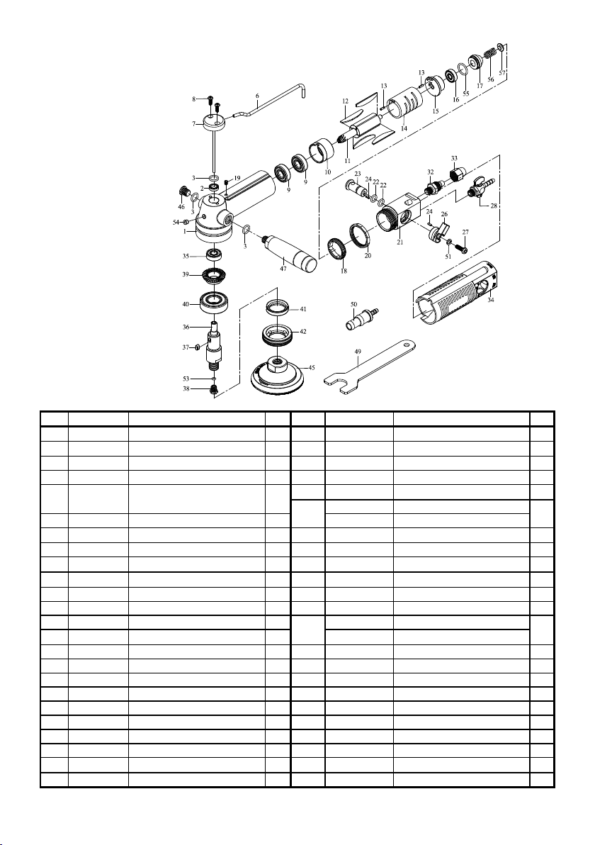
GPW-7 Wet Air Sander/Polisher
PARTS LIST
:Consuming Parts
No.
Part No.
Description
Qty.
No.
Part No.
Description
Qty.
1
7W001
Main Body
1
28
7W019S
Water Cock
1
2
SG009
Oil Seal
1
32
7W042
Air Inlet Nozzle
1
3
OR006
O-Ring
3
33
7W043
Hose Adaptor
1
6
7W020
Water Inlet Tube
1
34
7W021
Rubber Glue
1
7
7W023A
Water Inlet Transfer Post
1
35
B608LLU
Bearing
1
w/brass tube
36
7W027D
Main Shaft (5/8”)
1
8
MC007
Screw
2
7W027E
Main Shaft (M14)
9
B6000LLU
Bearing
2
37
KC003
Locking Key
1
10
7W004
Cylinder Cap
1
38
829055W
Water Exit
1
11
7W006
Rotor
1
39
7W029
Spiral Gear
1
12
7W007
Blade
4
40
B6203LLU
Bearing
1
13
SP014
Spring Pin
2
41
SG011-1
Oil Sealer
1
14
7W005
Cylinder
1
42
7W033
Locking Screw Cap
1
15
7W008
Rear Cylinder Cap
1
45
7W037
3” Sanding Pad
1
16
B626LLU
Bearing
1
7W037-1
4” Sanding Pad
17
7W003
Dust-Proof Plug
1
46
7W040
Cap Screw
1
18
7W011
Locking Cap
1
47
7W038
Handle
1
19
MS010
Screw
1
49
829048
Stop Spanner
1
20
7W012
Locking Ring
1
50
7W019-1
Water Valve
1
21
7W013
Shifting Post
1
51
SPW5
Spring Washer
1
22
OR030
O-Ring
2
53
OR052
O-Ring
1
23
7W014
Air Plunger
1
54
221A10800
Grease Hole
1
24
SP033
Spring Pin
2
55
OR042
O-Ring
1
26
7W016
Shifting Knob
1
56
S079
Spring
1
27
MC008
Locking Screw
1
57
7W002
Spring Cushion
1
※
If you need to order parts, please mark both Parts No. and Description. 2011/1/13

9
GPW-7L Wet Air Sander/Polisher
(Safety Lever)
PARTS LIST
: Consuming Parts
No.
Part No.
Description
Qty.
No.
Part No.
Description
Qty.
1
7W001
Main Body
127
7W029
Spiral Gear
1
2
SG009
Oil Sealer
128
B6203LLU
Bearing
1
3
OR006
O-Ring
329
SG011-1
Oil Sealer
1
4
OR044
O-Ring130
7W033
Locking Screw Cap
1
6
7W020
Water Inlet Tube
1337W037
3” Sanding Pad
1
7
7W023A
Water Inlet Transfer Post
1
7W037-1
4” Sanding Pad
w/brass tube
34
7W040
Cap Screw
1
8
MC007
Screw235
7W038
Side Handle
1
9
B6000LLU
Bearing
236S046
Spring
1
10
7W004
Cylinder Cap
137218L027
Valve Pin
1
11
7W006
Rotor138
OR030
O-Ring
2
12
7W007
Blade439
7WL046
Air Plunger
1
13
SP014
Spring Pin
240DR001
Riveter
1
14
7W005
Cylinder
141P011
Pin
1
15
7W008
Rear Cylinder Cap
142829005A
Throttle Lever
1
16
B626LLU
Bearing
143SP026
Spring Pin
1
17
7W003
Dust-Proof Plug
1447W019S
Water Cock
1
18
7W011
Locking Cap
1487W042
Air Inlet Nozzle
1
19
MS010
Screw149
7W043
Hose Adaptor
1
20
7W012
Locking Ring
150829048
Stop Spanner
1
21
7WL045
Shifting Post
1517W019-1
Water Valve
1
22
7WL044
Rubber Sleeve
153OR052
O-Ring
1
23
B608LLU
Ball Bearing
1
54
221A1080
0
Grease Hole
1
24
7W027D
Main Shaft (5/8”)
1
55
OR042
O-Ring
1
7W027E
Main Shaft (M14)
56
S079
Spring
1
25
KC003
Locking Key
1577W002
Spring Cushion
1
26
829055W
Water Exit
1
※
If you need to order parts, please mark both Parts No. and Description. 2011/1/14

GISON Machinery Co., Ltd.
No.6, Alley 105, Lane 68, Sec. 2, Sinan Road, Wurih,
Taichung 41466, Taiwan
Tel : +886-4-23353202 Fax : +886-4-23352252 / 23357742
E-Mail : gison@seed.net.tw / sales@gison.com
Web-Site: http://www.gison.com.tw
Printed in Oct. 2017
 Loading...