

Giropes GI 430 User Manual
USER MANUAL | EN | GI430
GI 430
USER MANUAL
SOFTWARE FOR WEIGHING LORRIES
V.3.3 22/10/2018
EN
1
Pol. Empordà Internacional Calle F. Parcela 15-16
17469 VILAMALLA - (Girona) SPAIN T. (+34) 972 527 212 - F. (+34) 972 527
El fabricante se reserva el derecho de modificar sin previo aviso las características de sus productos para introducir mejoras técnicas o cumplir con nuevas
regulaciones oficiales./Le constructeur se réserve le droit de modifier les caractéristiques de ses produits en vue d’y apporter des améliorations techniques
ou de respecter de nouvelles réglamentations./The manufacturer reserves the right to modify the specifications of its products in order to make technical
improvements or comply with new regulations.
211
2
GI430 | EN | USER MANUAL
1. INTRODUCTION 05
1.1 Indicator features 05
1.1.1 Analogue load cell connection 05
1.1.2 User interface 06
1.1.3 Serial communications 06
1.1.4 Supply 06
1.1.5 Operating conditions and mechanical data 06
1.2 General Features 06
1.3 Keyboard and functions 08
1.4 Display 10
1.5 Operational 11
1.5.1 Indicator activation 11
1.5.2 Weight display 11
1.5.3 Zero 11
1.5.4 Tare 12
1.5.4.1 Standard tare 12
1.5.4.2 Manual tare 12
1.5.4.3 Deactivate Tare 12
2. WEIGHING INTRODUCTION 13
2.1 Description of function keys 13
2.2 Obtaining the net weight using two weights 13
2.2.1 First weight 13
2.2.2 Second weight 15
2.3 Obtaining the net weight using a single weight 16
2.3.1 Weighing a vehicle with memorised tare 16
2.3.2 Weighing a vehicle with manual tare 18
2.3.3 Weighing a vehicle using indicator tare 20
2.4 Printing a ticket for the last recorded weight 22
3. DATABASE (TABLES) 22
3.1 Free code tables 23
3.1.1 ADD Function 23
3.1.2 EDIT Function 23
3.1.3 DELETE Function 24
3.1.4 PRINT TABLE Function 24
3.2 Number table 24
3.2.1 DO SINGLE WEIGHT Function 24
3.2.2 ADD Function 25
3.2.3 EDIT Function 25
3.2.4 DELETE Function 25
3.2.5 PRINT TABLE Function 25
3.3 Table of numbers in transit 26
3.3.1 DO SINGLE WEIGHT Function 26
3.3.2 DELETE Function 26
3.3.3 DELETE ALL Function 26
USER MANUAL | EN | GI430
3.3.4 PRINT TABLE Function 26
3.4 WEIGHTS table 27
3.4.1 EDIT Function 27
3.4.2 DELETE Function 28
3.4.3 DELETE ALL Function 28
3.4.4 PRINT TABLE Function 28
3.4.5 FILTER Function 28
4. SETUP DESCRIPTION (NON METROLOGICAL) 29
4.1 COMMUNICATIONS 29
4.1.1 COM1(RS232) AND COM2(RS232) 30
4.1.2 ETHERNET 31
4.1.3 COM 3 (RS485) 32
4.2 REGIONAL CONFIGURTION 33
4.2.1 PASSWORD 33
4.2.2 DATE / TIME AND LANGUAGE 33
4.3 PRINTER 34
3
4.3.1 HEADER AND FOOTER 34
4.3.2 TICKET CONFIGURATION 34
4.3.2.1 TICKET_ID 34
4.3.2.2 INCREASE TICKET ID 34
4.3.2.3 FIRST WEIGHT TICKET 34
4.3.2.4 SECOND WEIGHT TICKET 34
4.3.2.5 SINGLE WEIGHT TICKET 34
4.3.2.6 PRINT COPIES (FIRST, SECOND OR SIGLE WEIGHING) 35
st
4.3.3 CONFIGURATION 1
4.3.4 CONFIGURATION 2
WEIGHT TICKET 35
nd
WEIGHT TICKET AND SINGLE 35
4.3.5 PRINTER CONFIGURATION 35
4.4 DIAGNÓSTICO 36
4.4.1 mV CELL 36
4.4.2 I. COUNTS 36
4.5 ADDITIONAL 36
4.5.1 TRAFFIC LIGHTS AND BARRIERS 37
4.5.2 DATA STORAGE DEVICE (FISCAL MEMORY) 37
4.6 DATABASE CONFIGURATION 38
4.6.1 DATA BASE START-UP 38
4.6.2 DATABASE CONFIGURATION 38
4.7 EQUIPMENT INFORMATION 39
5. DISPOSAL OF ELECTRONIC EQUIPMENT (WEEE) 39

4
GI430 | EN | USER MANUAL
USER MANUAL | EN | GI430
0. SET-UP
SET-UP
1- CONNECT THE DEVICE TO A SUITABLE WALL SOCKET (SEE POINT 1)
2- CONNECT THE CELL CONNECTOR TO THE DISPLAY
*IF YOU HAVE A USB KEYBOARD OR OTHER PERIPHERALS CONNECT THEM TO THE DEVICE AS WELL (SEE POINT 1)
3- WITH THE DEVICE CALIBRATED, YOU CAN FORMAT THE DATABASE (SEE POINT 4.6.1)
4- FILL IN THE FIELDS REQUIRED BY THE DATABASE (SEE POINT 3)
5- OPERATE ACCORDING TO (POINT 2)
1. INTRODUCTION
1.1 SETUP DESCRIPTION
5
1.1.1 ANALOGUE LOAD CELL CONNECTION
Maximum input signal ±3 mV/V
Input impedance From 25
Internal resolution 24-bit AD converter, 16,700,000 calculations
Measurement frequency 50 measurements per second
Linearity error
Zero-point stability 150 nV/ºC max.
Gain stability 3.5 ppm / ºC max.
Excitation voltage 6 ± 0.3 VDC
Minimum transducer resistance 43
Maximum transducer resistance 1000 k
Maximum input current ± 6.8 V
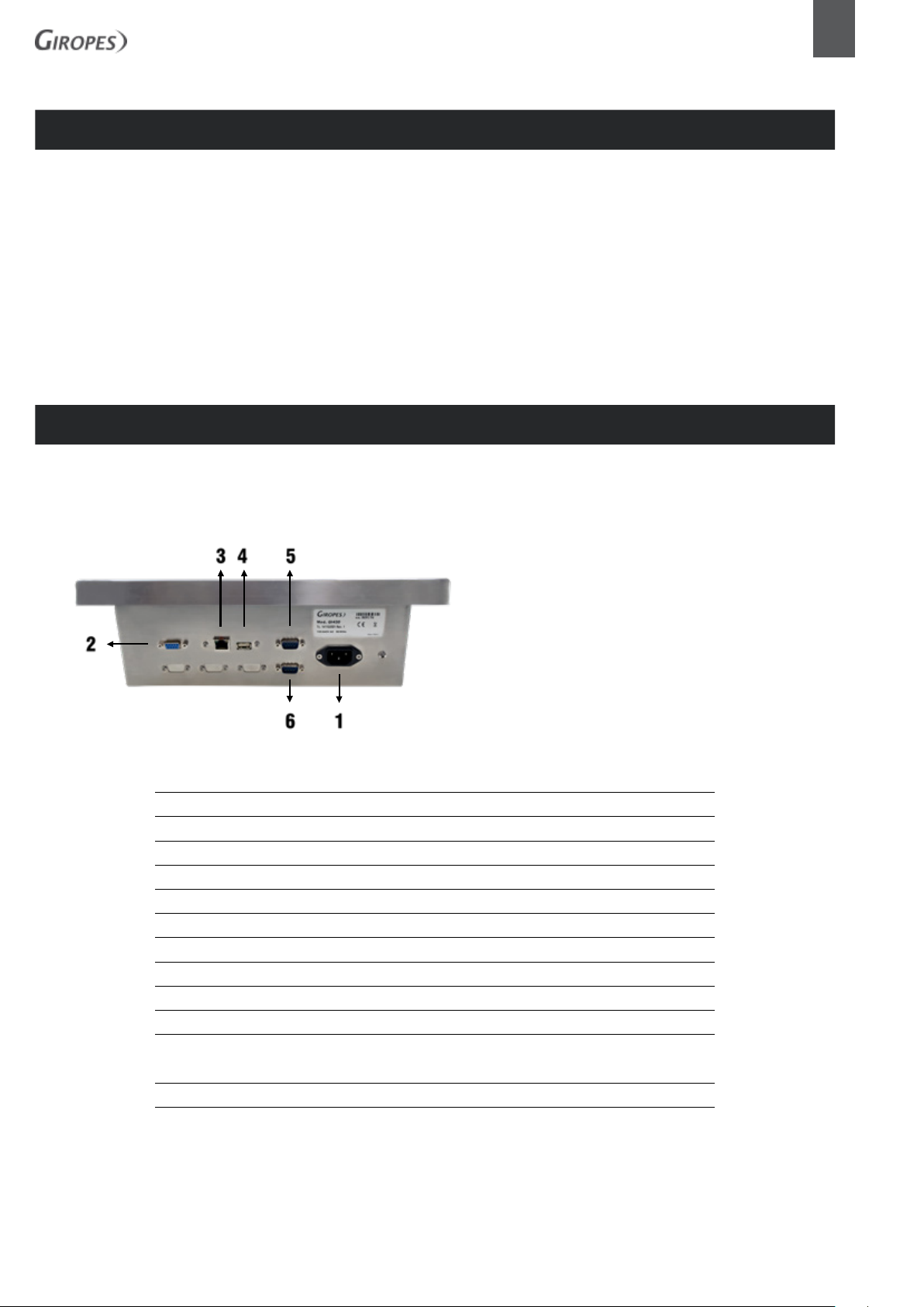
Légende:
1. Power connector
2. Charging cell connector
3. ETHERNET connector (RJ-45)
4. USB connector
5. COM 1 connector (RS-232)
6. COM 2 connector (RS-232)
Ω to 1100Ω
Ω 0.01 % of the measurement range
Ω (8 cellsx350Ω, 16 cellsx700Ω)
Ω
Cable length 400 m/mm2 max. (6 threads)
30 m/mm2 max. (4 threads)
6
GI430 | EN | USER MANUAL
1.1.2 USER INTERFACE
1.1.3 SERIAL COMMUNICATIONS
1.1.4 SUPPLY
Display 240x128 backlit LCD graphic
Keyboard 24-key membrane keyboard
External keyboard (optional) Standard PC, USB connector
Port Tx/Rx: (Channel 1) RS-232C bi-directional
Port Tx/Rx: (Channel 2) RS-232C bi-directional
Port Tx/Rx: (Channel 3) RS-485 half-duplex
Transmission speed 115200, 57600, 38400, 19200, 9600 and 4800 bauds
Number of bits and parity 7 and 8 bits, both without parity, with even parity or
with odd parity
Network connection 110-230 VAC, 50-60 Hz,
DC supply 15 VDC
1.1.5 OPERATING CONDITIONS AND MECHANICAL DATA
Operating temperature range -10°C to 40°C
Temperature limit -25°C to 70°C
Assembly Desktop or wall-mounted, according to model
1.2 GENERAL SPECIFICATIONS
GRAPHIC DISPLAY
The GI430 terminal has a graphic display.
PASSWORD
All programming functions protected via password.
CODE ARCHIVE MANAGEMENT
You may manage an archive of up to 2000 entries.
These archives are used to manage 4 types of code (500 configurable records per code)
For example, Company, Material, Transport, Destination. In addition, it is possible to program a specific name for each code, configurable
within the database menu.
REGISTRY MANAGEMENT
The equipment also has a archive of 500 configurable records for registrations, with editable names.
Size
Weight
WEIGHT MANAGEMENT
You may store up to 4500 weights; the number of records is calculated as this quantity, minus the registry numbers used in the codes of
the separate files.
When the maximum number of registry numbers are assigned to each code, the available storage is 2000 weights.
MANAGEMENT OF STORED TARES
You may manage up to 500 tares. (This is configurable)
MANAGEMENT OF LORRIES IN TRANSIT
You may manage up to 200 lorries in transit.
TYPES OF WEIGHTS
It is possible to execute one of the following types of weights:
▪ input weight
▪ output weight
▪ weight with stored tare (single weighing)
PRINTERS
The peripherals supported for printing are the following:
▪ thermal printer, 24 type columns plus2B (COM1 o COM2)
▪ (Internal printers should always be connected to COM1)
▪ continuous tape printer, 80 type columns LX350 (COM1 o COM2)
▪ 40-column type ticket printer ESC/POS/TM295 (COM1 o COM2)
▪ Thermal printer BTPR990 (COM 1 O COM 2)
USER MANUAL | EN | GI430
7
All peripherals can be enabled or disabled for the various prints via the settings menu. The prints available are as follows:
▪ Input printing
▪ Output printing
▪ Printing with manual tare
▪ Print CODES file
▪ Print REGISTRATIONS file
▪ Print file of all weights taken
▪ General printing
▪ Print lorries in transit
STANDARD PERSONAL COMPUTER KEYBOARD
To configure the terminal, you can connect a standard USB computer keyboard.
This is very useful when it is necessary to enter alphanumeric characters into the configuration (ticket headers, clients names...)
MAXIDISPLAY RP100 MANAGEMENT
▪ Connection via RS-232, RS-485 or Ethernet
▪ Transmission of net weight
TICKET FORMAT
You may select the printing fields associated with first-weight, second-weight and single-weight tickets.
I/O ADDRESS
Allows you to manage an indicator light placed at the scale opening (OUT1) to indicate that the scale is occupied and therefore not
available for weighing operations.
It also allows you to manage an indicator light at the scale exit (OUT2) to indicate the end of the weighing / scale output process.
If the i-button is being used, the indicator will show the correct reading (OUT3), and in the event of any error (data not present, or a
weight error) the emergency indicator (OUT4) will activate.
8
GI430 | EN | USER MANUAL
DSD MEMORY
It is possible to implement the lorry-weighing operation with the additional panel that performs the FISCAL MEMORY function. This
involves archiving all the weight values transmitted to a computer via the COM serial channel or ETHERNET, for further processing or
integration via PC. (As a control with regard to the data printed by the PC).
Each archived weight is associated with a two-digit ID code. The stored value can be viewed on the screen of the indicator by entering the
ID, or by entering a command on the PC.
The ID has the following format: <Unique code number>-<Weight number>
Unique code number: a 5-digit number ranging from 0 to 99999, which increases for each 400,000 weights memorised.
Weight number: a 6-digit number ranging from 0 to 399999, which increases for each weight memorised.
Entering the command “PID” on a PC will cause the weight ID, gross weight and tare weight to be recorded and accurately identified
during weighing, as long as the platform is stable and the gross weight is non-negative and greater than the minimum weight.
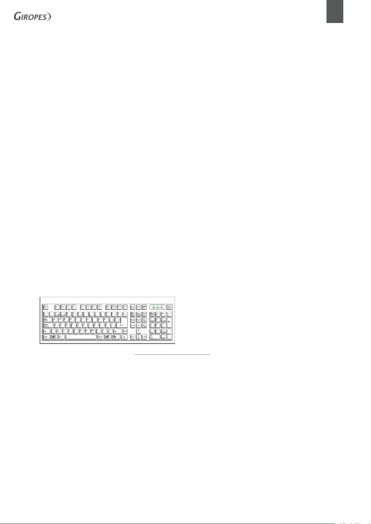
1.3 KEYBOARD AND FUNCTIONS
The keyboard, located on the front of the device, is of the membrane type and has 24 keys.
Its arrangement can be seen in figure
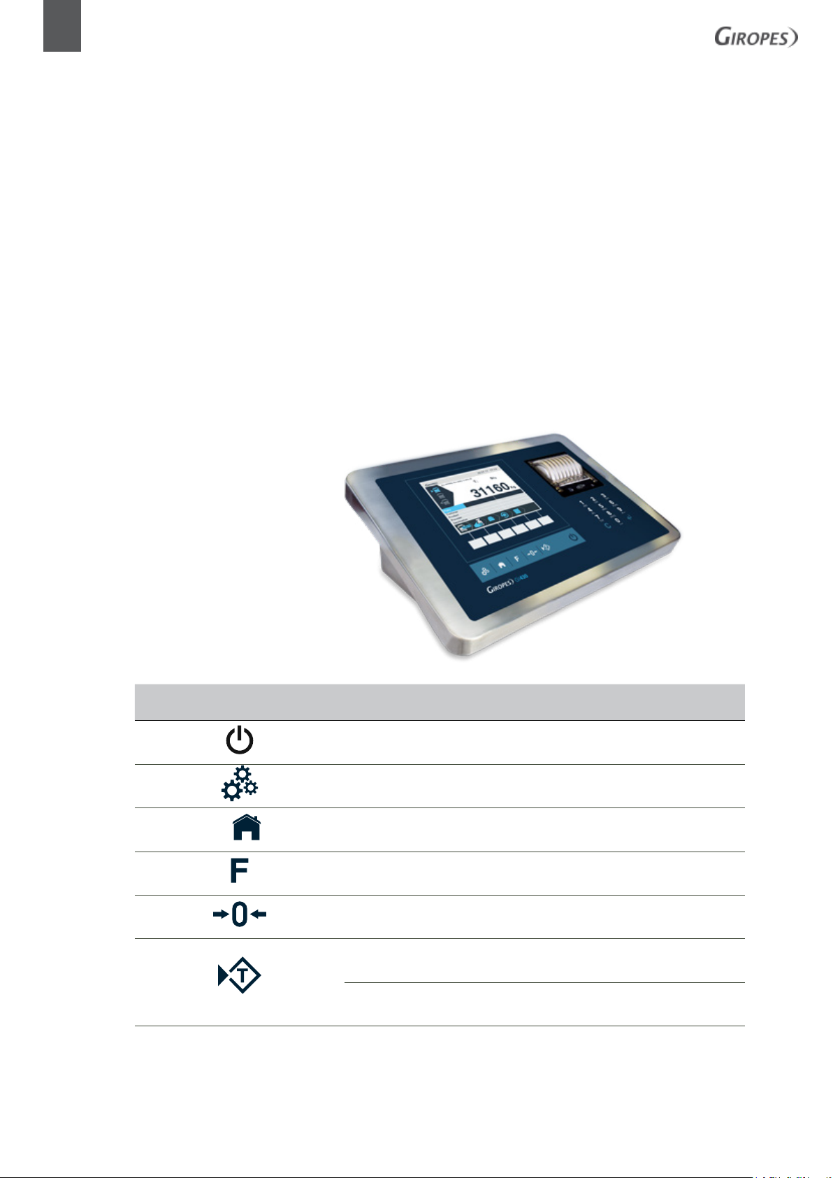
TECLAS DE O
OPERATING KEYS DEFINITION KEY KEYBOARD
Activated-Deactivated
Adjustments F9
Return to the main weighing screen Inicio
Does not function in lorry-weighing models F8
Set to zero F10
Short press = TARE
(Only available outside of legal metrology)
Long press= DE-TARE F12
F11
ALPHA-NUMERIC KEYS
GI430
KEYBOARDKEYS
B1234JKL
USER MANUAL | EN | GI430
9
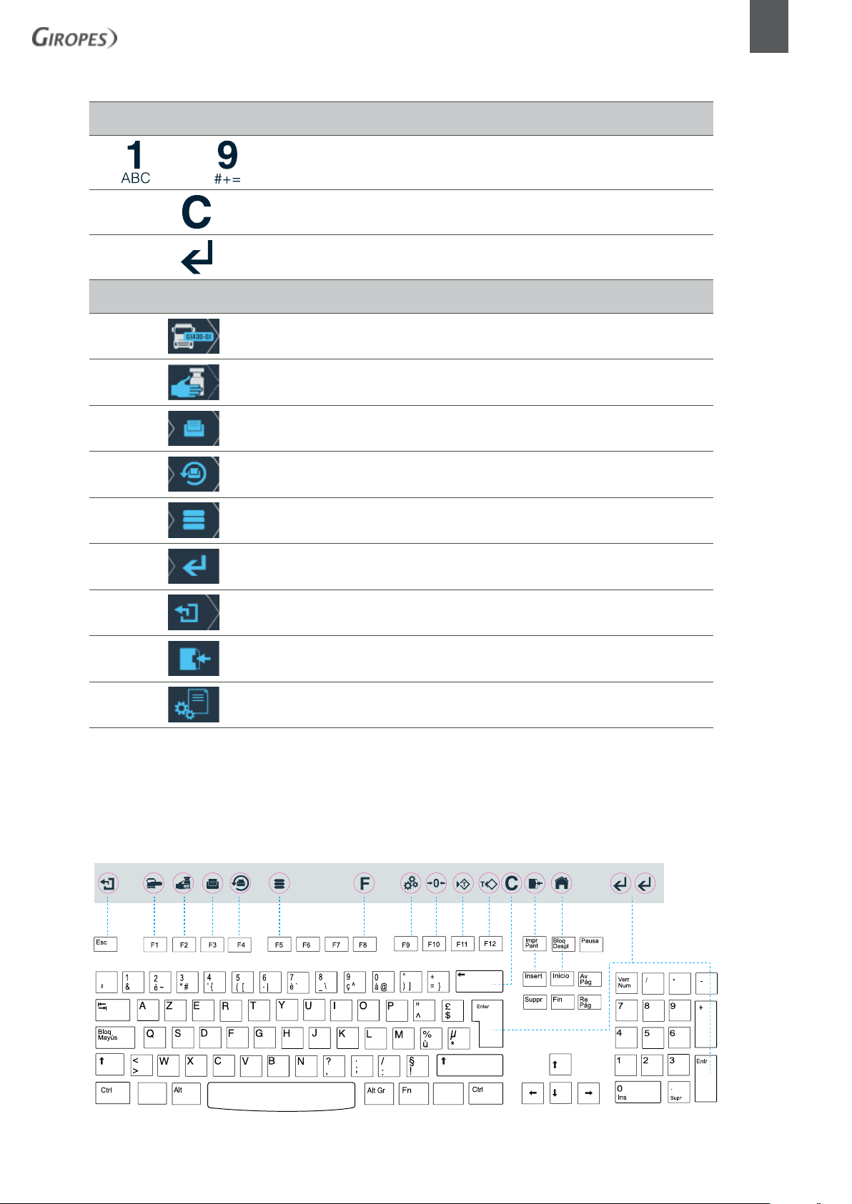
DISPLAY KEYS
alpha-numeric keys
KEYS
ALPHA-NUMERIC
Delete key
Enter key INTRO/ENTER
Data entry for new weight F1
Manual tare F2
Direct access to registered entities in transit F3
Re-printing F4
Access to the database F5
Confirm key INTRO/ ENTER
Back ESC
Save data (add data to memory ) INSERT
Access the registry settings INTRO/ ENTER
Inside the GI430 packaging, you will find a sheet of sticky labels, along with a sheet describing the corresponding positions of the icons on the
USB keyboard.
10
GI430 | EN | USER MANUAL
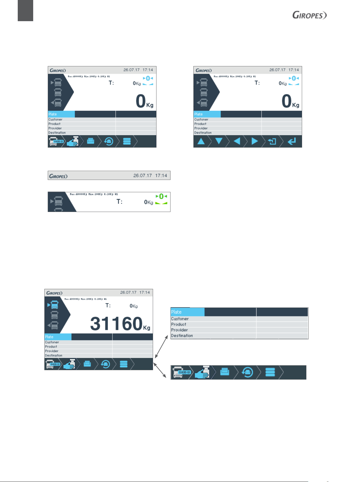
1.4 DISPLAY
The indicator consists of a graphic display which you can see in figure
Figure.1 Display status
Figure 2 the top right shows the date and time
Figura 3
The upper section states the maximum capacity value of the scale, the minimum capacity value of the scale, the number corresponding to E, and the weighing range (w).
The same area will also display and indicate instances of MANUAL TARE o MEMORIZED TARE: MAN
The stability and zero icons will then be activated once the weight of the scale is stable, and will indicate the weight at the same
time when the scale returns to the value 0, without any weight.
Just below and occupying the full width is the main weighing indicator, which shows the weight of the scale.
The following shows the area of the records on the database. During
weighing, this section is used for entering data (registration, company,
product, etc ...)
Lastly, the icons that assign functionality to the context keys will
appear.
FUNCTIONALITY
STABLE INDICATION
USER MANUAL | EN | GI430
11
NET
o
W1/W2
T: 0.000 kg
INDICATION WITH TARE
INDICATING SYSTEM ZERO
RANGE SITUATION
INDICATION OF THE TARE VALUE
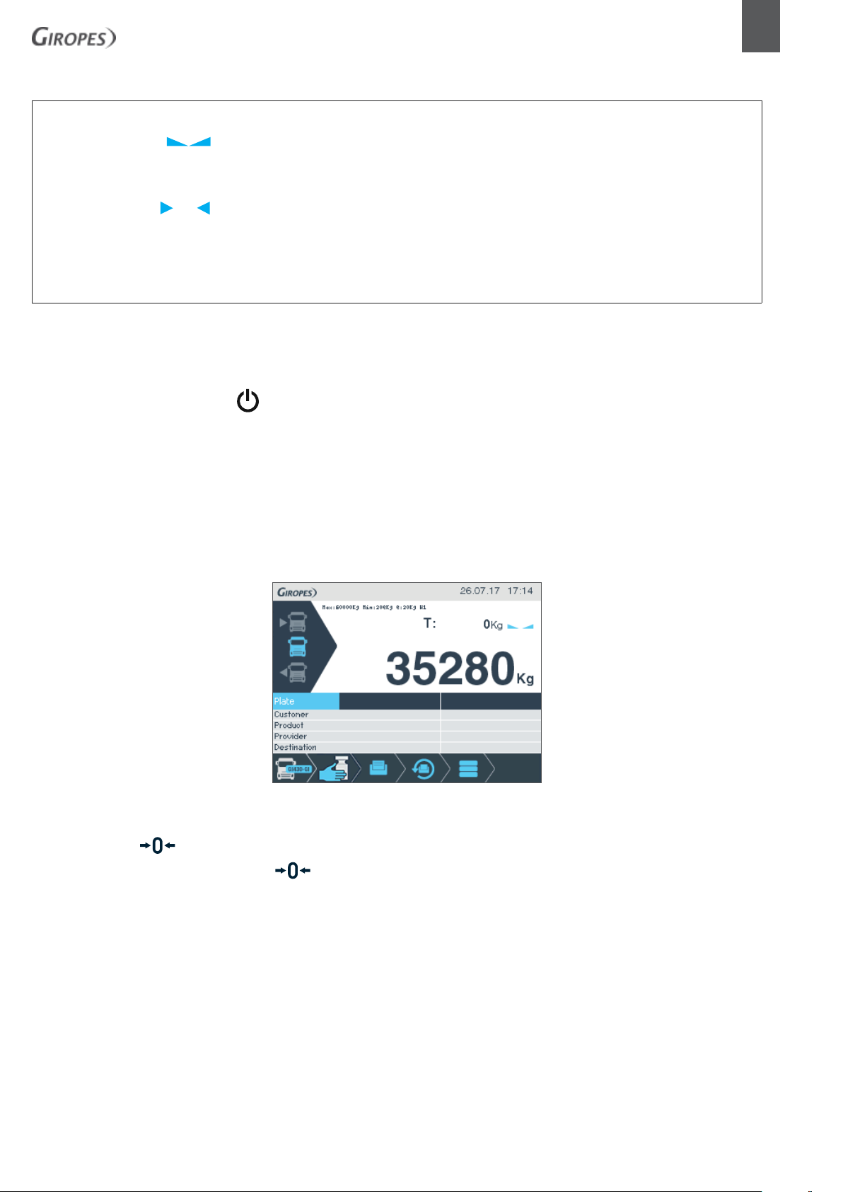
1.5 OPERATIONAL
1.5.1 INDICATOR ACTIVATION
The indicator lights up using the button on the front panel of the computer keyboard once you are connected to the electricity
network. Before using the equipment, it is best to let it stabilise for a while. This is especially important when performing a
calibration. In this case it is advisable to wait for about 30 minutes. In order to avoid warm-up times and possible condensation in
the event of significant external temperature changes, the equipment can be left permanently connected.
1.5.2 WEIGHT DISPLAY
Upon loading the platform, the weight of the scales will be indicated on the graphic display
1.5.3 ZERO ( , F10)
The indicator has a manual reset. If the key is pressed, the indicator will capture the current weight value as system zero, as long
as the current value displayed is within the supported range.
12
GI430 | EN | USER MANUAL
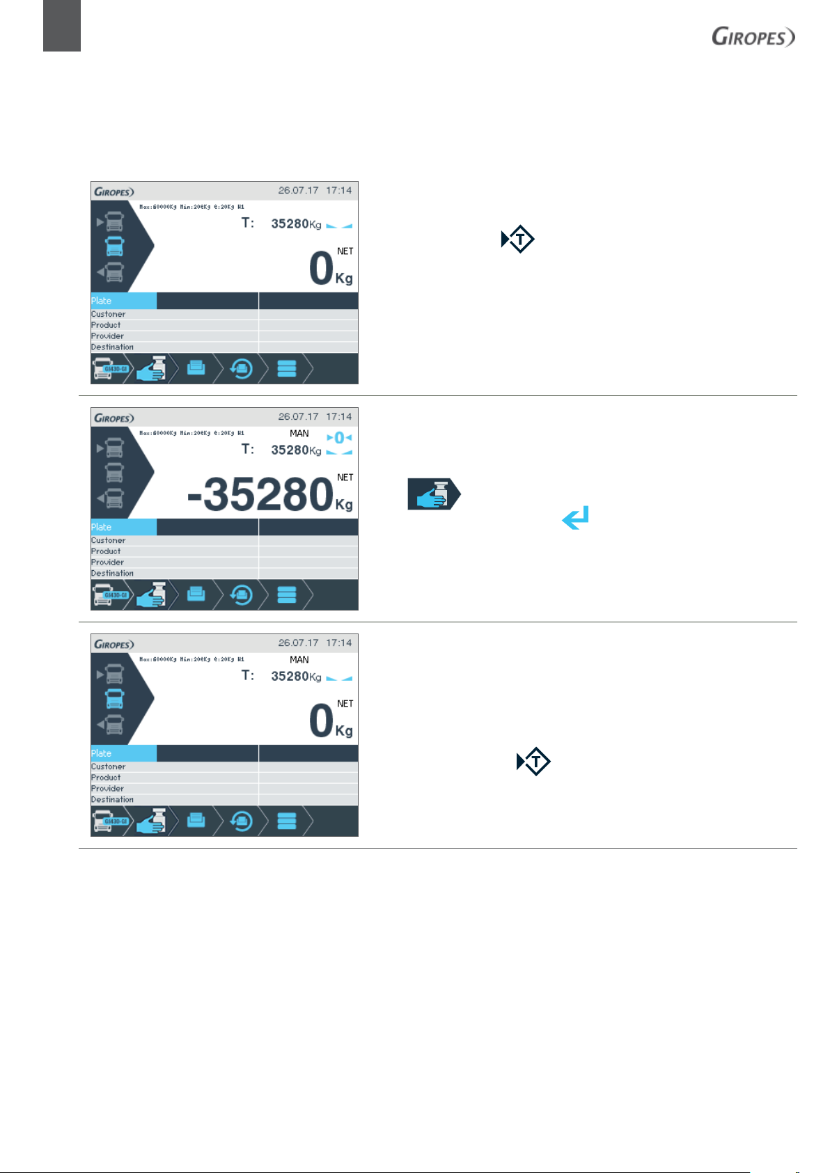
1.5.4 TARE
There are different types of tare that are described in the following sections.
1.5.4.1 NORMAL TARE , F11 on the USB keyboard
When the tare key is pressed, the current value of the indicator is taken as the tare
and the weight display changes to zero. To the right of the weight the word NET will
be displayed, indicating that the weight shown is now net weight.
1.5.4.2 MANUAL TARE
Press orF2 on the USB keyboard and indicate the value of the tare
using the numeric keys. Confirm with .
You will see the message
been entered manually. You will also see the alert NET next to the weight, indicat-
ing that the weight shown is now the net weight.
1.5.4.3 DISABLE TARE
To disable the active tare.
Hold down or press once on F12.
MAN above the tare value, indicating that the value has
 Loading...