

Page 1
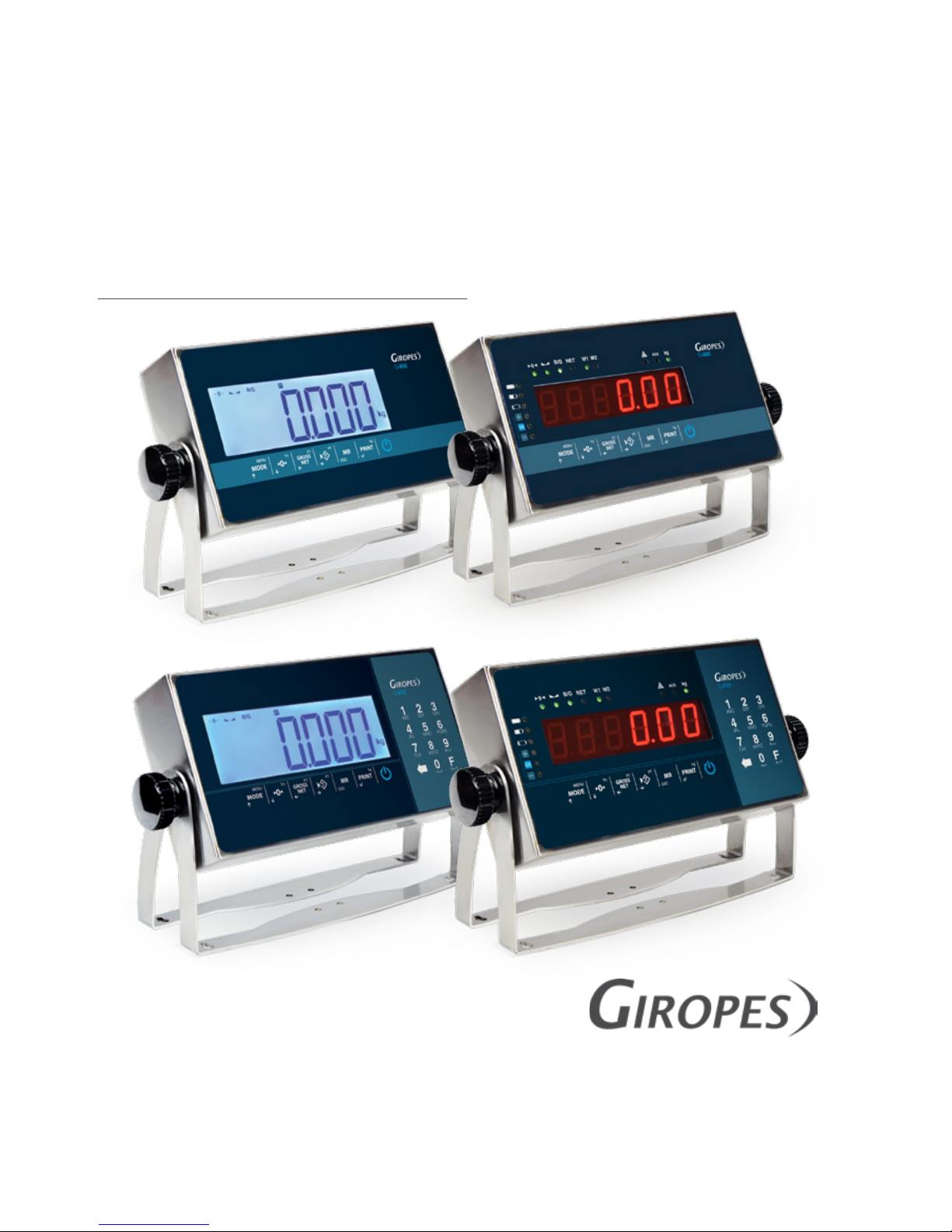
GI410 LED
GI410 LCD
V.4.5_29/11/2018
EN
INDUSTRIAL WEIGHING INDICATOR
GI 400 - GI 410
USER MANUAL
El fabricante se reserva el derecho de modificar sin previo aviso las características de sus productos para introducir mejoras técnicas o cumplir con nuevas
regulaciones oficiales./Le constructeur se réserve le droit de modifier les caractéristiques de ses produits en vue d’y apporter des améliorations techniques
ou de respecter de nouvelles réglamentations./The manufacturer reserves the right to modify the specifications of its products in order to make technical
improvements or comply with new regulations.
GI410 LED
GI400 LED
GI400 LCD
GI410 LCD
Pol. Empordà Internacional Calle F. Parcela 15-16
17469 VILAMALLA - (Girona) SPAIN
T. (34) 972 527 212 - F. (34) 972 527 211
Page 2

ENUSER MANUAL GI400 / GI410
2
EN
1. MECHANICAL DESCRIPTION 3
1.1 FRONT PANEL 3
1.2 BACK PANEL 5
2. CONNECTION 6
2.1 TEST PHASE 6
2.2 DISPLAY OF THE SERIAL NUMBER 6
2.3 SETTING THE INITIAL ZERO 6
3. EXECUTABLE FUNCTIONS 7
3.1 SETTING THE SCALE TO ZERO 7
3.2 WEIGHT 7
3.3 TARE, CONSECUTIVE TARAS, GROSS-NET 7
3.4 BLOCKING/UNBLOCKING TARE 7
3.5 MANUAL TARE 7
3.6 MEMORIZED TARAS TLU 7
3.7 ACCUMULATION (ONLY WORKS WITH THE PRINT ENABLED PROTOCOL) 7
3.8 WEIGHT TOTALIZATION 8
4. OPERATION MODES (USER MENU) 8
4.1 CALCULATION OF THE AVERAGE UNIT WEIGHT CALAUU 9
4.2 PIECE COUNTING AUU 9
4.3 CHECKWEIGHER CHECKW 9
4.4 CHECKWEIGHER SIMPLE CCt SI 11
4.5 IT SHOWS THE WEIGHT WITH ONE MORE DECIMAL, FOR ACURACY BY 10 11
4.6 ACCUMULATION ACCUMU 12
4.7 SUBTOTAL SUBTOT 12
4.8 TOTALIZATION 12
4.9 CODE TCODE 12
4.10 NUMBER OF TICKET NTIC 13
4.11 WEIGHT MODE WEIGH 13
4.12 DOSAGE DOSIFI 13
4.13 LIMITS LIMIT 14
4.14 ACTIVITY CONTROL 2 REL 15
4.15 DATA DISPLAY MEMORIA DSD 15
4.16 MEMORIZED TARAS TLU 16
4.17 ANALOG OUTPUT (ONLY FOR LED DEVICES) 17
4.18 FUNCTION MENU FUNCIO 17
5. SPECIAL FUNCTIONS OF THE NUMERICAL KEYBOARD 17
6. NO METROLOGICAL TECHNICAL MENU 24
6.1.MENU PARAME : COM1, COM2, RS485 Y COM4 25
6.2 ETHERNET MENU 27
6.3 CONFIGURATION MENU 29
6.4 ABT VM 30
6.5 DEFAUL
30
7. PRINTER 30
7.1 TICKET FORMATS GI400 30
8. ERROR MESSAGES 33
9. CONNECTIONS 34
10. DSD MEMORY 39
11. REMOVAL OF ELECTRONIC EQUIPMENT 40
12. OPTIONAL BATTERY 40
13. WARRANTY
40
Page 3
3
ENUSER MANUAL GI400 / GI410
1. MECHANICAL DESCRIPTION
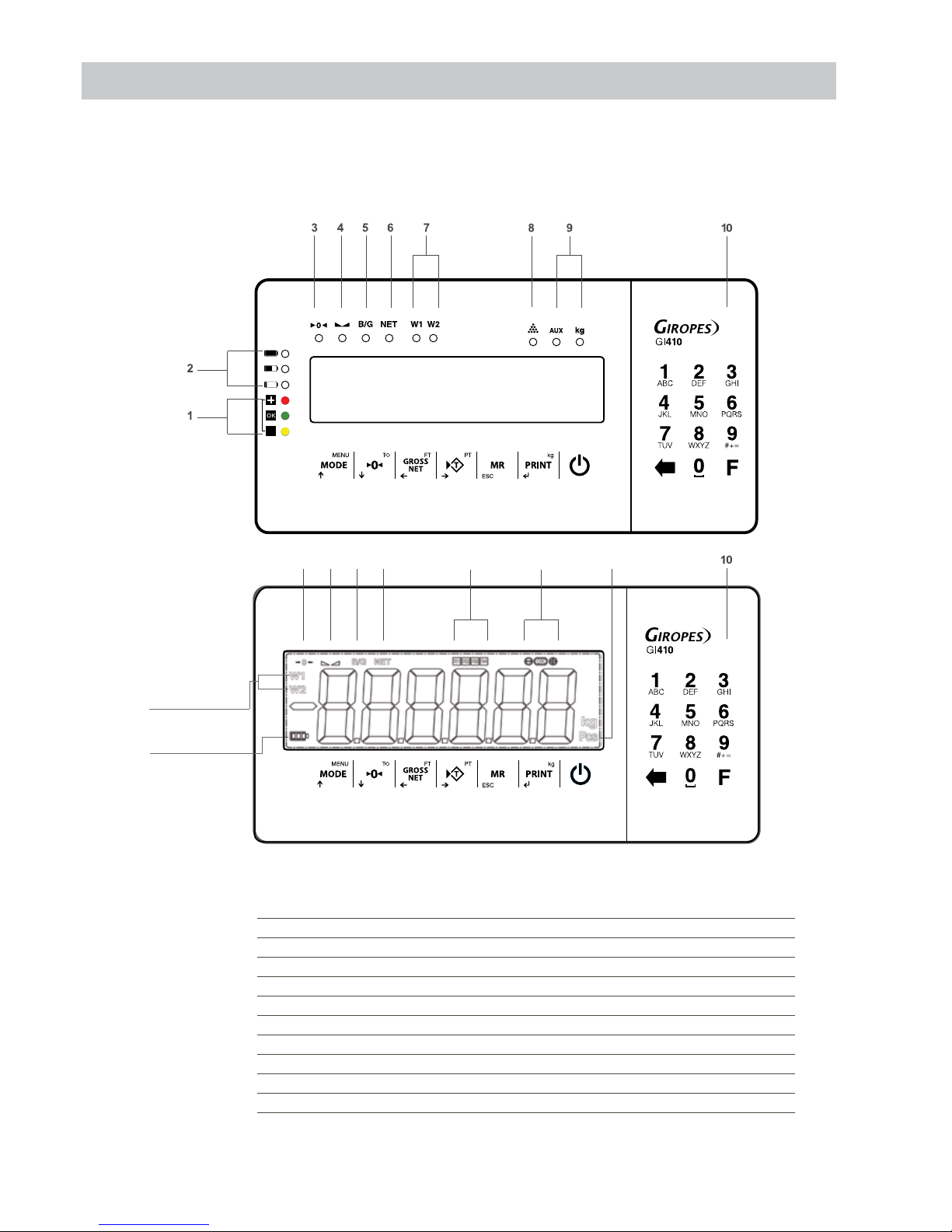
1.1 FRONT PANEL
LED
LCD
SIGNS
1 Signal of limits (checkweigher)
2 Signal of level of battery (work with battery optional)
3 Signal of zero
4 Signal of steady weight
5 Gross weight
6 Net weight
7 Weighing range
8 Piece counting
9 Units of measure
10 Numerical keyboard (only 410 models)
11 Signal of relays (only for LCD)
7
2
3 4 5 6 11 1 9 8
Page 4
ENUSER MANUAL GI400 / GI410
4
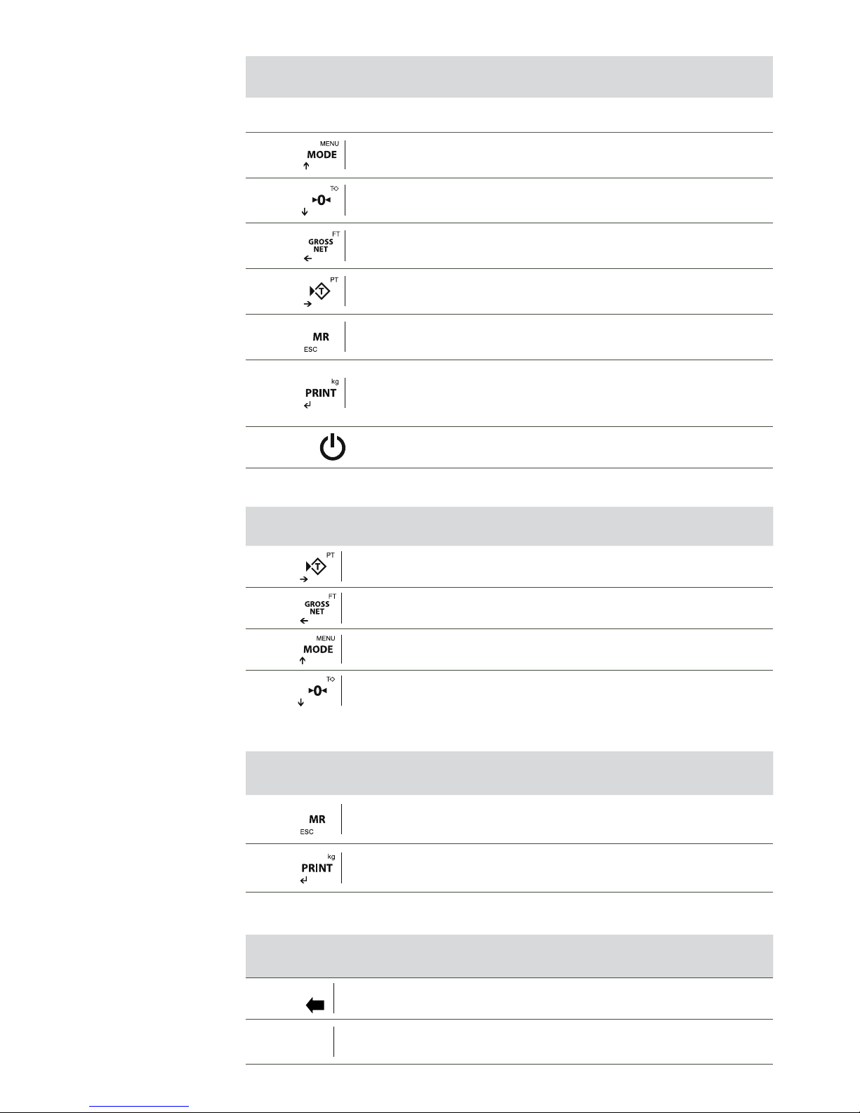
KEYBOARD
KEY DEFINITION
Short Press: Access to User Menus
Long Press: Technical Menu
Short Press: Do zero
Long Press: Remove tare
Short Press: Show Gross/Net
Long Press: Set tare
Short Press: Do the tare
Long Press: Introduce tare manually
Short Press: Weight totalization and total accumulation print
Long Press: Exit
Short Press: Print / Manual shipping weight
Long Press: Selector of unit (for lb version only), entry to the functions menu
(for other versions).
Switch on / Switch off
CURSOR KEYS (Only works in the editing menus)
Move editable digit to right side
Move editable digit to left side
Increases selected digit
Decreases selected digit
TECLAS RECHAZO Y ACEPTAR
Erase the current value
Hold down to go back.
Validate the selected value
NUMERICAL KEYBOARD (ONLY 410 MODELS)
Erase key
F
Key to change numbers to characters and vice versa.
(by pressing enter in the functions menu)
Page 5
5
ENUSER MANUAL GI400 / GI410
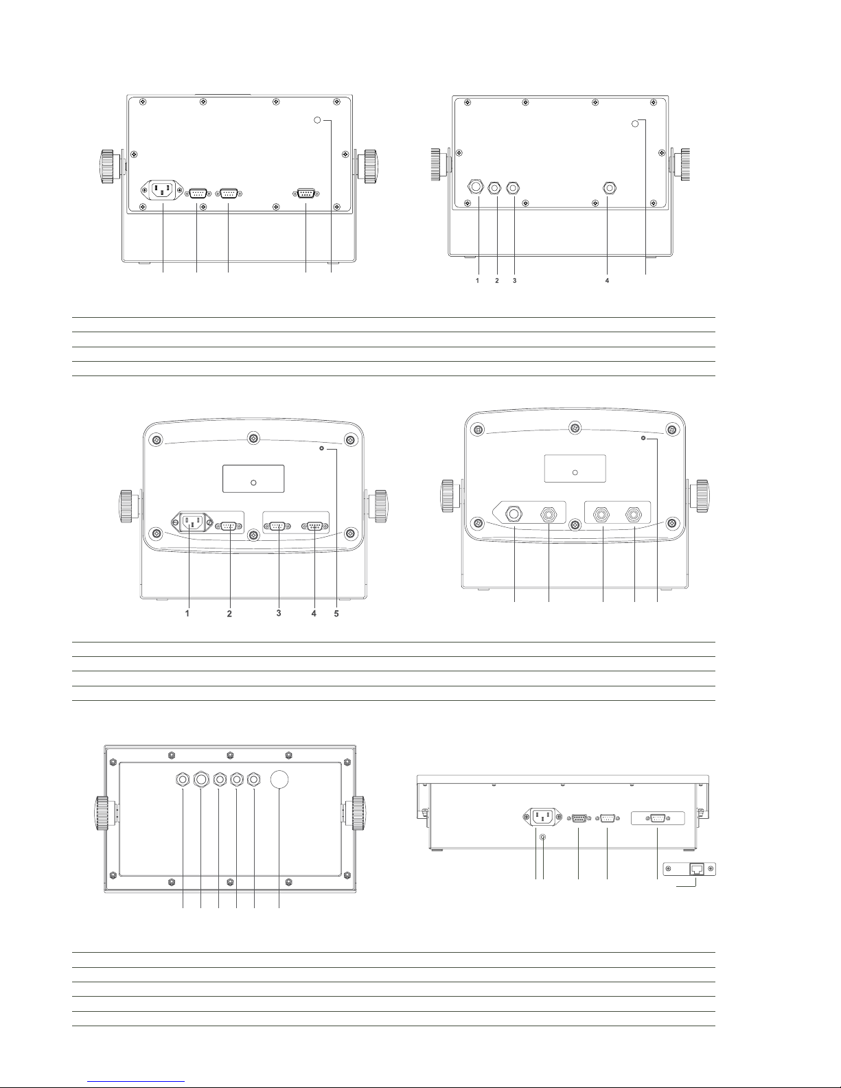
1.2 BACK PANEL
INOX IP54 INOX IP65
5
12
34
12 4
5
1 Power connector IEC PG9 for power cable
2 Connector RS232-Com1 (SubD 9 male tracks) PG7 for RS232-COM1
3 Connector RS232-Com2 (SubD 9 male tracks) PG7 for RS232-COM2
4 Connector Load cell (SubD 9 female tracks) PG7 for load cell cable
5 Calibration switch Calibration switch
ABS IP54 ABS IP65
12
34
5
1 Power connector IEC PG9 for power cable
2 Connector RS232-COM1 (SubD 9 male tracks) PG7 for RS232-COM1
3 Connector RS232-COM2 (SubD 9 male tracks) PG7 for RS232-COM2
4 Connector Load cell (SubD 9 female tracks) PG7 for load cell cable
5 Calibration switch Calibration switch
INOX IP68 GI410 PRINT
1 2 3 4 o 5
1 PG7 for additional port Power connector IEC
2 PG9 for power cable Connector Load cell (SubD 9 female tracks)
3 PG7 for load cell cable Connector RS232-Com1 (SubD 9 male tracks)
4 PG7 for RS232-COM1 Connector RS232-Com2 (SubD 9 male tracks)
5 PG7 for RS232-COM2 Ethernet Connection (opcional)
6 Pressostatic membrane Calibration switch
1 2 3 4 5 6
6
Page 6
ENUSER MANUAL GI400 / GI410
6
2. CONNECTION
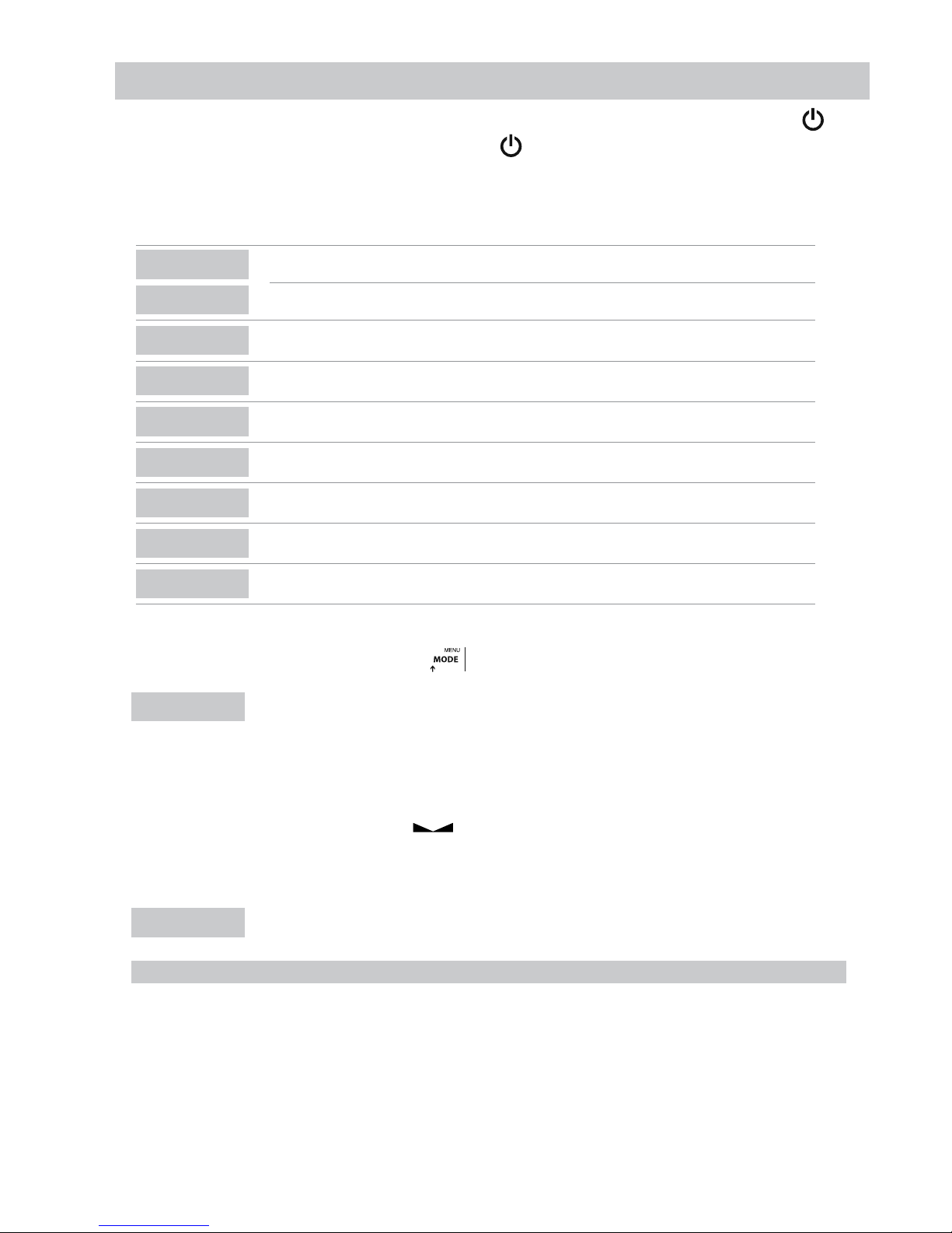
Connect the terminal to the platform through a DB9 connector. To switch on the terminal you must press for some seconds the key . To
switch off the terminal it is necessary to press for some seconds the key ; but to switch off the terminal completely it can only be done by
disconnected the terminal from the electrical connection.
2.1 TEST PHASE
DISPLAY
DESCRIPTION
In first place it appears the model of the equipment. (
91410
=GI410) o (
91411
=GI411)
91410 o 91411
LO.003
Next it will show the version of the program
8.8.8.8.8.8
Then it will appear all LEDs and display segments turned ON. (only LED version)
u1.010
After that appears the version of the user’s software
9rAvEd
This is followed by the message
9.804
Then displays the value of gravity set
n calib
Then the message number of calibrations, followed by the corresponding value appears.
9 3.008
Firmware Internal version
p x.xxx
Finnally it appears on the screen the weighing software version
2.2 DISPLAY OF THE SERIAL NUMBER
If during the phase of test display the user presses the key the device is going to show the serial number. Which you will also find printed
on the back label.
001234
2.3 SETTING THE INITIAL ZERO
When connecting the indicator it will start the setting of zero of the scale, to do so the following conditions are necessary:
1. Steady weight (luminous sign of steady weight on;
2. Weight value not less than -10% of the Max. in relation to the zero of calibration of the scale;
3. Weight value not higher than 10% of the Max. in relation to the zero of calibration of the scale.
During the development of the operation of zero setting the display is going to show the following message:
ZEro
If the weight is steady but out of the range of zero the display is going to blink for about 1 second more or less.
N.B. The user can’t do any operation until the setting of zero has been done
The precision of the setting of zero is inside and not out of the division: 0,25e
Page 7

7
ENUSER MANUAL GI400 / GI410
3. EXECUTABLE FUNCTIONS
3.1 SETTING THE SCALE TO ZER0
When the user presses the key assumes the metrological function of weight zeroing, in the modality described below, in reference to
the current regulations.
1.Steady weight (the bright sign of steady weight
is on);
2. Weight value not less than -2% of the Max. in relation to the zero of calibration of the scale;
3. Weight value not higher than 2% of the Max. in relation to the zero of calibration of the scale.
The brilliant sign indicates that the function has been done.
3.2 WEIGHT
The device switches on a led of stabilibty when a weight is placed on the platform and when the weight is steady. When the scale is unloaded
the device switches one the zero and stability leds.
3.3 TARE, SUCCESSIVE TARAS, GROSS-NET
To do a tare the user must press the key . When this key is pressed the indicator is going to show immediately the net weight, and the
Net led switches on.
If the user wants to do another tare, s/he needs to press the key again.
To know the gross weight (container plus contents) the user must press the key . On the display the led Net switches off and the sign of
gross weight B/G switches on.
If the user presses this key again the device is going to go back to the net weight and the led of Net is going to switch on again.
3.4 BLOCKING/UNBLOCKING TARE
If the user wants to block the used tare in the previous section, so that it does not disappear when going through zero, the user must press for
some seconds, at least 2, the key tare . The value of tare remains blocked. The display informs the operation showing “Tar.Blo”.
To unblock the tare the user must keep pressed 2s the key . The display is going to indicate this action by showing the message“Tar.
DES” on the screen.
To program the viewer to block the tare automatically, you have to enter the technical menu. Select “Config”, and in “Config” in “Autarb”. We
can put yes or no to the automatic tare block (“Autarb”).
3.5 MANUAL TARE
The terminal allows the incorporation of a manual tare by pressing during two seconds the key . The user must use cursor, escape and
enter keys for input new tare value. If procedure before is used, tare value will keep loocked till you unlock it.
3.6 MEMORIZED TARAS TLU
The visor has 5 memorized tares: TLU 1, TLU 2, TLU 3, TLU 4, TLU 5.
Before you can use this function you must edit and activate the desired tare from the User menu/TLU.
The tare value is locked until it is unlocked with the procedure seen in blocking / unblocking tare.
3.7 ACCUMULATION (ONLY WORKS WITH PRINT PROTOCOL ACTIVATED)
The user can not use this function without activating it first. To do it, the user must go to the menu “ModE”. To go to the menu the user must
follow the steps described in the section number 4 and watch the procedure in the section 4.6
Each time that accumulation is done, the message Acc appears on screen.
This message disappears after some seconds and it shows again the value of the last weight placed on the platform. If the user has a printer
connected to the terminal, the printer prints the weight with selected format.
Note: The accumulation can work manually or automatically
Page 8
ENUSER MANUAL GI400 / GI410
8
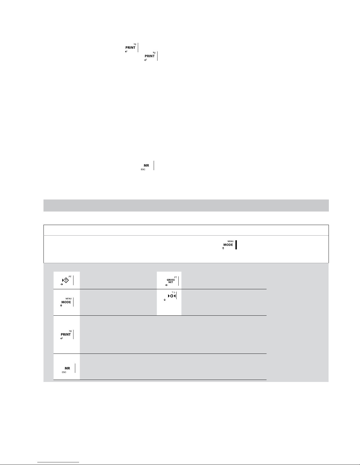
3.7.1 SUCCESSIVE MANUAL ACCUMULATIONS
Select the accumulation and printing in manual mode.
Place the weigh on the scale, press key when stable indication turns on.
If we want to accumulate again, press the key again.
The indicator will continue memorizing if: the scale has been discharged previously or tare is done or addicional weigh has been added.
3.7.2 SUCCESSIVE AUTO ACCUMULATIONS
Select the accumulation in automatic mode and enter the number of accumulations to totalize, the printing in stable, stable with zero pass or
stable to the discharge.
Place the weigh on the scale, when it takes stability it will accumulate.
The indicator will continue memorizing if: the scale has been discharged previously or tare is done or placed on the platform on additional
weight until reaching the number of accumulations programmed or totalized.
3.8 WEIGHT TOTALIZATION
If one of accumulation modes is active, once all desired weights had been accumulated and the scale is in zero the user wants to know the
total of the weights s/he must press the key . The terminal is going to show the total number of weights and the total net weight.
• If there is a printer defined in the parameters of rs232 and connected, a ticket is going to be printed.
(For ticket copies see menu “Config” / “Print” / “Copy”)
4. OPERATION MODES (USER MENU)
DISPLAY DESCRIPTION AND SEQUENCE OF USE
• The user can access to this menu once by pressing the key
• The display is going to show the message "ModE ” on the screen and next it will appear the first available function.
MODE
• The user must use the keys described bellow to select the desired function.
- Move to the right side the edition
digit.
- Move to the left side the edition digit.
- Inside a menu increases the value
of the selected number.
- It goes to the previous function.
- Scrolls to the back menu.
- Within the menu decreases the selected number
- Inside a menu, goes back
memorizing the value set.
- It selects the current function.
- If the user keeps this key pressed s/he can exit from the
function without memorizing the value set (function ESC).
- With short press, returns to zero the current value.
Page 9

9
ENUSER MANUAL GI400 / GI410
THE AVAILABLE FUNCTIONS ARE:
CAL AUU
CALCULATION OF THE AVERAGE UNIT WEIGHT
AUU
PIECE COUNTING
CHECt
CHECKWEIGHER
CCt SI
CHECKWEIGHER SIMPLE
by 10
IT SHOWS THE WEIGHT WITH ONE MORE DECIMAL FOR MORE ACCURACY
ACCUMU
ACCUMULATION
Subtot
SUBTOTAL
t CodE
SET PRODUCT CODE
n tiC
SET TICKET NUMBER
WEIGHt
WEIGHT MODE
doSiFi
DOSAGE (only with additional board 4I/40 (relay) (OPTIONAL)
LiMit
LIMITS (only with additional board 4I/4O (relay) (OPTIONAL)
2 rEL
ZERO AND WEIGHT (only with additional board (relay) OPTIONAL)
dSd
FISCAL MEMORY (only with additional board ALIBI) (OPTIONAL)
tLU
MEMORIZED TARAS TLU
AnALog
ANALOG OUTPUTS (Only with analog board OPTIONAL)
FUnCio
FUNCTION MODE
4.1 CALCULATION OF THE AVERAGE UNIT WEIGHT CAL AUU
This function calculates the unit weight of the pieces through the piece counting program. To calculate the average unit weight the user must place a number of known pieces on the platform and the press the key . The screen of the display is going to show the message SP.xxxx.
The user must then introduce, using the keys, the number of pieces that make the sample.
To calculate and register the value of the average unit weight the user must press the key .
The terminal shows- during two seconds- the message “WEiUni” on the screen, followed by the unit weight of the piece. After that, the indicator
goes back and shows the number of pieces in the scale.
If the user presses the key and there is no weight on the platform or the weight is inferior to the necessary to calculate it on the screen,
the display is going to show the message “add”. This message indicates that more pieces are needed so that the calculation can be done.
4.2 PIECE COUNTING AUU
This function is used to do the calculation of the pieces loaded on the platform. It does so by taking the programmed average weight (PMU).
The indicator asks for the PMU by showing the message Px.xxxx. The user must introduce the value of the unit weight using the cursor keys.
Press key to confirm.
NOTE: The parts count mode remains active until we access the weight mode.
4.3 CHECKWEIGHER CHECt¡
This function activates the mode “CHECK WEIGHER” or mode goes-not-goes .
The equipment is ready to manage automatically up to 4 zones through limits of weight for each one of them.
When the user accesses the menu CHECt the first parameter s/he must configures is the menu tArgEt: this menu programs the value of the
target of weight that the user wants to achieve. Is the central value of OK zone.
After that the user must choose the type of TARGET between TTYPE1 and TTYPE2.
Page 10
ENUSER MANUAL GI400 / GI410
10
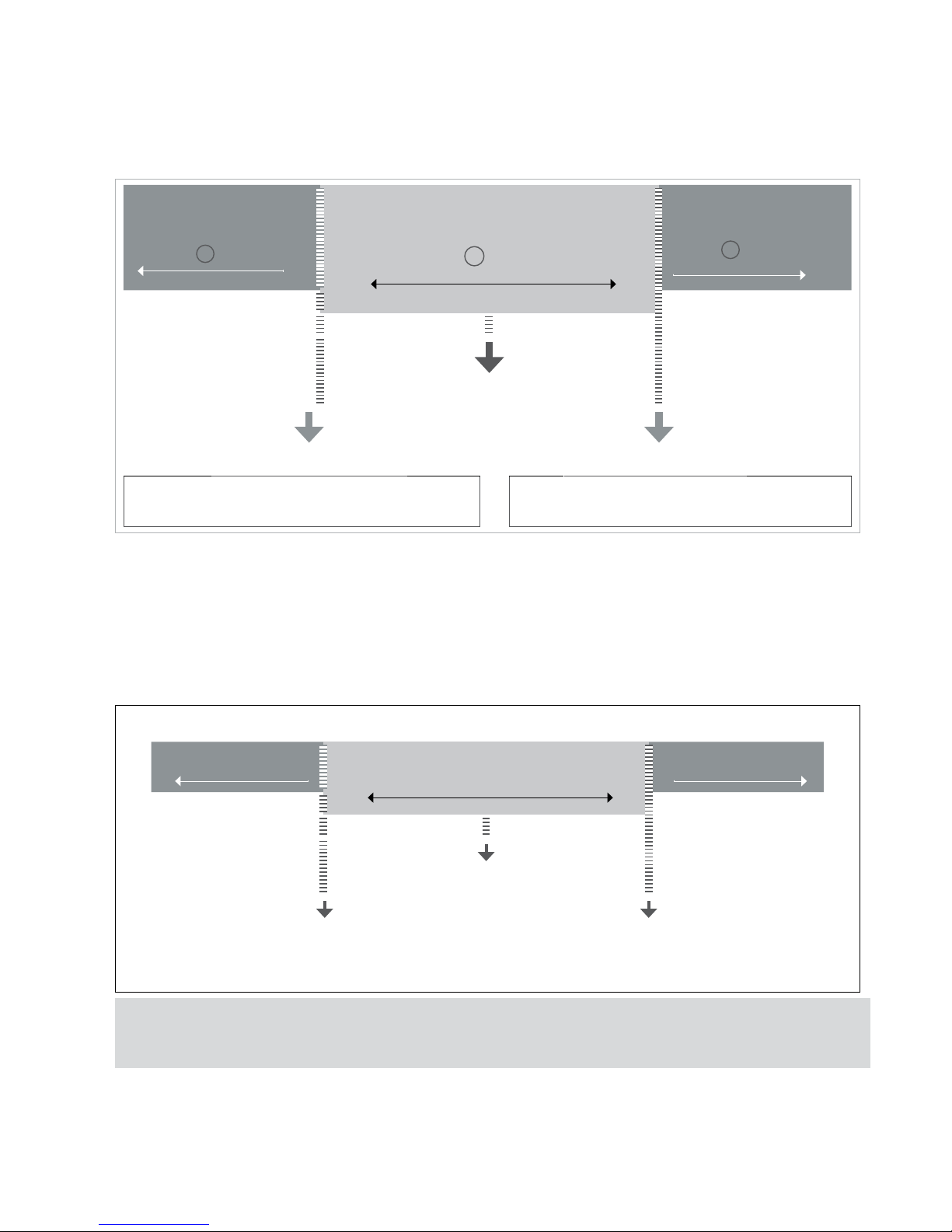
4.3.1 TARGET TYPE 1
T.TYPE 1
If the user chooses the T. TYPE 1 it allows to choose the inferior limits and the superior ones with a porcentage of the TARGET value.
Exemple:
-PC. 010 (We chose how lower limit 10% below the Target)
PC. 010 (We chose how upper limit 10% above the Target)
LOW
LED: yellow LED
LCD: - Yellow backlit
OK
LED: green LED
LCD: OK green backlit
HIGHT
LED: red LED
LCD: + red backlit
TARGET 1000 g
HOW LOWER 900 g
UPPER LIMIT 1100 G
HOW LOWER = target -10% of Target=
1000 - [10%(1000)]=900
UPPER LIMIT = target +10% of Target=
1000 + [10%(1000)]=1100
4.3.2 TARGET TYPE 2
T.TYPE 2
If the user chooses the
T.TYPE 2
, it allows to choose the inferior and superior limits directly: L (lower)
XXXXX
y H (Hight)
XXXXX
Exemple:
L 800
H 1200
LOW
OK
HIGHT
TARGET 1000 g
HOW LOWER 800 g HIGH LIMIT 1200 g
Once they are configured, the TARGET value and the LIMITS, the program ask the user to configure the limit of the ALARM.
The alarm programs the value wich any value above this one is going to activate the alarm sign, and 3 lights are going to bright.
Finally the user must choose the alarm sound. He can choose between bEEPt or bEEPM.
Page 11

11
ENUSER MANUAL GI400 / GI410
4.3.3 TYPE BIP
bEEPt
First we choose the area in which we want the beep to sound, this will occur when entering the selected zone:
no tAr
: When it’s not in the target range.
LoU:
Below the target range.
tGtrnG
: Target range.
HiGH
: Above the target range.
4.3.4 BIP MODE
bEEPM
Then choose the kind of beep: B off/long/short
4.3.5 YES/NO ACTIVE
Finally asks us if we want or not to activate the function checkweigher, in the case of not activating it is memorized the configuration that
we have chosen previously.
Note: The Checkweigher mode remains active until we access the weight mode
4.4 CHECKWEIGHER SIMPLE
CCt SI
This function activates the “CHECK-WEIGHER SIMPLE” mode or simple pass-not-pass mode. In the case of having indicators with numeric
keypad, we can also activate it through F + 9 + 9
The device is prepared to automatically manage up to 3 zones by two weight limits.
When accessing the
CCt SI
menu the first parameter to be configured is the lower limit. The screen briefly shows InF: and remains showing
L00000
. With the cursor keys or the membrane keyboard, we enter the value of the lower limit and validate with
The screen will briefly shows SuP: and remains showing H00000. With the cursor keys or the membrane keypad, we enter the value of the upper
limit and validate with
The screen briefly shows CWS.on and returns to weighing mode with the simple checkweigher function activated
Note: Simple checkweigher mode remains active until we access the WEIGHT mode. In the case of having indicators with numeric keypad, we
can also deactivate it by pressing F + 9 + 8.
4.5 IT SHOWS THE WEIGHT WITH ONE MORE DECIMAL MORE FOR ACCURACY bY 10
With the selection of this function the indicator displays one more decimal in the weight.
Once this function is authorized there is an activation of the display. In this situation the less significant number of the display gets activated and
it indicates the value per 1/10 of the division of the verification. The decimal moves but the display does not increase a digit.
With the device connected, the display of the data of weight does not respect the metrological indication. It is for this reason that while it is
activated all the communication with the series channel is inhibited. The display remains active for a period of approximately 6 seconds, after
this time the terminal, automatically, sets the display in normal weight. Being out of legal metrology, the device keeps extra accuracy till user
press
key.
Page 12
ENUSER MANUAL GI400 / GI410
12
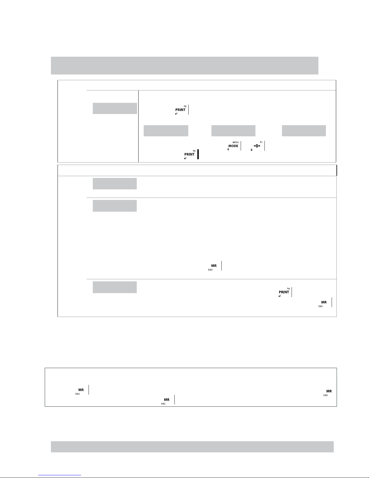
4.6 ACCUMULATION ACCUMU
This function carries out the process of auto accumulation and ticket printing
TO MAKE THE AUTO-ACCUMULATION FUNCTION WORK, IT IS NECESSARY TO SELECT FIRST THE PROTOCOL PRINT IN COM1
OR COM2, AS IT IS DESCRIBED IN THE SECTION 5 “PARAME” (POINT 6.1)
DISPLAY
STEPS
ACUMUL
• Press the key
the display is going to show one of the legends detailed below.
ACUMUL
ACCoFF ACCMAn ACCAUt
The user must choose them with the keys and , the selected option is memorized
by pressing the key .
DESCRIPTION: ACCOFF, ACCAUT AND MANACC, AND CONFIGURATION
ACC.oFF
ACUMULAR OFF
The accumulation mode is deactivated
ACC.AUt
AUTO ACCUMULATION
The accumulation mode is automatic. In the moment of detecting steady weight the device does
the accumulation automatically. Once this function is validated the terminal shows on its display
the message (nA xxxx). The user must introduce the desired value of the number of accumulations using the following keys:
If this value is DIFFERENT FROM 0 the system continues with the accumulation of weights until
it reaches the prearranged value. If the programmed value is 0, the weights are accumulated until
the user decides to press the key (limit 9999). (Totalitzation)
ACC.MAn
ACCUMULATION MANUALLY
The mode of accumulation is done manually by pressing the key .The weight must be
stable and must change from accumulation before. It will accumulate till the user press .
4.7 SUBTOTAL SUBTOT
With this function the user can see the number of accumulated weights and the total weight up to the actual moment. The screen displays first
the number of weights and next it automatically shows the total accumulated weight. This function does not entail the elimination of the number
of weights and the total of weight.
4.8 TOTALITZATION
By pressing key device shows totalitzation value. If one printer mode is selected, the total ticket will be printed. By pressing again
key will print a copy. Making a new accumulation after the memory will be erased.
4.9 CODE TCODE
This function allows the introduction of a code which is added to the printed ticket. To introduce this code the user must use the keys specified below.
THIS OPTION IS ONLY VALID USING PROTOCOL PRINT WITH THE OPTION PrnF.4 OR PrnF.6 ACTIVATED.
Page 13
13
ENUSER MANUAL GI400 / GI410
4.10 NUMBER OF TICKET NTIC
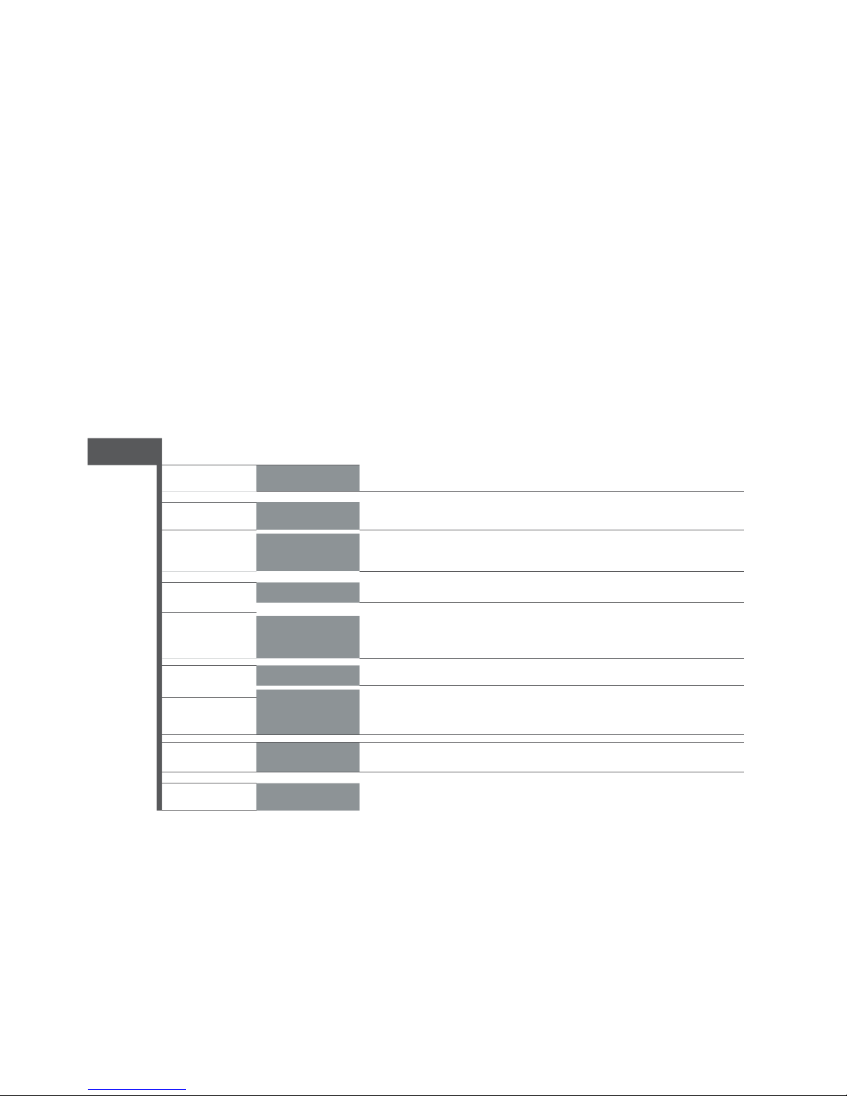
With this function the user can print in the ticket a ticket number which is going to increase automatically at the end of the weight, (number of
delivery or number of ticket). Use the cursor keys for change the value and enter escape to exit or memorize..
4.11 WEIGHT MODE WHEiGt
The user access the normal mode of weighing again.
4.12 DOSAGE dOSIFI
PRECISE PLATE ADDED 4I/4O(relay)
With 4 inputs and 4 outputs. The dosing function is only available when the plate is correctly connected to the display.
The card has four relays with potential-free output up to 0.5A 125VAC or 2A 30VDC. With them you can check remote instruments such as relays, signal
lamps and PLC. The card also has four inputs. The 4 inputs are emulated to the keys of the equipment when they are in dosage mode. The dosing function
remains active until it is switched off.
The equipment is ready to dose automatically with two different possibilities: 1 product at two speeds or 2 products at one speed, with unload. The device
allows the pogramming, for each porduct, of the weight of the value of the thickness or product 1, and the value of the weight when the device works at
slow speed (that is the value of the smooth) or the value of the product 2.The device can also program a zone of unload where it is defined the value of the
dosage( to correct the blocking of the system because there is product left in the weighing zone).
When the equipment starts working it automatically functions with the last formula it has worked with. This allows the device to start again with its daily work.
When the user gets into the menu to program the dosage “doSiFi”, the following menu is going to appear on the screen:
doSiFi
reset
YES / NO yes-no (It sets the process to zero, it also places all the weights to ZERO)
Prod1 W
WEIGHT thick weight to program or weight of the product 1
Prod1 t
TIME
time of lack of material, if the weight on the screen does not change in this space of time,
it activates the relais of alarm.
Prod 2W
WEIGHT smooth weight to program or weight of the product 2
Prod 2t
TIME Time of lack of material
2 discw
WEIGHT Maximum waste weight
TIME
Time of zero, when the zero is activated a time to wait for the falling of the material
is also activated
2 disct
tArEC
AUTO/NO
Make, or not, auto tare when dosage starts
EnAbLE
YES / NO
RESET
By selecting YES, all parameters are set zero.
By selecting NO, you can access directly to the parameters to modify them.
PROD1
It edits the values of the formula for the product 1. If the weight is programmed to 0, the equipment is going to dosify the product 2.
•
W
(Weight): The desired weight for this product is programmed.
• T (Timer): Time of lack of material, if the weight on the screen does not vary in this space of time, it is going to activate the alarm (RL4)
PROD2
It edits the values of the formula for the product 2. If the weight is programmed at 0, the equipment will dosify only the product 1.
• W (Weight): The desired weight for this product this product added to product 1 weight is programmed.
• T (Timer): Time of lack of material, if the weight on the screen does not vary in this space of time, it is going to activate the relais of
alarm. (RL4)
Page 14
ENUSER MANUAL GI400 / GI410
14
Z.DISC
•
W
(weight): This option programs the weight within which the equipment determines that the dosage has been finished, (maximum of
possible waste weight that may stay without the alarm ringing)
• T (timer): Time waste of material, if the weight on the screen does not vary in this space of time, it is going to activate the relais of
alarm (RL4).
ENABLE
It exits from the menu of dosage and asks to the user if he wants to get start doing the dosage. To start doing the dosage appears on the
display the legend
- dos ON -
The keys will do the functions specified below:
Note:
The value of timers must be bigger than 000,0 s. for assure the capacity of activate the alarm (RL4). If you want that
RL4 (alarm) will never be activated, keep timers to 0s.
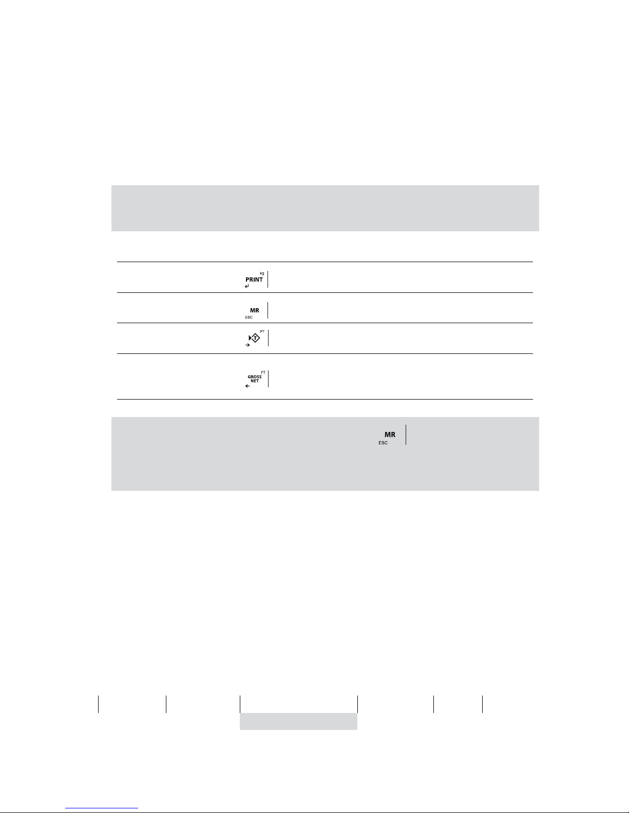
ENTRANCE EXT. KEY INDICATOR FUNCTION
INPUT 1
START key
INPUT 2
STOP Key
INPUT 3
RESTART key
INPUT 4
ABORT key / exits from the DOSI function and goes back to
the normal mode. You need to press two times if you use the
indicator key.
Note: In the event that the alarm relay (RL4) is activated, press the key and then restart key to continue the
process where it was interrupted.
To dispense a single product, it is necessary to leave the Prod 1W to 0 and set the weight to be dosed in the Prod
2W
4.13 LIMITS LIMIT
THEY ONLY WORKS WITH THE OPTIONAL RELAYS BOARD
The equipment is able and thought to manage automatically up to 4 limits through registers of weight for each one of them.
These registers are called
• Start
• Low Limit (Low.L.)
• High Limit (High. L.)
• Alarm
The associated relays is always activated when the weight of the scale is placed between the two limits.
0
Start
i
Low limit
nf (inferior)
High Limit
Alarm
OL
relés OFF RL 1 RL 2 RL 3 RL 4 relés OFF
OK
As each relay is in fact a commute circuit, taking the normaly closed contacts, the user is going to obtain the inverse sign of the previous figure. When we go to the function of the programming of limits (
LiMitE
), the following menu is going to appear on the screen:
Page 15
15
ENUSER MANUAL GI400 / GI410
DISPLAY
RESET
SI Goes to next parameter without erase the information.
It places at 0 all the relays so that it deactivates all of them.
NO
START It programs the value, every value above this one is going to activate the relays of the L.INF, RELAYS 1 (S
xx.xxx)
L.LoU
It programs minimum value, every value below this one is going to activate the relays of the L:INF, RELAYS 1
(L xx.xxx)
OK
This value can not be programmed but it activates the RELAYS 2 whenever the value of the weight is superior
to Low L and inferior to the High L
HiGH
It programs the high value, every value above this one is going to activate the relays of the L.SUP, RELAYS 3
(H xx.xxx)
ALARM it programs the high value, every value above this one is going to activate the relays of alarm, RELAYS 4 (A
xx.xxx)
ENABLE
Exit from the menu limits and start to apply them if YES is choosed. If we choose NO exit from the menu and
doesn’t apply the limits stored on memory.
NOTES: THE FUNCTION OF THE LIMITS IS AUTOMATIC WHEN IT EXITS FROM THE ZERO RANGE. THE LIMIT
FUNCITON CONTINUES ACTIVATE TILL USER DESACTIVATES IT.
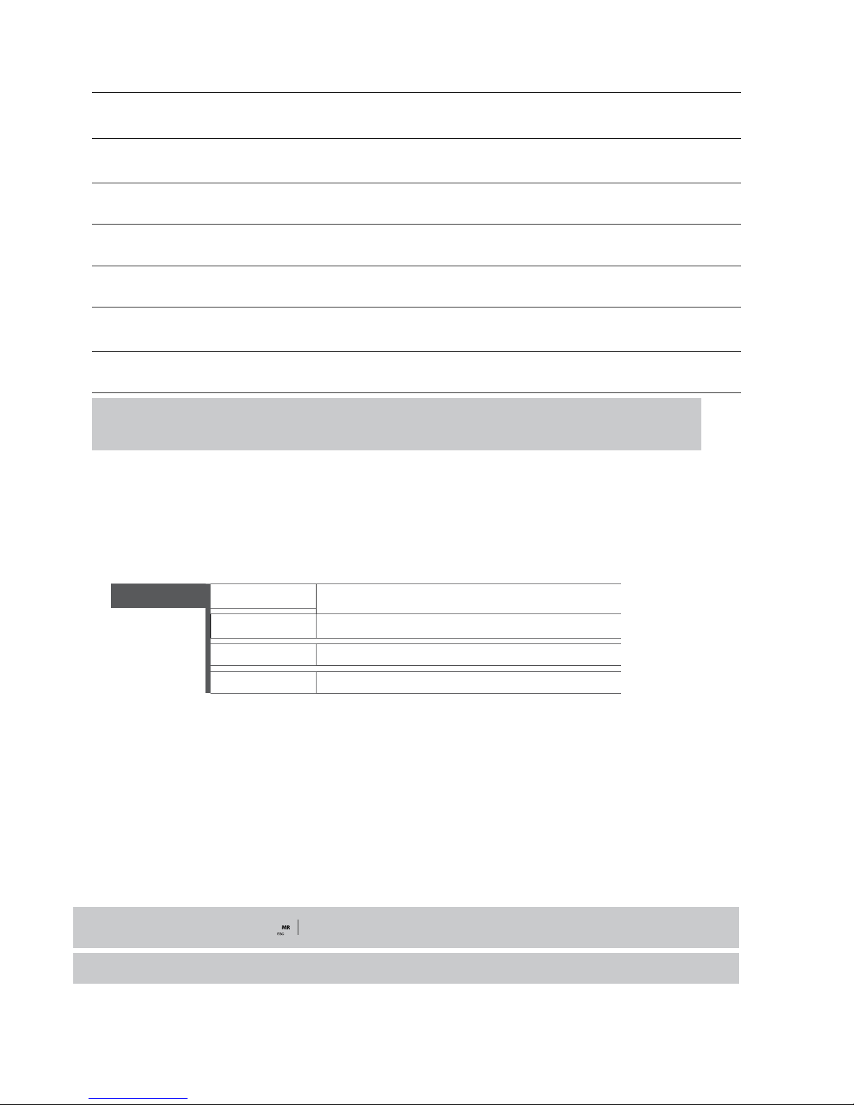
4.14 ACTIVITY CONTROL 2 rEL
REQUIRES ADDITIONAL PLATE 4E/4S(relés)
It is a variant of the limit function, but involving only two relays, deactivating the first when exiting the value “Starts" and the second disengaging once we reach the value "target"
2 rEL
rESEt
Select Yes/No to restore values to 0..
Start (00,000)
Deactivation Value 1st Relay
target (00,000)
Deactivation Value 2nd Relay
EnAbLE
Select Yes/No to activate the function
4.15 DATA VISUALISATION MEMORIA dSd
• Accessing to DSD menu (only available if DSD memory is installed) the indicator give access to DSD file to see the weights stored with
fiscal memory process.
• The indicator will show the last code inuse, with cursor keys you can input the desired value.
• On last line it shows the current weight.
• Then, operator must input the weighing number about he/she want fet data of brut and tare.
• If data is not stored, it will show an error message, if all is correct, it will show weighing data.
For exit from data menu, keep pressed key some seconds.
During data viewing “Tx” function from PC will not work.
Page 16
ENUSER MANUAL GI400 / GI410
16
4.16 MEMORIZED TARAS TLU tLU
• The visor has 5 memorized tares: TLU 1, TLU 2, TLU 3, TLU 4, TLU 5.
• Before you can use this function you must edit and activate the desired tare from the user menu/TLU
• The tare value is locked until it is unlocked with the procedure seen in lock/unlock Tare.
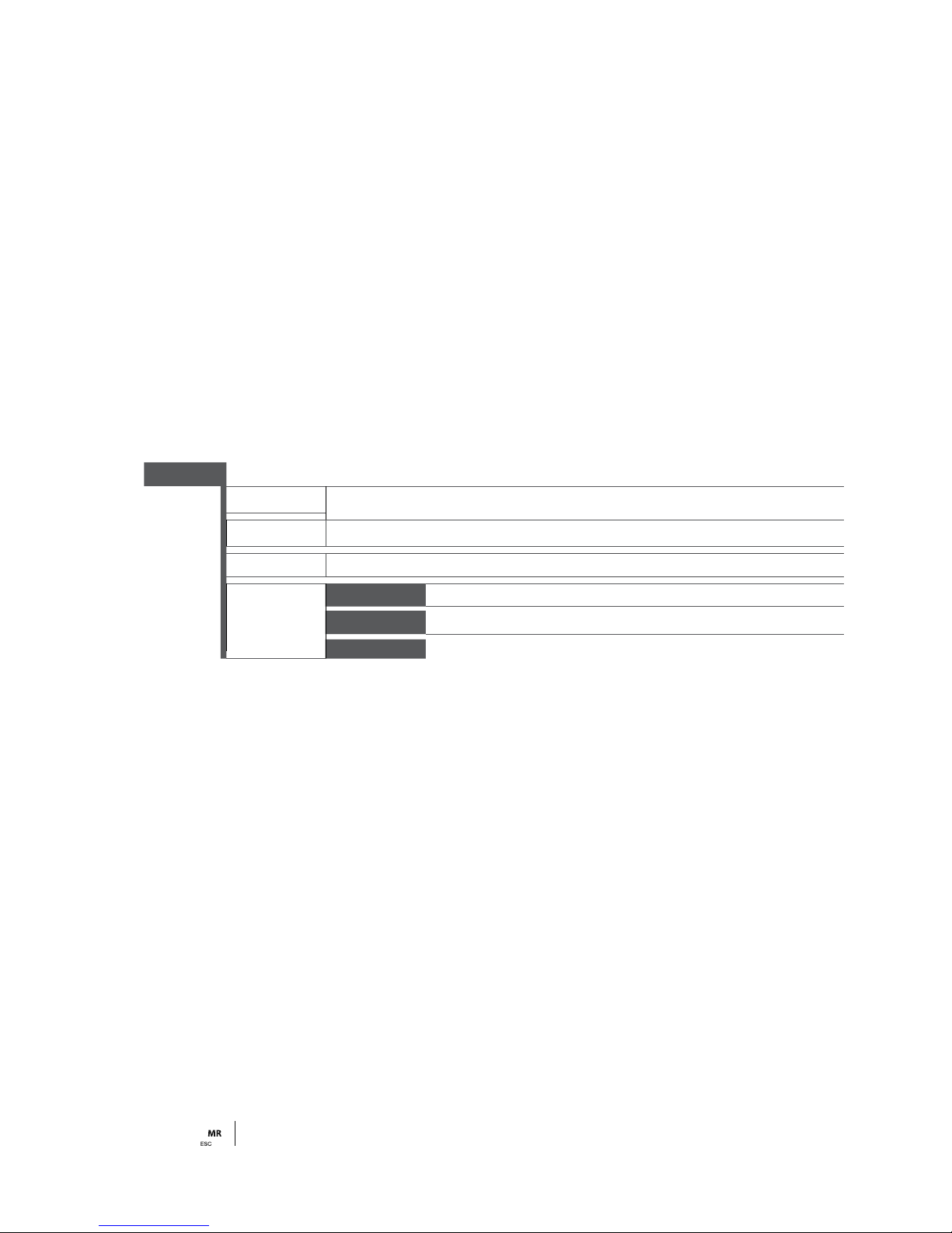
SELECT: To select the tare that we want to activate, this has to be previously created in the editing section
EDIT: To create the tares up to a maximum of 5.
DELETE: To erase all memorized tares.
4.17 ANALOG OUTPUT (ONLY FOR LED DEVICES!) AnALoG
ACCESS TO THE MENU IS POSSIBLE ONLY WHEN THE CARD IS CONNECTED
This card allows the exit of 4-20mA o 0-20mA or 0...+10V o 2…+10V, proportional to the gross weight or the net weight in the scale.
The exit of the current is active and supplies the necessary voltage.
The analog exit is actualized every 50ms and acquires the appropriate value of the weight, converted into in that moment. It is for this
reason that if the filter in the weight is decelerated, the analogical exit is also decelerated.
To do the setting of the parameters, the user must access to:
AnALog
ActivA
Select Yes/No to turn functionality on or off
4-20mA
Requesting full scale (P. MAX) in kg that will deliver 10V.
0-10V
REQUESTING FULL SCALE (U MAX) IN KG THAT WILL DELIVER 10V.
ADJUST
An Min Output for negative weight
An.Zer
Output for zero weight
An MAX Departure for the fund allocated scale (U MAX)
We have to activate the
AnALog function before we start setting
The setup process begins by selecting the operating mode, either 4-20mA or 0-10V depending on the type of output you want. At this point
you must specify the full scale U MAX which must be equal to or less than the full scale of the scale.
When the back of the scale is confirmed, the device starts the establishment of values of the analog exit, or the values of the digital/analog
converter are introduced (comprised between 0 and 65535), for these values it is appropriated a determined value of exit in voltage or
current.
In this configuration the keys of the device acquire the following functions:
An Min ( N. xxxxx)
It establishes the minimum value of the analog exit. With this value we adjust so that the equipment gives a value below 4 mA or 0v. It
also allows us to program the magnitude of the signal when the value loaded on the platform is below zero, belonging to the condition
underload.
An.2 Er( z. xxxxx)
It establishes the magnitude of the analog exit, be that in current or voltage, when the scale displays the minimum weight, which is
going to belong to the Zero of the scale.
An MAX ( M. xxxxx)
It establishes the magnitude of the analog exit, be that in current or voltage, when the scale displays the maximum weight, which is
going to belong to the previous FS programmed.
Press to access the menú ACTIVA.
Page 17
17
ENUSER MANUAL GI400 / GI410
EXAMPLE
We are going to take as example a hopper scale with a back of scale of 300kg. Of this scale we only use the range up to 200kg for the exit
of 20mA as this is the maximum capacity of the hopper.
In F.S we will introduce 200kg and we will adjust the value of An_Max so that in the exit we can register 20mA with a multimeter or an
automaton. Next we are going to go to the parameter An_Zer and adjust the value to obtain 4mA in the exit; with this we are going to have a
perfect measuring range of 200kg and 16mA. In the parameter An_Min we are going to introduce a value so that we can read the negatives
to up to the 3mA. In the case that the automaton does not allow it, we will adjust the zero to 5mA. The measuring range is going to be of
200kg and 15mA.
4.18 FUNCTION MENU FUnCio
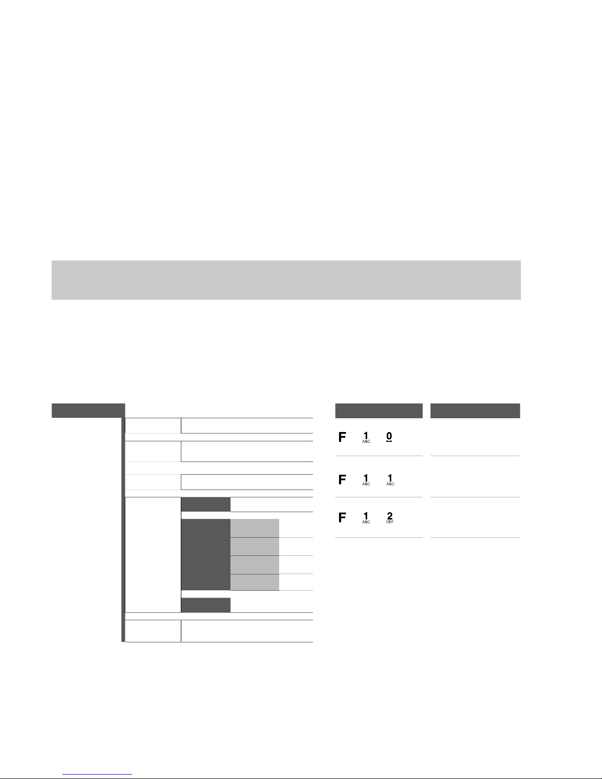
It is a mode of operation of the user menu. In the next stitch (5. Special functions of the numeric keypad) It is explained, from the operation
of the numeric keypad viewfinders, how this mode works.
The diagram of the left side would be common for all the viewers, and in the detail the operation of each section to manage, items of
weighing, descriptive items, tares and heavy, navigating the menus with the keys with arrows enter and ESC.
5. SPECIAL FUNCTIONS OF THE NUMERICAL KEYBOARD
(FOR MODELS WITH KEYBOARD)
You can enter the following menu by pressing and holding the F key. You can also access each function directly using the direct keys.
The numeric keypad allows us to enter the values of the different menus of the viewfinder much faster than with the keys with arrows, which
still continue working.
Using the numeric keypad it is possible to memorize a maximum of: 400 items of type of weighing (File1), 400 descriptive items (File2),
10 tares and 1000 weight.
Pr. File 1 Filxxx (Select File 1) DIRECT KEYS FUNCTION
CODE
XXXXXX
+ +
Edit item1 menu
DESCRI
24 alphanumeric characters
+ +
Activates the item 1
TARA
TXXXXX
TYPE
WEIGHT
+ +
Deactivates the item 1
CHECKW
TARGET TXXXXX
LOW LXXXXX
HIGHT HXXXXX
ALARM AXXXXX
AUU
PXXXXX
EANCODE 12 alphanumeric characters (NO FUNCTION)
Page 18
ENUSER MANUAL GI400 / GI410
18
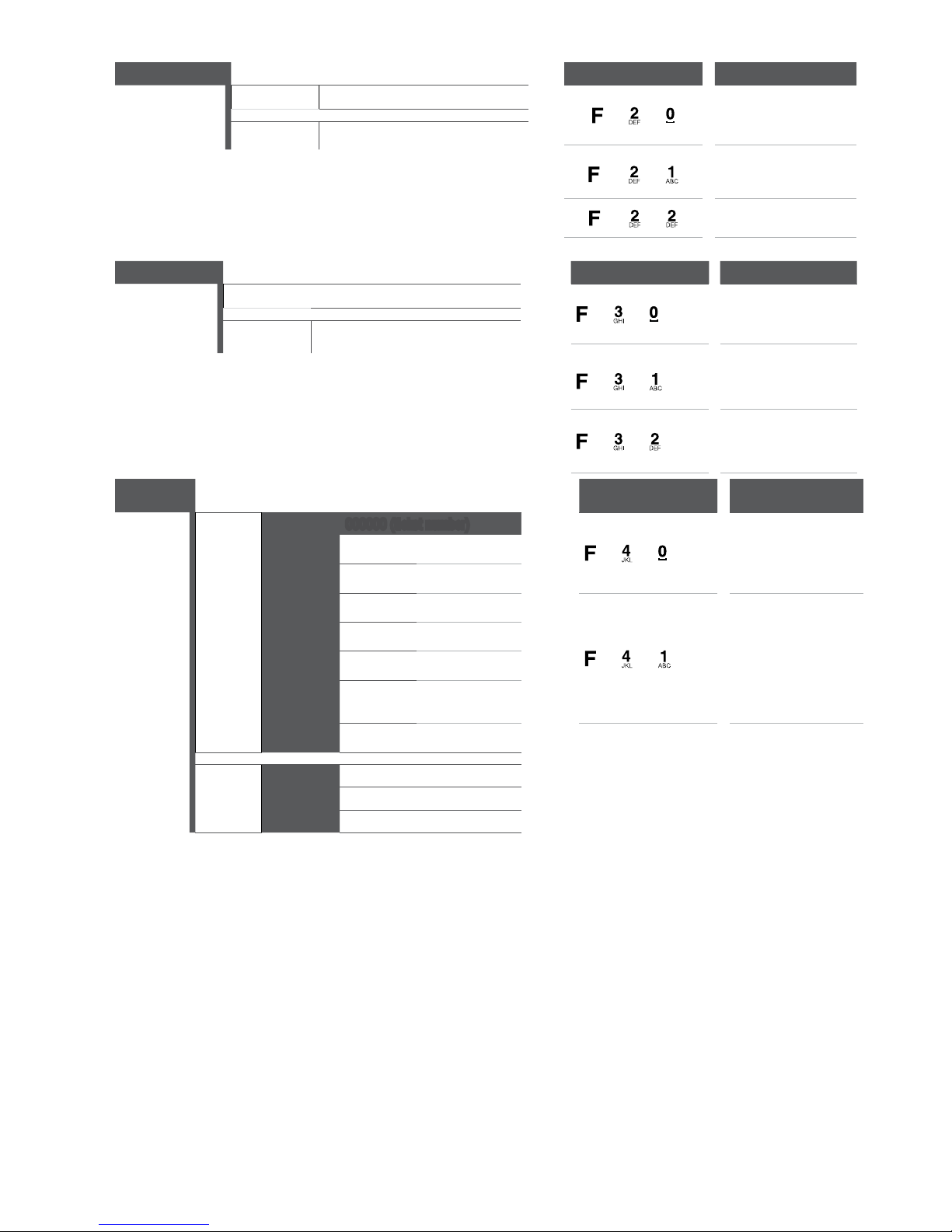
Pr. File 2
Filxxx (Select File 2)
DIRECT KEYS FUNCTION
CODEE
XXXXXX
+ +
Edit item 2 menu
DESCRI
24 alphanumeric characters
+ +
Activates the item 2
+ +
Deactivates the item 2
PrTare Select tare Number or edit DIRECT KEYS FUNCTION
TARAXX
+ +
Edit pretare menu
TXXXXX
+ +
Activates tare
+ +
Deactivates tare
WEIGHT
DIRECT KEYBOARDS UNCTION
VISUAL inUnun
000000 (ticket number)
+ +
Displays the
information of the
weights
IT1num
IT2num
W Net
+ +
Sets the type of warning
when filling out the 80%
of the weighing buffer.
When reaching the 100%
the indicator displays the
error message OveBuf
W Brut
W Tare
N Piece
DATE
CONFIG (BFULLX) 0 No warning
1 Bip
2 Bip+ BUFFULL Message
Page 19
19
ENUSER MANUAL GI400 / GI410
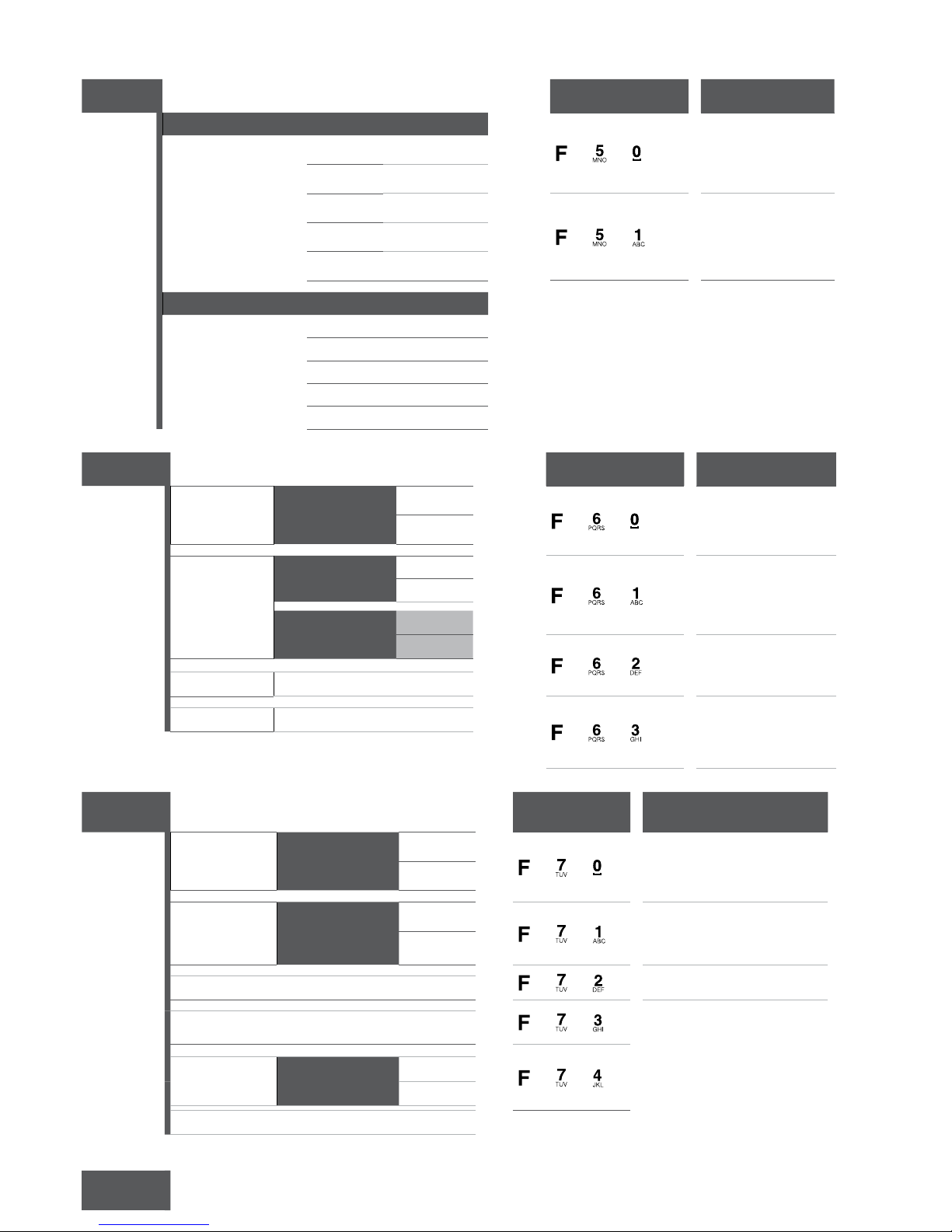
TOTAL
DIRECT KEYS FUNCTION
FILE 1 Filxxx
+ +
It shows the total of the
weighing associated to
the item 1
Net
Gross
Tare
+ +
It shows the totals of
the weighing
associated to the item2
Pieces
TotWeigh
FILE 2 Filxxx
Net
Gross
Tare
Pieces
TotWeigh
LIST
DIRECT KEYS FUNCTION
TOTAL E
SinBor
+ +
Prints the weight total
with or without deleting
the memory
ConBor
FILTRO IT1XXX
+ +
Prints the lists of the
filtered weighing, per
item 1, item 2 and date
IT2XXX
DATENO/DATESI
INICIO
FIN
+ +
Prints the filtered
information per item 2
FILE 2
Filxxx
+ +
Prints the filtered
information per item 1
FILE 1
Filxxx
DELATE
To access the erasing functions it is necessary to enter a
password, by default 0000
DIRECT KEYS FUNCTION
FILE1 FilXXX
ALLIT1
+ +
Deletes item by item the totals of
the item1 selected (TOTIT1) or
the item1 completely (ALLIT1)
TOTIT1
FILE2 FilXXX
ALLIT2
+ +
Deletes item by item the totals of
the item2 selected (TOTIT2) or
the item2 completely (ALLIT2)
TOTIT2
+ +
Deletes a tare scheduled before
TARAPR TARAXX
+ +
Deletes the stored table of
memorized weighing
WEIGHT
+ +
General deleting, it deletes all
the information in item1, item2,
tares and table of weighing.
GENERATES
NO
YES
CAPASS Change the password
SELECT Allows us to activate the memorized items or tares
Page 20
ENUSER MANUAL GI400 / GI410
20
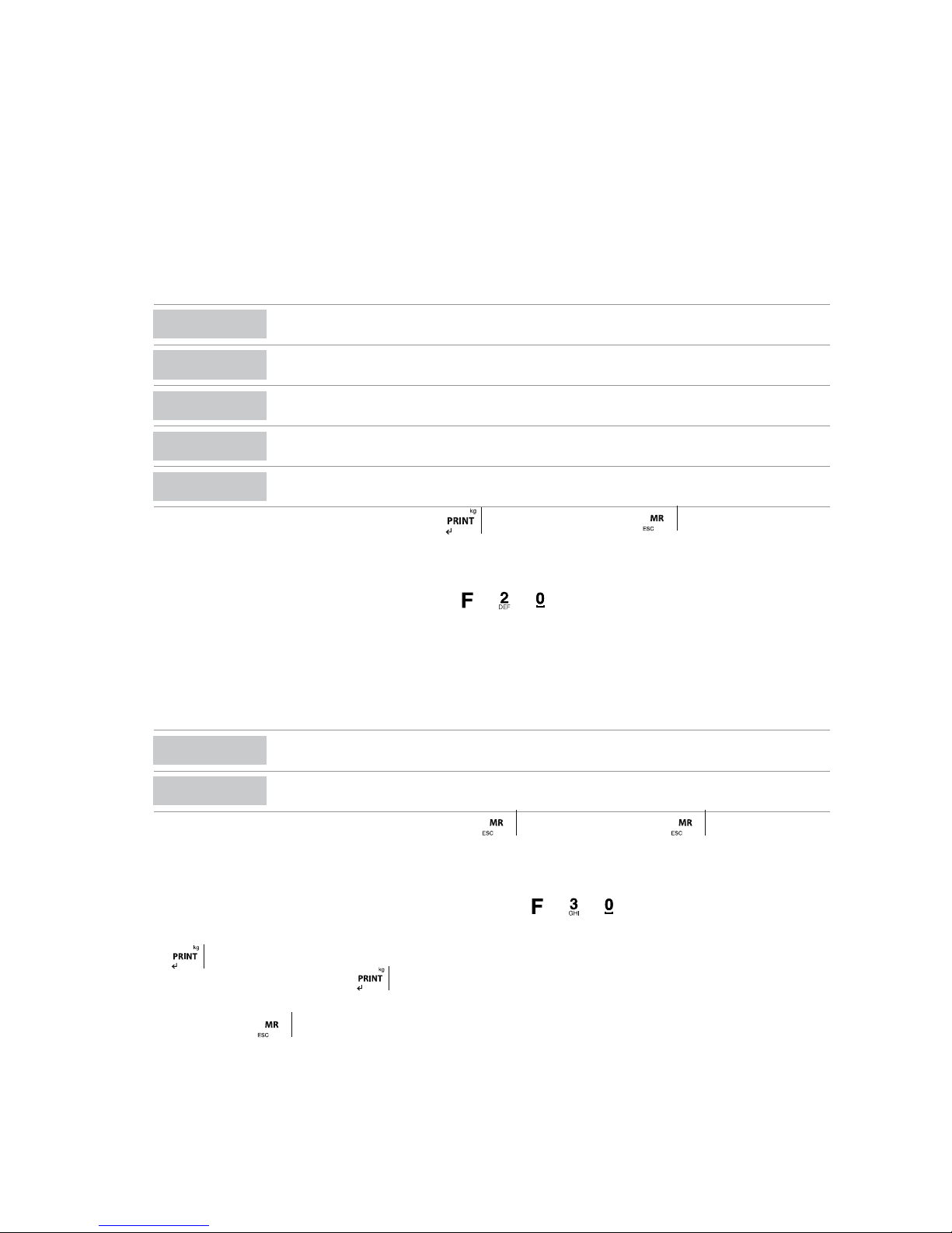
CHANGE THE NAME OF THE ITEM1 AND THE ITEM 2
Enter the technical no metrological menu, inside the menu CONFIG, select the option CODES.
Choose the items that you need to change the name from FILE1, FILE2.
Write the new name of the item in the numerical keyboard.
EXAMPLE
In FILE1 we write “lorry” and in FILE2 we write “product”, we press the ENTER key during each operation to confirm.
EDIT THE DATA OF THE ITEM OF THE TYPE OF WEIGHING (ITEM1)
From normal weighing mode press F + 7 + 0 (one after the other). Write the number of item 1 we want to edit
Now we introduce the desired data:
DISPLAY
DESCRIPCIÓN
CODE
numerical code of the item
DESCRI
description of the item with a maximum of 24 alphanumerical characters
TARE
value of the tare item
TYPE
to select the type of item WEIGHT, CHECKW or PMU, in the case of Checkweigh and PMU the user must
set its parameters
EANCODE
code EAN of the product
Once each one of the parameters are confirmed with the key
, the user must press the key , the screen will display briefly the
message SAVED and next it will return to the weighing mode. .
EDIT DATA OF THE DESCRIPTIVE ITEM (ITEM2)
Once the user is in the normal weighing mode, press the keys
+ + ( one after the other).
The screen is going to display the message PRO (the first three digits of the “product”), followed by 000.
Write now the number of the item2 that the user wants to edit, for example PR000 1 and press the key ENTER, the screen is going to display
the menu described beFore.
Introduce now the desired data:
DISPLAY DESCRIPTION
CODE
numerical code of the item
DESCRI
description of the item with a maximum of 24 alphanumerical characters.
Once each one of the parameters have been confirmed with the key
the user must press the key , the screen will briefly display
the message SAVED and next I will return to its weighing mode.
EDIT TARA DATA
Once the user is in the normal weighing mode of the device, press the keys + + ( one after the other).
The screen is going to show the message TARE00. Write the number of tare that the user wants to edit, for exampleTARE01 , and then press
the key
the screen is going to display the messageT00.000,, so that the user can introduce the value of tare.
Once it is set, the user must press the key to confirm the operation, the screen will briefly display the message SAVED and it is also
going to show again the message TARE01 so that the user can choose another tare to edit. Once the user has edited all the tares needed, the
user must press the key during 3 seconds so that the device goes back to its normal weighing mode.
Page 21
21
ENUSER MANUAL GI400 / GI410
CONNECT WEIGHING TO ITEMS AND TARE
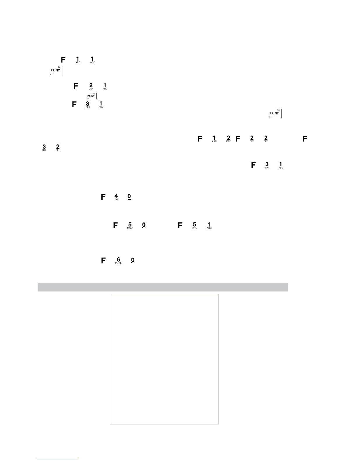
Each weighing can be connected to one or more items and/or a stored tare, to do so the user first needs to activate them. To do it first introduce
the activation code of each one of them.
EXAMPLE. Weighing linked to item1, item2 and to a tare.
Choose + + , the indicator is going to ask for the number of item1, we choose the desired one, CAM001 and then press the
key . If that key has a tare connected to it, it is going to be displayed on the screen.
Press the keys + + , the indicator is going to ask for the number of item2, the user must choose the desired number, PRO001
and then press the key .
Press the keys + + , the indicator is going to ask for the number of tare, the user must choose the desired number T01, and next
the indicator is going to ask if it is needed to activate it, if we press the option YES, then we must also press the key .
Now the user can proceed to do the weighing with an activated mode of accumulation, all the weighing are going to be stored with the associated data until the user selects other data or deactivates by pressing the keys + + ,
+
+ respectively or +
+ when proceeding with a tare.
NOTA: If the item1 has a pre tare with a value different to 0 and we also activate a tare by pressing the keys + + , the last one to
activate is the one which becomes effective.
SEE THE STORED INFORMATION
Via the combination of the keys + + , the user can view the information of a stored weighing. To view it the user must only introduce
the number of the weighing we are interested in viewing the data.
CUMULATED TOTAL OF THE ITEM ON THE SCREEN
By using the combination of the keys + + ( for item1) or + + ( for item2), the user can view the information of the
cumulated total associated to each item. To view it the user must only introduce the number of the item s/he is interested in viewing the data
cumulated total.
PULL OUT THE TOTAL LIST
Via the combination of the keys + + the user can pull out a total of the weighing no matter if they have been deleted or not from
the memory.
TOTAL LIST
Weighing info
From: 25/11/15
To: 11/04/16
---------------------------------
Gross total: 4.045 kg
Tare total: 0.800 kg
Net total: 3.245 kg
Pieces total: 000000
Weighing total: 000067
---------------------------------
Page 22

ENUSER MANUAL GI400 / GI410
22
LIST FILTERED PER ITEM1, ITEM2 AND DATE
By using the combination of the keys
+ + , the user can select the number of item2 (PRO001 ),, then the number of the item1
(CAM001) and decided not to filter by date ( date NO)
FILTERED LIST
Report: Weighing
11/04/2016
---------------------------------
From: 00/00/00
To: 11/04/16
Product: 001
Lorry: 001
---------------------------------
Lorry number: 001
Lorry code: 000122
Lorry: Mpdj
Product number: 001
Product code: 005508
Product:
Gross weight: 1.000 kg
Tare: 0.200 kg
Net weight: 0.800 kg
Number of pieces: 000000
Lorry Number: 001
Lorry code: 000122
Lorry: Mpdj
Product number: 001
Product code: 005508
Product:
Gross weight: 1.000 kg
Tare: 0.200 kg
Net weight: 0.800 kg
Number of pieces: 000000
Lorry Number: 001
Lorry code: 000122
Lorry: Mpdj
Product number: 001
Product code: 005508
Product:
---------------------------------
Gross Total: 3.000 kg
Tare Total: 0.200 kg
Net Total: 2.400 kg
Pieces Total: 000000
Weight Total: 000003
---------------------------------
Page 23
23
ENUSER MANUAL GI400 / GI410
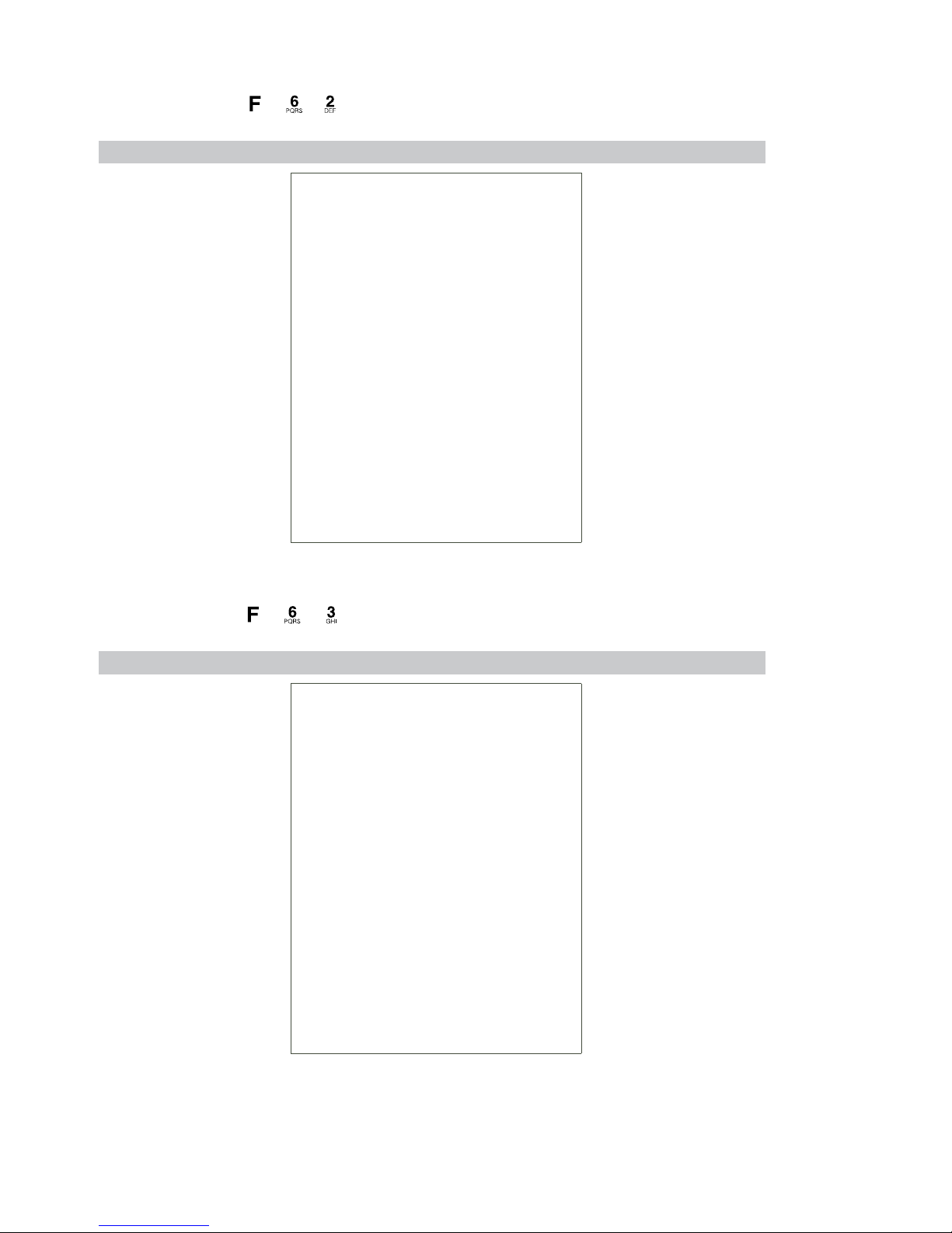
FILTERED LIST PER ITEM2
In this case we use the keys + + and we select the number of item2(PR0001)
FILTERED LIST PER ITEM2
Report: Weighing
11/04/16
---------------------------------
Product number: 001
Product code: 005508
Product:
Gross Total: 3.000 kg
Tare Total: 0.200 kg
Net Total: 2.400 kg
Pieces Total: 000000
Weight Total: 000003
---------------------------------
FILTERED LIST PER ITEM1
To do so we press the keys + + and select the number of item1 (CAM001)
FILTERED LIST PER ITEM1
Report: Lorry
11/04/16
---------------------------------
Num camion: 001
Codigo Lorry: 000122
Lorry: Mpdj
Gross Total: 4.200 kg
Tare Total: 0.800 kg
Net Total: 3.400 kg
Pieces total: 000000
Weight total: 000004
---------------------------------
Page 24
ENUSER MANUAL GI400 / GI410
24
DELETING ÍTEM1
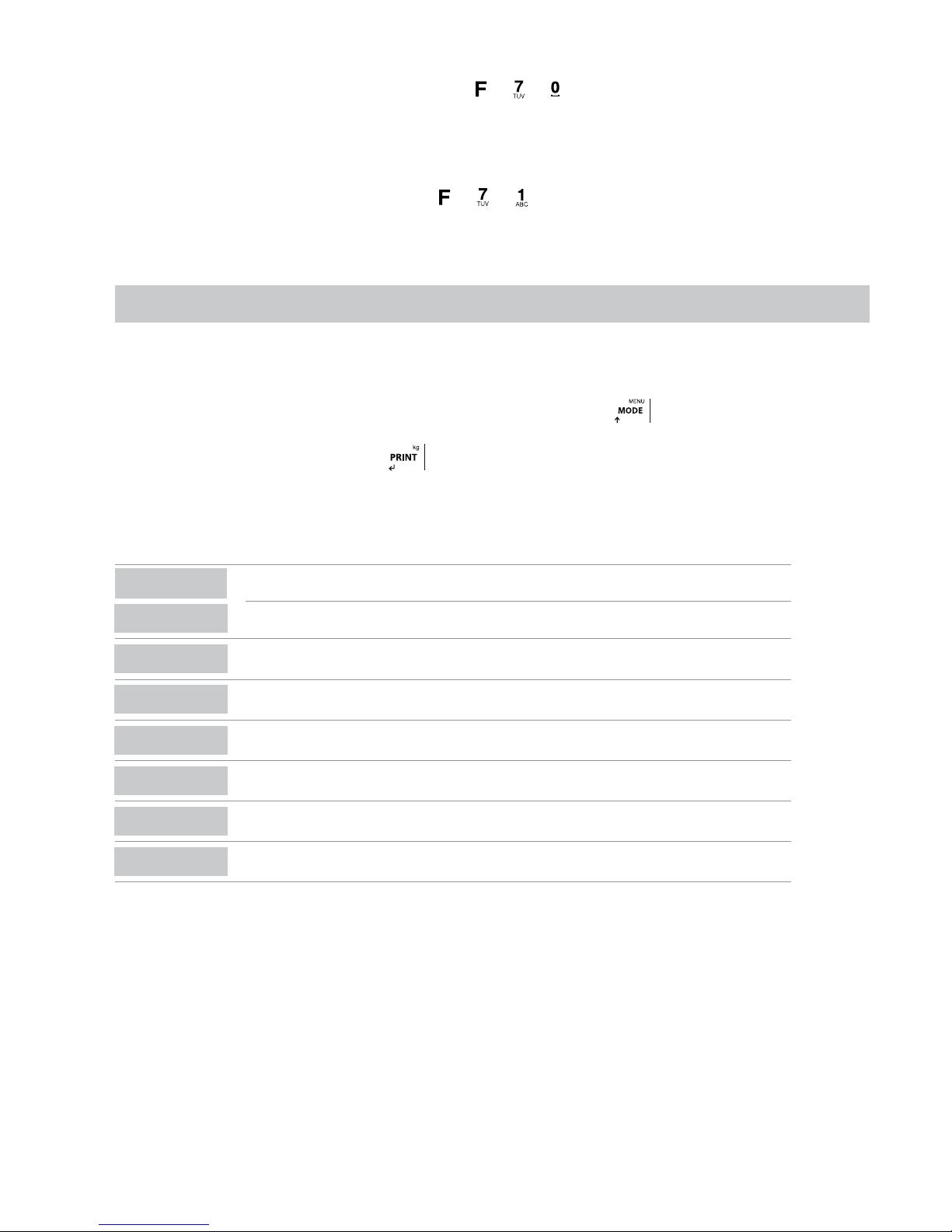
This operation can be done by using the combination of the keys
+ + , we can delete the information related to an item. To do so
the user must select the desired item CAM001 and then choose between ALLCAM (it deletes all the information which refers to CAM001
including the item CAM001 ) and TOTCAM( it deletes the cumulated total referring to CAM001 , without deleting the item CAM001 )
DELETING ITEM2
This operation is done using the combination of the keys + + , we can delete the information related to an item. The user must
select the desired item PRO001 and then choose between ALLPRO ( it deletes all the information which refers to PRO001 including the item
PRO001 ) and TOTPRO ( it deletes the total stored referring to PRO001, without deleting the item PRO001 )
6. NO METROLOGICAL TECHNICAL MENU
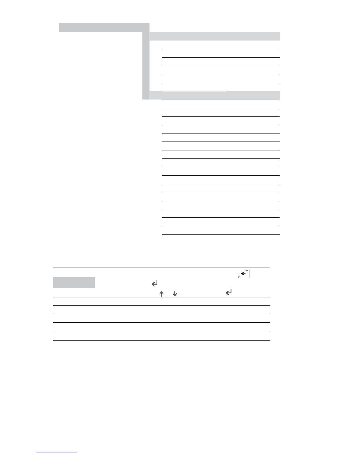
In this page the user can find the description of the options of the LIMITED PROGRAMATION. Functions to personalize ONLY the configuration
of the NO METROLOGICAL PART (printers, peripherals, analog exits and relays):
• The procedure of the limited programming is done by pressing for a long time the key
• A pin code must be inserted (4 digit numbers)
The pin of factory is 0000:
Pi0000,
press
for confirm.
Note: The functions availables are the following:
DISPLAY
DESCRIPTION
(metrological)
CAL-PA
CAL 0
(metrological)
CAL
(metrological)
9rAuit
(metrological)
ParaMe
Config
Abt VM
dEFAUL
(metrological)
Page 25
25
ENUSER MANUAL GI400 / GI410
6 Technical menu NO metrologic
Parameters (Parame)
COM1, COM2, RS485, COM4
Frame
Baud
Protoc
Addres
Delive
Configuration (Config)
Filter
Date
Time
mV
I.COUNT
Language
CA.PASS
AUTARB
Stand.by (solo para LED)
BLIGHT (only for LCD)
Print
Codes
Power
Repeat
Tcheck (visible only in open calibration)
Decimal (visible only in open calibration)
6.1.MENU PArAME : COM1, COM2, RS485 Y COM4
Once the Pin is introduced in the mode of limited programming, the display is going to show the following message:
PArAME
In the mode of opened programming, it will show CAL--PA, press key till it
show PARAME. Press for access. With this function you can set NON METROLOGICAL parameters. Use and for select the option and for access.
COM 1 Setting up port 1 Rs 232 to PC, Printer, etc….
COM 2 Setting up port 2 Rs 232 to PC, Printer, ethernet, etc….
RS485 Setting up port 2 on Rs 485 mode. Option only available with RS 485 board.
COM 4 Ethernet port configuration. option is available only via Ethernet board (optional)
FRAME
The frame allows data communication format.
The possible choices are:
8n1, 8n2, 8e1, 8o1, 9n1, 9n2, 9e1, 9o1
BAUD RATE bAUd
It allows the definition of the speed of communication using the cannel of series rs232 com1, com2 and Rs485
The possible choices are:
300, 600, 1200, 2400, 4800, 9600, 19200, 38400, 57600, 115200 baud.
Page 26

ENUSER MANUAL GI400 / GI410
26
PROTOCOLO ProtoC
Currently the terminal includes different protocols of communication that can be used through the port of RS-232:
nInGUn
No protocol Enabled
IMP
Printer Protocols
GIPEs
Giropes Protocols
SPI2
Protocol – SIPI II
tol dS
Protocol – Toledo DS
ErIC
Protocol - ERIC
EPSA
Protocol EPELSA
EPEL A
Protocol EPEL A
EPEL 80
Protocol EPEL80
M-t
Protocol of METLER
MobbA3
Protocol Mobba3
F501
Protocol of F501
SAIE
Protocol SAIE
MultiP
Protocol MULTIPUNTO 2000
SEUr
Protocol SEUR
tISA
Protocol TISA
Ud-0
Protocol VD0
SSCAr
Protocol SENSOCAR
CSCOMP
Protocol CAS NOVITUS
Sb-400
Protocol SB-400
SMART
Protocol Smart
TXL
Protocol Teacsul
bILANC
Protocol Bilancai
br80
Protocol BR80
br80 I
Protocol BR80i
Note: Protocols are explained in the technical Protocols manual
GrAVIT
Protocol – GRAVIT
ALIbI
Fiscal Memory Protocol
GICoNF
Communication protocol with GISCALE
rAFEL
Protocol - RAFELS
bIZErb
Protocol – BIZERBA
SPI O
Protocol – Sipi O.
APLUS
Protocol – Aplus
CAMP
Protocol – Campesa
Page 27
27
ENUSER MANUAL GI400 / GI410
ADDRESS AddrES
It allows to adjust the direction of the terminal when the RS485 is used in the protocols that contemplate it (SSCAR and MULTIP).
SEND (Mode of transmission) dELiuE
It allows the configuration of the terminal to send the information to the PC through one of the following modes:
Pc request PcrE: the terminal sends the chain of information, depending on the protocol, when the order from the PC has been
received.
Continuos Contin : the terminal sends the chain of information, depending on the protocol, in a continuous way.
Interval intERv : the terminal sends the chain of information, depending on the protocol, when a variation of the weight is obtained.
Stable 0 Stb 0 : the terminal sends the chain of information, depending on the protocol each time takes stability and the value is
different to 0. It needs to pass trought 0 each time.
Repeti REPETI : On this mode the indicator work as a repeater from another GI400 in mode SIPI II continues or interval. Valid for
RS485, for RS232 (limit distance: 16m) or ethernet. In RS232 case, use the CM2 in both computers
ESTODE ESTOdO : (Zero to discharge)
Stable stablE : The terminal sends the data chain, depending on the protocol each time it acquires a stable weight.
Manual MAnuAL: The terminal sends the data chain, depending on the protocol, to the pressure of the key
OPTIONAL RS485
Only works with RS485 board.
Protocols available on RS485 mode with ID are:
MULTIPOINT 2000 AND SENSOCAR WITH INDICATOR CAN BE SET AS A REPEATER.
On indicator with RS485 board board you need to set
PARAME è RS485 è Protocolo SIPI II è Trigger contin.
On indicator with RS485 board wich works as a repeater, you need to set
PARAME è RS485 è Protocolo SIPI II è Trigger romte.
6.2 ETHERNET MENU ( IT ONLY WORKS WITH AN OPTIONAL ETHERNET BOARD)
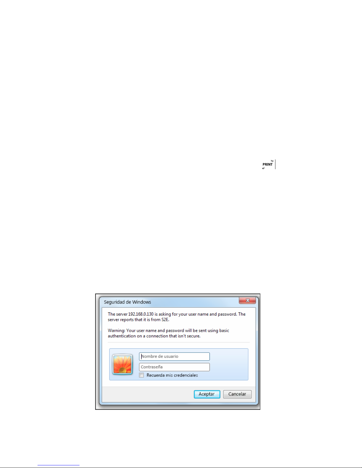
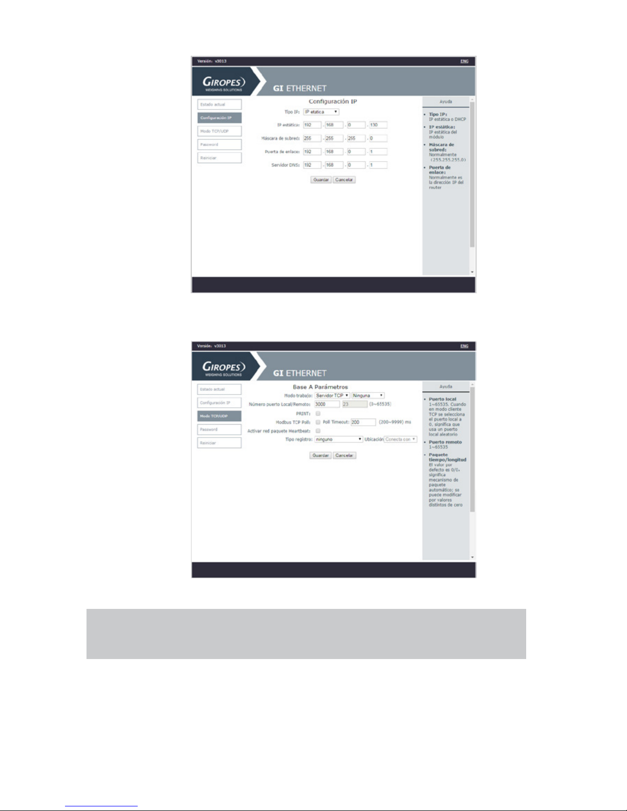
Connect the equipment to the PC using a switch. Enter the IP of the device in the browser 192.168.0.130 (by default)
Enter the username and password. (Admin and 1234 by default)
In the “Local IP Config” tab you can change the IP
Page 28
ENUSER MANUAL GI400 / GI410
28
In the “TCP / UDP mode” tab you can change the port.
You can change the username and / or password in the Misc Config
If you forget them, you have to open the device and press the RST pads for 5s to reload the factory
settings.
Page 29

29
ENUSER MANUAL GI400 / GI410
6.3 MENU CONFIGURATION
Once the PIN has been introduced, the user is in the mode of restricted programming, move up to
ConFIG
. By using this function the user can
program the following NO METROLOGICAL parameters:
FiLtEr
filters
FEchA
date
dAtE
hour
Mv
mV of the cell
ICoUnt
Internal accounts
LAnG
Languange
CH.PASS
Password change
AUtArb
Auto-Lock Tara
StAnbY
autostanby (only for LED version)
blIGht
Backlight è (only for LCD version)
PrInt
Print settings
CodES
Name of the item1, item2 and tcode
PoWEr
Selecting the internal battery type
rEPEAt
Retransmission of plot in repeater mode
tCHECt
(Visible only in open calibration)
dECIMA
(Visible only in open calibration)
FILTER: Media weighting filter. Being 1 the most robust 6 the most sensitive.
DATE: Select the date in the format DD.MM.AA. Being DD the day, MM the month and AA the year.
TIME: Select the time using the format hh.mm.ss. Being hh the time in format 24h, mm the minutes and ss the seconds.
AUTOSTANBY: Autostandby time selection. If toFF is set to 00, the Autostandby is disabled. The value entered is the time without weight
variation or keystroke that takes to enter standby. It only works when the power comes from the optional battery.
MILIVOLTS: mV: It shows the milivolts of the load cell.
I.COUNT : Displays the A/D converter data, press to exit.
LANGUAGE: Using this menu the user can choose the language in which the tickets are going to be printed and which appears on the display.
The languages that are available are: Spanish, French, English, French and Italian.
PASSWORD CHANGE: It changes the entrance password to the technical menu, the user must introduce first the current password and then
the new one. The password by default is 0000.
AUTARB: Using this menu the user can choose if s/he wants to block the tare automatically.
BACKBLIGHT: allows to select backlight working mode whithin Auto, ON, OFF (only for LCD devices).
PRINT: Select the type of printer, the auto cutter, the number of line advances at the end of the ticket and the number of copies of the ticket.
CODES: It allows to edit the name of the item1, item2 and tcode.
POWER: Selection of type of power supply, network, optional battery (3, 7V), optional lithium battery (7.4), this parameter activates the charge
indication according to the type of battery.
REPEAT: In this menu you can choose whether to re-send or not, the received frame, in the case of using the viewer a repeater of another.
TCHECK: (Under development)
DECIMA: Allows us to select the decimal separator as comma or point.
Page 30
ENUSER MANUAL GI400 / GI410
30
6.4 ABT VM
Shows the different versions of the program.
6.5 DEFAUL
Restore factory defaults.
7. PRINTER
The available printers are the following ones:
IMP05
IMP27
IMP28
The working of the printer is described below:
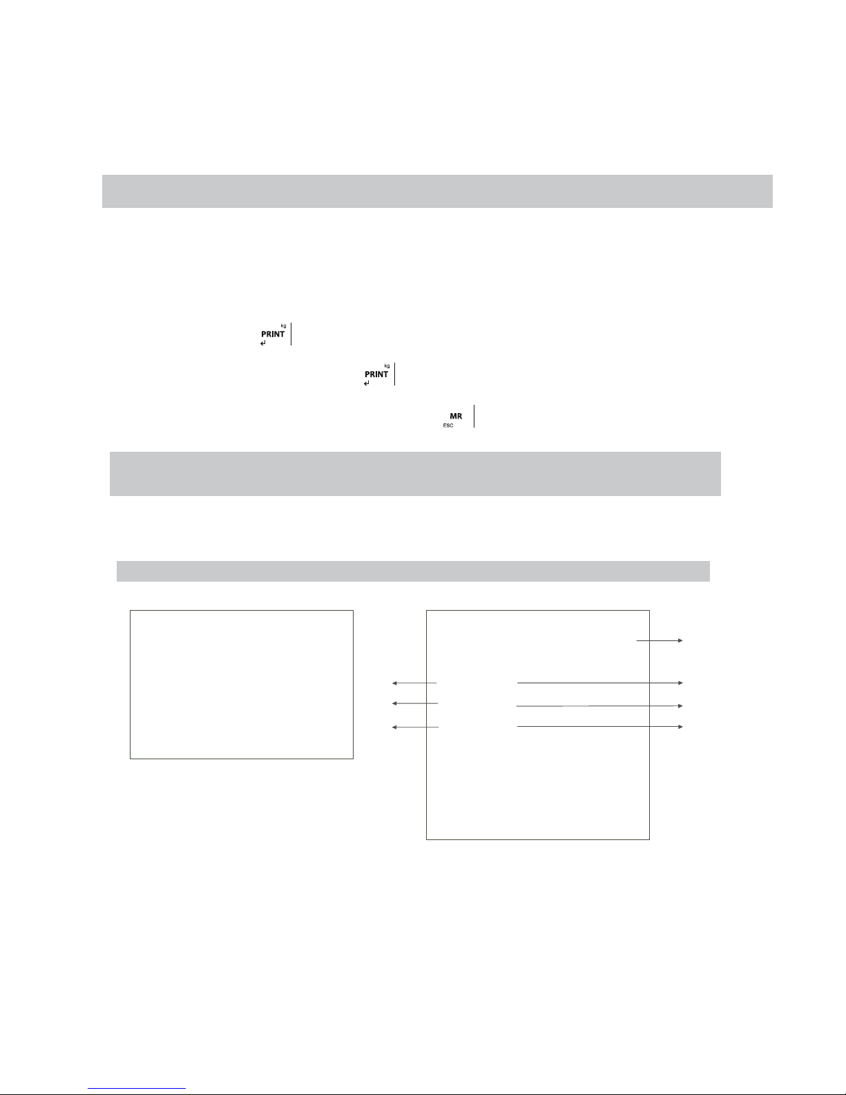
When the user presses the key
the weight is printed, with its number of weighing and its corresponding tare if the mode of transmission is manual (5.1.15).
The user can do successive weights pressing the key
. This process can be done if the system goes first to zero or if a tare is done or if
an additional weight is situated on the platform.
Once the user has done all the needed weights, when pressing the key
the user will obtain the definitive ticket with the number of
weights and the total weight in case that the device has the accumulation option in active mode
If the accumulation mode is automatic, you must choose shipment or Stable 0 or ESTOdE. Or Stable On the other
hand, if the accumulation mode is manual you will have to choose manual shipment.
The printed ticket has 40 characters wide.
7.1 TICKET FORMATS GI400:
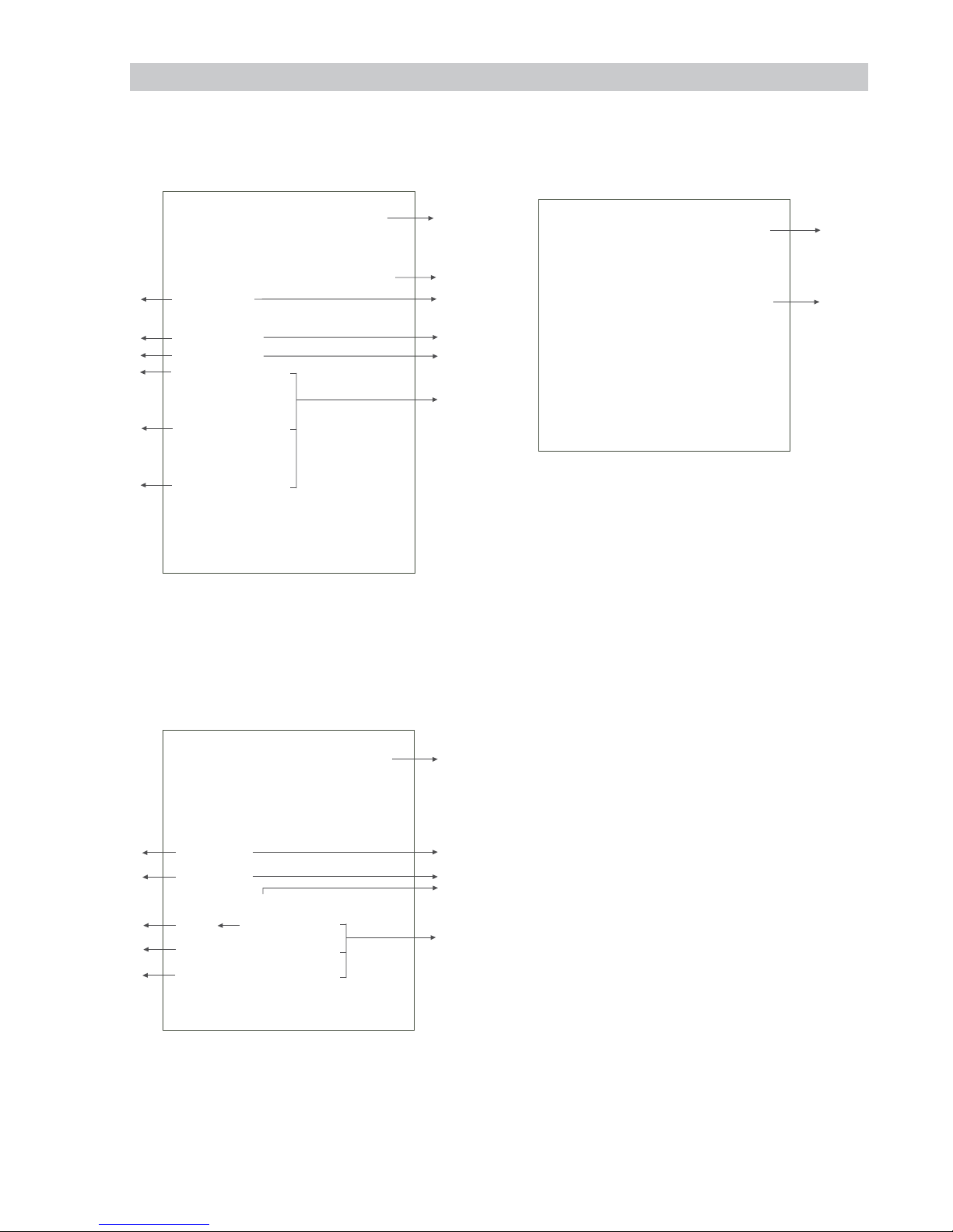
FORMATS FOR WEIGHT
F. Imp.1 F. Imp.1 (Numeric keypad only)
Date: 28/02/2018 Time: 11:08:06
Gross: 654 kg
Tare: 0 kg
Net 654 kg
_____________________________________
Weighing Number: #1
Date: 28/02/2018 Time: 11:15:12
T code: 123
Truck: Cuba
Grain: Maiz
Gross: 654 kg
Tare: 10 kg
Net 644 kg
_____________________________________
1
2
3
4
6
5
7
Page 31
31
ENUSER MANUAL GI400 / GI410
FORMATS COUNTING
F. Imp. 2 F. Imp. 2 (numeric keypad only)
Date: 28/02/2018 Time: 11:32:35
PMU: 20000.001953 g
Gross: 654 kg
Tare: 0 kg
Net 654 kg
Units 33 u
_____________________________________
Weighing Number: #5
Date: 28/02/2018 Time: 11:15:12
T code: 123
Truck: Volquete
Grain: Piedras
PMU: 20000.001953 g
Gross: 652 kg
Tare: 0 kg
Net: 652 kg
Units: 33 u
_____________________________________
FORMATS CHECKWEIGHER
F. Imp 3 F. Imp 3 (With Item, nº weighing and T Code)
Date: 28/02/2018 Time: 11:37:08
Target Weight: 500 kg
Actual weight: 652 kg
Deviation: 152 kg
_____________________________________
Weighing Number: #1
Date: 28/02/2018 Time: 11:38:31
Tcode: 123
Truck: Remolque
Grain: Cebada
Target weight: 100 kg
Actual weight: 644 kg
Deviation 544 kg
_____________________________________
TOTALITZATION (FORMATS 1-2-3)
F. Imp 1-2-3 F. Imp 1-2-3 (+ wheighing nº)
=====================================
TOTAL
=====================================
Date: 28/02/2018 Time: 11:37:08
*************************************
Weighing Number: 00002
=====================================
Tot Gross: 2614 kg
_____________________________________
Tot Tare: 10 kg
_____________________________________
Tot Net: 2604 kg
=====================================
=====================================
TOTAL
=====================================
Date: 28/02/2018 Time: 11:42:10
*************************************
Weights: #00001 - 00001
Number of weights: 00001
=====================================
Tot Gross: 654 kg
_____________________________________
Tot Tare: 10 kg
_____________________________________
Tot Net: 644 kg
=====================================
1
2
3
4
6
5
7
1
2
3
4
6
5
7
1
Page 32
ENUSER MANUAL GI400 / GI410
32
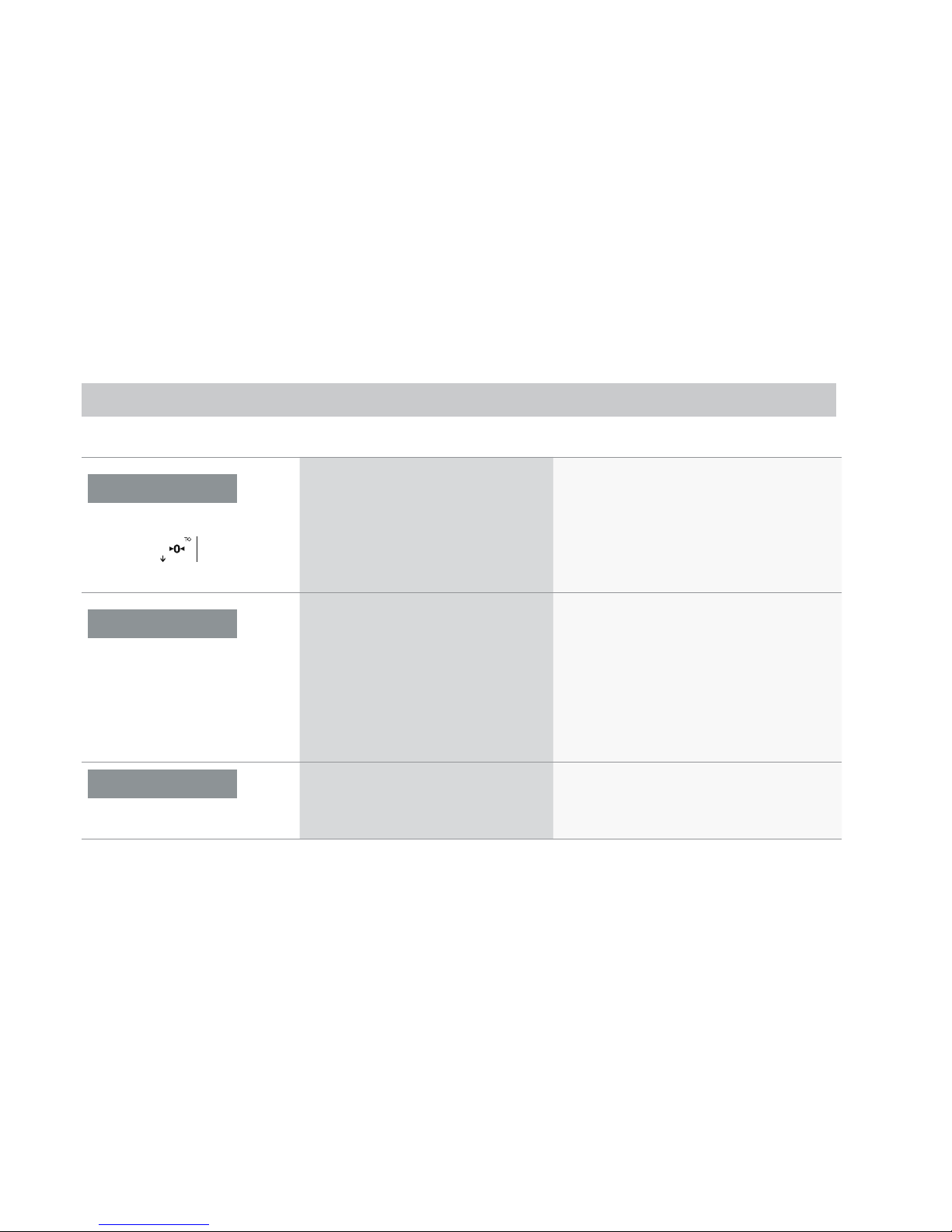
FORMATS FOR ACCUMULATION (MANUAL OR AUTOMATIC) WITH TOTALITZATION
F. Imp 4 (Linea a linea) F. Imp 5
3 header lines of 40 characters editable with the software
“configuration tool”
3 header lines of 40 characters editable with the software
“configuration tool”
Date: 28/02/2018 Time:11:37:00 Prg:001
Nr. Ticket: 000001 Code: 000011
G 6523 kg
T 0 kg
N 652 kg
___________________________________
F. Imp 6 (Line-to-line)
3 header lines of 40 editable characters with
the software “Configuration Tool”
Time: 28/02/2018 Date: 11:37:00
T code: 1234
Grain: Maiz
N.Weight Camion N.Art. Net kg
1 Cuba 00011 74 kg
2 Cuba 00011 136 kg
3 Cuba 00011 236 kg
TOTAL NET: 446 Kg
6
8
8
8
2
3
5
7
4
_________________________________
_________________________________
_________________________________
9
_________________________________
_________________________________
_________________________________
9
10
2
Nr. Ticket
28/02/2018 11:38:31
000013
T code : 1234
T
ara
Camion : Cuba
Grano : Maiz
1 000011 10 kg 74 kg
Camion: Cuba
Grano: Maiz
2 000011 10 kg 136 kg
Camion: Cuba
Grano: Maiz
3 000011 10 kg 236 kg
00003 446 kg
476 kg
__________________________________
1
3
4
5
6
8
8
8
7
_________________________________
_________________________________
_________________________________
9
Date:
N. Weight
Tot.Gross Kg Tot.Net Kg Tot.Weights
Net
Time
10
10
Page 33
33
ENUSER MANUAL GI400 / GI410
LEGEND
1- The initial value of the editable counter from which each new ticket is added (in the 1-3 format, the weighing number = ticket number. If the
ticket number is at zero, it will not appear).
2- Fixed editable number (if we have the value to 0, will not appear in the ticket)
3- Fixed editable field (if we have the value to 0, will not appear in the ticket.
4- Name Item 1 (only with item 1 on)
5- Value active record of item 1 (only with item 1 on)
6- Name Item 2 (only with item 2 on).
7- Value active record of item 2. (Only with Item 2 on).
8- Weighing number.
9- Header lines (only appear if we have previously edited).
10- Code Element 1
8. ERROR MESSAGES
DISPLAY POSSIBLE CAUSES SOLUTION
- O -
Function of initial zero setting or
through a key
in process (blinking message).
1. On the scale is weight value superior to the
accepted limit of the function
1. Unload the scale .
2. The weight on the scale is not steady.
2. Wait until the weight is steady.
If the anomaly persists you must ask for help to your
supplier service centre.
Over L
OVER LOAD
The analog sign of the load cell is out of
the working range of the A/D chip. This
error finishes when the sign reenters the
expected range.
1. Connector of the load cell not connected..
2. Broken cable.
3. Broken load cell (due to overload)
4. Weight on the top scale at its maximum
weight.
1. Control that the connector is correctly connected.
2. Control carefully the cable of connection to the load
cell and replace it if it defective.
3. Control the sign of the cell when unloading. If it is
very high you must also replace it.
If the anomaly persists you must ask for help to your
supplier service centre
.
_ _ _ _ _ _ _
ERROR RD/WR EEPROM
1. Error after an operation of Reading or writing
of the EEprom device
If the anomaly persists you must ask for help to your
supplier service centre.
Page 34
ENUSER MANUAL GI400 / GI410
34
9. CONNECTIONS
9.1 CONNECTION SCHEME IP54
9.1.1 LOAD CELL
The device is completely supplied for the connection of the transducer (load cell). The kit includes:
• 1 male connector to be welded (9 tracks)
• 1 coverage/blocking cable protected
The cable that comes from the transducer or transducers is connected by welding it to the device. The user must be very careful with
its quality and the isolation between the conductors and the use of a good alloy of tin. A bad quality product or a product that is not
appropriated could damage or alter the correct working of the device..
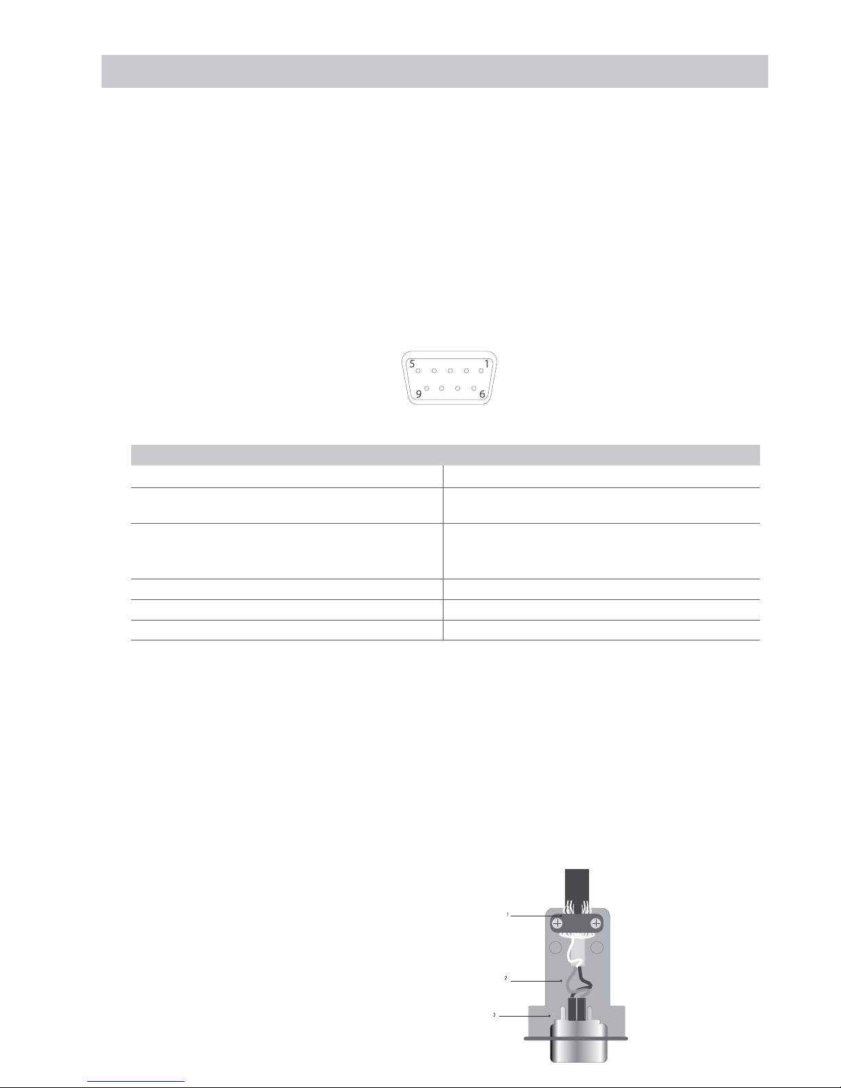
In the figure 7 it is indicated the topography of the connector; the pins have the following functions:
Fig. 8 - Delta connector 9 tracks for the LOAD CELL(S) ENTRANCE
FUNCTION PIN IN C.D.C.
N° PIN NAME FUNCTION N°PIN NAME FUNCTION
1 -EXC (- EXCITATION) 4 +SENSE (+ TERMINAL OF CORREC-
TION)
2 -SENSE (- TERMINAL OF
CORRECTION)
5 +EXC
(+ EXCITATION)
3 GND_A (ANALOG MASS) 6
NOT CONNECTED
7 -OUT (- TRANSDUCER SIGN) 9 NOT CONNECTED
8 +OUT (+ TRANSDUCER SIGN)
If the transducer includes a connection cable with 4 wires plus protection, and not with 6 wires plus protection, the excitation (+) of the device
must be connected with SENSE (+) and the excitation (-) with SENSE (-) joining the pin 1 with the pin 2 and the pin 4 with the pin 5.
To reduce the electrical and radio interferences to the minimum , all the connection cables between the device and the transducer must be of a
protected type, and all the system must be connected to an optimal earth wire.
The supplying company of the device can supply a type of connection cable that was made on purpose for such conditions. This cable includes
a double protection to be welded to the terminals of the shield or on earth.
The following figure shows the different parts involved in the connection of the shields of protection of the cable.
Impedancia mínima 25 Ω
Impedancia máxima 1100 Ω
1 External protection of the cable. It must be pressed in the
metal box for cables with terminal moustaches which must
be tightened between the two lids of the coverage
2 Ending of the internal protection of the cable. It must be
closed in the metal box for cables of the NB. Protection: Do
not connect to the pin 3 of the connector
3 Coverage protected with conductive material
Page 35

35
ENUSER MANUAL GI400 / GI410
9.1.2 INTERFACE SERIE RS-232 COM1 Y COM 2
The instrument has serial outputs type RS232
Description of the connector pin-out male exit series RS232-com1
n° pin Description Direction
2 TX (RS232c - transmitter) Exit
3 RX (RS232c - receiver) E
5 GND (signal common)
9.1.3 ADDITIONAL BOARD RS-485 COM2 (DB9)
n° pin Description
1 EARTH
8 RTx-
9 RTx+
9.1.4 ADDITIONAL BOARD 4-20mA/ 0-10V ANALOGUE
n° pin Description
6 GND
7 V
OUT
8 I
OUT
-
9 I
OUT
+
9.1.5 ADDITIONAL BOARD4E/4S(relés) (DB25)
n° pin Description n° pin Description
1 RLY1_C 13 IN1-
14 RLY1_NO 25 IN1+
2 RLY2_C 12 IN2-
15 RLY2_NO 24 IN2+
3 RLY3_C 11 IN3-
16 RLY3_NO 23 IN3+
4 RLY4_C 10 IN4-
17 RLY4_NO 22 IN4+
5 +5V
DC
9 +5V
DC
Page 36
ENUSER MANUAL GI400 / GI410
36
9.2 CONNECTION SCHEME IP65 / IP68
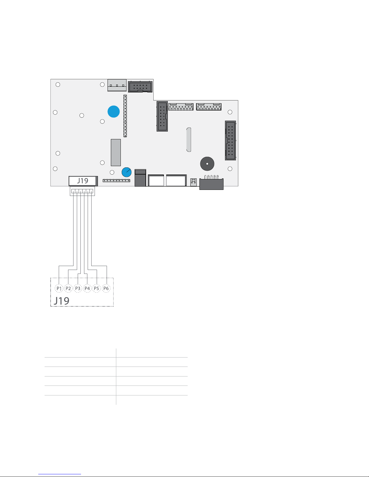
9.2.1 LOAD CELL
CELL CABLE
CONNECTOR J19
pin 1 IN+ (out célula)
pin 2 IN- (out célula)
pin 3 SENSE+
pin 4 SENSEpin 5 EXC+
pin 6 EXC-
Page 37
37
ENUSER MANUAL GI400 / GI410
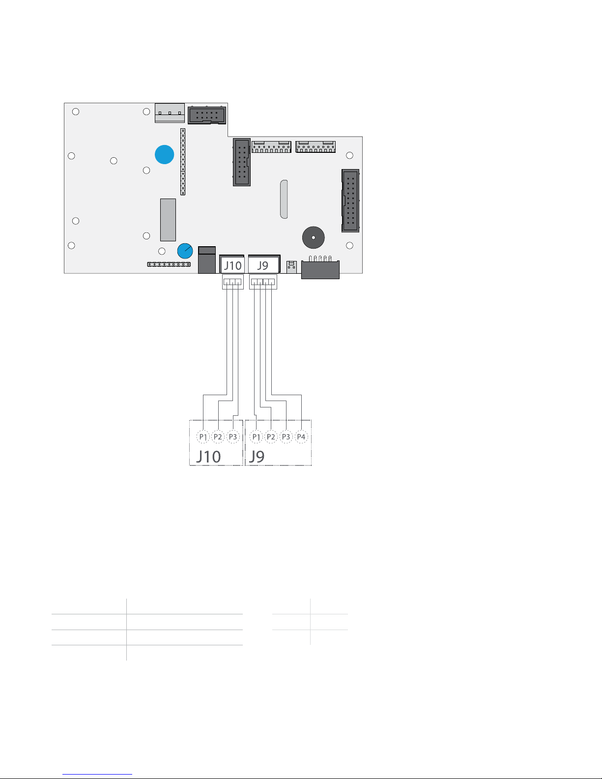
9.2.2 SERIAL INTERFACE RS232 COM 1 Y COM 2
COM 1
RS232
CONNECTOR J9
COM 2
RS232
CONNECTOR J10
pin 1 - pin 1 RX
pin 2 RX pin 2 TX
pin 3 TX pin 3 GND
pin 4 GND
Page 38
ENUSER MANUAL GI400 / GI410
38
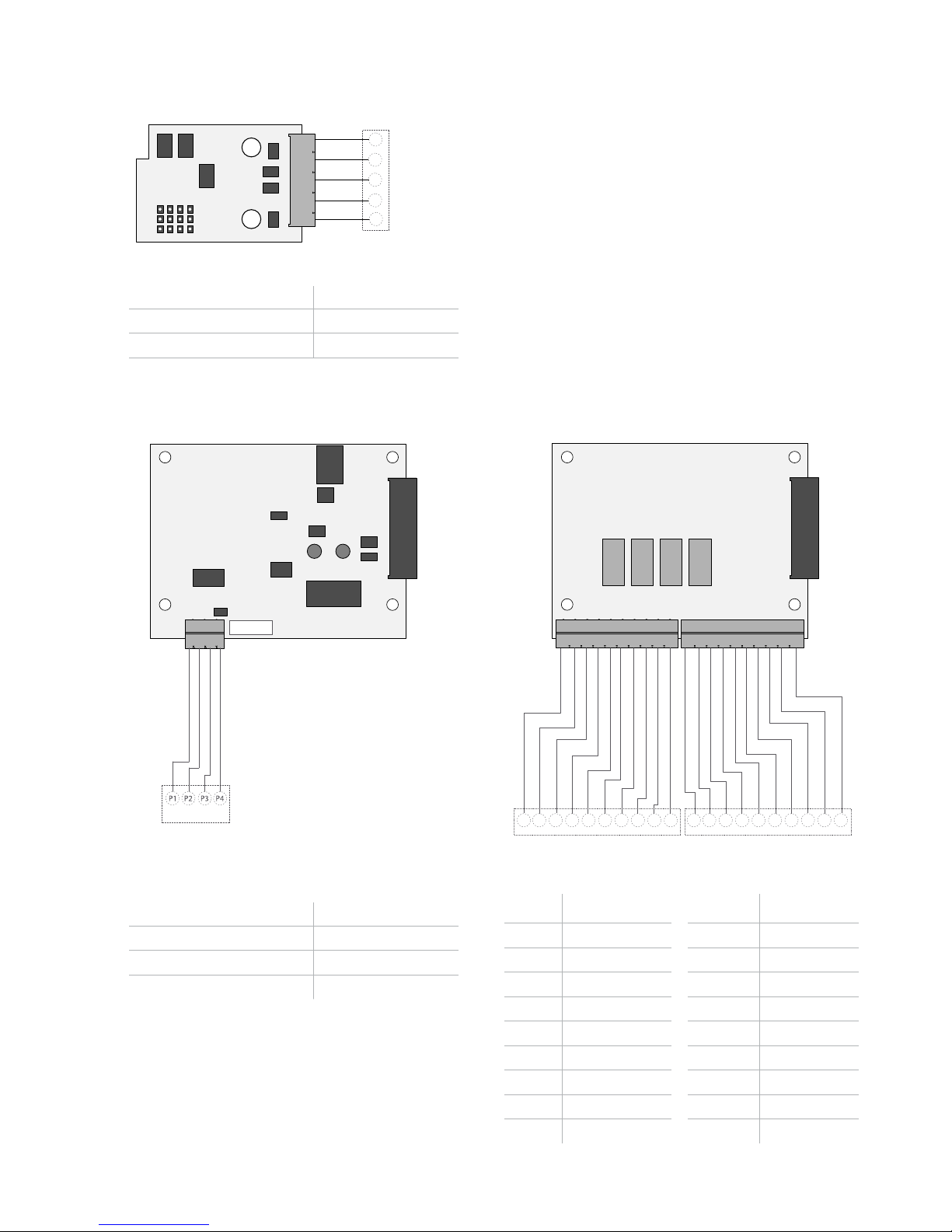
9.2.3 OPTIONAL SCHEME RS485
4-20mA
4-20mA
P1
P2 P3 P4
P5
J2
J2
pin 1 RTX +
pin 2 RTX pin 5 EARTH
9.2.4 OPTIONAL SCHEME 4-20MA/ 0-10V ANALOGIC (DB9) 9.2.5 OPTIONAL SCHEME 4I/4O (RELÉS)
4-20mA
J2
J2
CONNECTOR J2
pin 1 I
OUT
+
pin 2 I
OUT
-
pin 3 V
OUT
+
pin 4 V
OUT
- (GND)
RELES
COM
4-20mA
P1 P2 P3 P4 P5 P6 P7 P8 P9
P10
P1 P2 P3 P4 P5 P6 P7 P8 P9
P10
J2
pin 1 RLY1_C pin 1 IN1 pin 2 RLY1_NO pin 2 IN1 +
pin 3 RLY2_C pin 3 IN2 pin 4 RLY2_NO pin 4 IN2 +
pin 5 RLY3_C pin 5 IN3 pin 6 RLY3_NO pin 6 IN3 +
pin 7 RLY4_C pin 7 IN4 pin 8 RLY4_NO pin 8 IN34+
pin 9 + 5V
DC
pin 9 + 5V
DC
pin 10 GND pin 10 GND
Page 39
39
ENUSER MANUAL GI400 / GI410
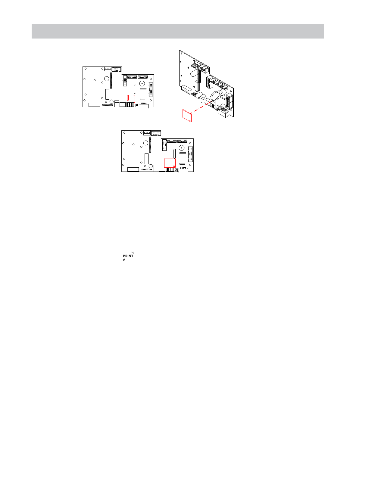
10. DSD MEMORY IP54 / IP65 / IP68
It is possible to increase the operation of the weight indicator with the additional plate that performs the function of FISCAL MEMORY; It
consisted in filing all the weight values transmitted to a computer for a subsequent processing or integration of the data transmitted by the COM
serial channel.
Each archived value is associated with an ID code. The stored value can be consulted in the display of the indicator using the ID. (As control with
respect to data printed by the PC).
The fiscal memory can store a maximum of 400 000 weighings, after which, it re-writes on the heavy number 0.
With the serial command “PID” or via the key , the scale number, the gross weight, the tare weight and an ID that unequivocally identifies the
weighing is sent, only in case the platform is stable and the gross weight is not negative.
The ID have the following format:
<Unique code number>, <Number of weight>
Unique code number: 5 digit number ranging from 0 to 99.999, indicative number of complete single code of fiscal memory.
The fiscal memory can store a maximum of 400 000 weights, after which the weighing number starts again by 00000 and the unique code number
is incremented one at a time.
The weighing relative to an ID can be verified only if:
Has a unique code number equal to the current one in the fiscal memory and a weighing number less than or equal to the last value received with
the “PID2” command.
Page 40
ENUSER MANUAL GI400 / GI410
40
11. REMOVAL OF ELECTRONIC EQUIPMENT
For the European Union customers:
All the products that have arrived to its ending in their life
cycle must be restored to their builder so that they can
be recycled. For further information about the restoring
modalities, please contact your supplier.
12. OPTIONAL BATTERY
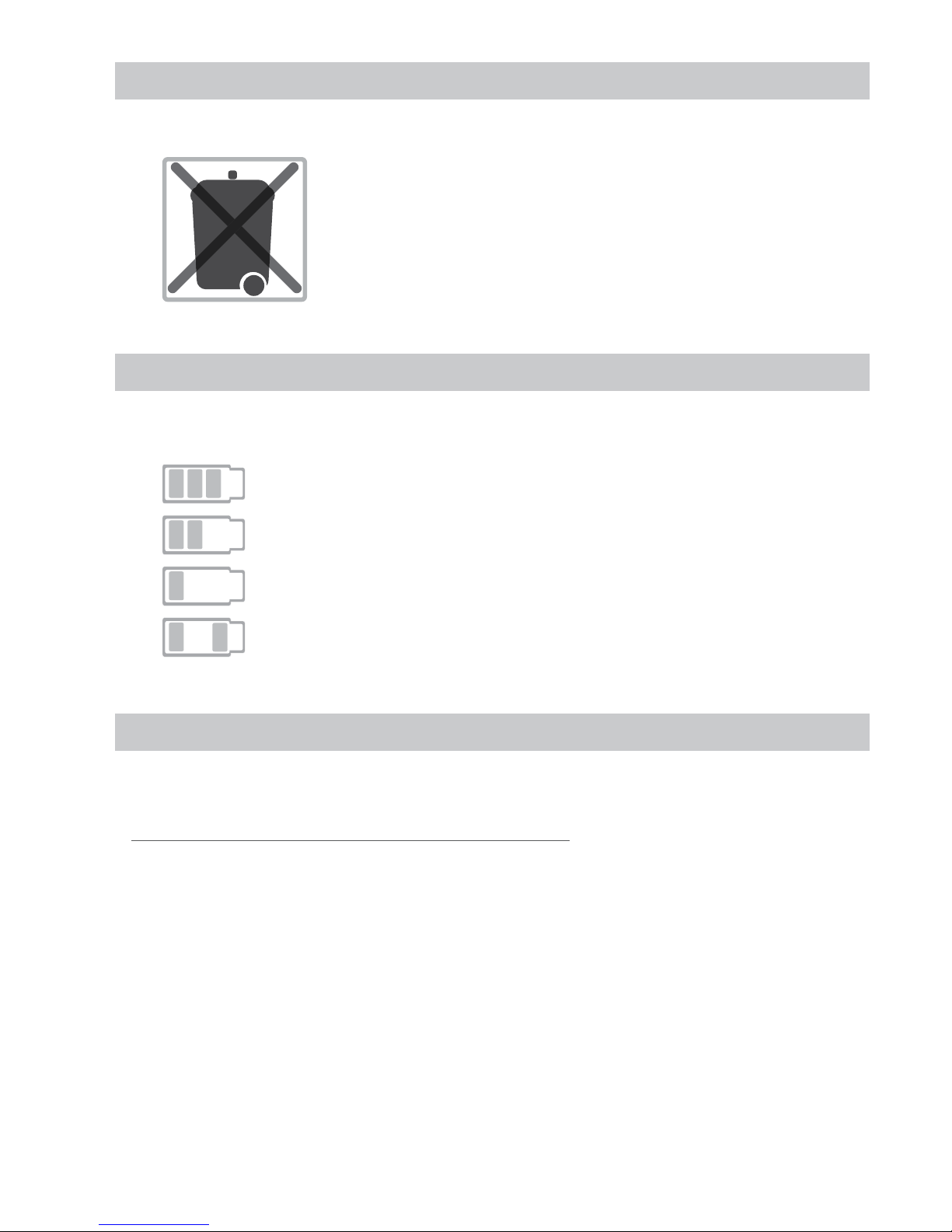
The GI410 has three battery indications (by LEDS on LED model).
HIGH battery level (100% - 70%)
MEDIUM battery level (70 % - 40%)
LOW battery level ( - 40%). You must connect the equipment to a power outlet.
During the charge (only LCD model)
During the charge (only LED model). Turn on high level and low level at the same time.
13. WARRANTY
This viewer is guaranteed against defects in materials or workmanship for a period of 1 year from the date of delivery.
Giropès, will be responsible for repairing the viewer during this period.
This warranty does not cover damage caused by misuse or overloading.
The warranty does not cover shipping costs (freight) necessary to repair the balance.
Page 41

41
ENUSER MANUAL GI400 / GI410
NOTES
Page 42

ENUSER MANUAL GI400 / GI410
42
NOTES
Page 43

43
ENUSER MANUAL GI400 / GI410
NOTES
Page 44

ENUSER MANUAL GI400 / GI410
44
Pol. Empordà Internacional Calle F. Parcela 15-16
17469 VILAMALLA - (Girona) SPAIN
T. (34) 972 527 212 - F. (34) 972 527 211
 Loading...