

Girard systems G-5000 User Manual
G-5000
SLIDE OUT AWNING
INSTALLATION SERVICE and REPAIR
REV.01272016
RV AWNING PRODUCTS
1361 CALLE AVANZADO, SAN CLEMENTE, CA 92673 (800) 382-8442 FAX (949)276-5500
www.girardrv.com

or similar is not covered by warranty.
Girard System s awnings may be o perated in light wind
and rain conditions. When periods of heavy rain and or
high wind are expected the awning must be closed. Never
leave the awning open and unattended.
Damage caused by wind and rain is not covered by
warranty.
All awnings must be closed prior to moving the vehicle for
any reason. As an extra safety precaution a visual check
that every awning is fully closed is required.
Damage caused by failure to comply with these
instructions is not covered by warranty.
Before using your awning, en sure that the area into which
the awning wil l be deployed is free of obstructions (Trees,
walls, pillars, posts, other ve hicles etc.)
Damage caused by collisions with any of the above
Page 2 of 16

CONTENTS
Installation Instr uctions …………………………………………………… ………………….…….. 3
Tools required …………………………………………………………………………………………… 4
Preparation for installation …………………………………………………………………………. 4
Bracket placement Chart ……….…….…………………………………………………………….. 5
Installation Sequence ………………………………………………………………….…………….. 6
Spring Tension Adjustment ………………………………………………………………………… 7
Lead Rail / Articulation Replacement …………………………………………………………… 8
Slide Brush Replacement ……………………………………………………………………………. 8
Spring Replacement ………………………………………………………………………………….. 9
Fabric Replacement …………………………………………………………………………………. 10
Fabric Care and Maintenance ………………………………………………………………. 11-12
G-500 Exploded drawing …………………………………………………………………….……. 13
Component Identification ….………………………………………………………………… 14-16
INSTALLATION INSTRUCTION S
Before beginning to install the awning please ensure the following;
• The vehicle is parked and leveled on suitable hard standing.
• Suitable precautions have been taken to protect the vehicle from accidental
damage.
• The area of the vehicle where the awning is to be installed has been prepared.
• Sufficient manpower, a minimum of 2 persons is required.
• Suitable protective clothing is wo r n by the persons doing the installation.
• Suitable and serviceable lifting and holding equipment should be used to avoid
personal injury.
• When mounting fixtures to the vehicl e be aware that the soft materials that the
skin of the vehicle is made from can be torn out or “Stripped” by the over
tightening of fasteners.
DO NOT OVER TIGHTEN FIXING BOLTS AND SCREWS.
• Make every effort to ensure that fa steners are mounted to the structural
framework of the vehicle not just the skin.
• Any holes made in the skin of the vehicle must be sealed with silicone sealant, putty
tape or similar product.
Page 3 of 16

ELEVATION DESIRED
NUMBER OF ARTICULATIONS
2 ½” to 3 ½”
3
3 ½” to 4 ½”
4
4 ½” to 5 ½”
5
TOOLS REQUIRED
•
Electric Drill
•
Drill bits: 1/8”, 3/8”, and 7/16”
•
Tape measure
•
(2) ladders
•
Chalk line
•
Flat head screwdriver (small)
•
Phillips screwdriver #2, #3
•
Allen wrenches: 5mm and 4mm
•
9/16” Open ended w rench
•
(2) tubes silicone caulking
•
Caulking gun
•
Keyhole saw
•
Double sided tape
•
Self-tapping screws #6 X ¾”
•
Self-tapping screws #12 X 1 ½”
•
3/8” Ratchet wrench
•
Girard tension tool.
Part#1511100-19T (Available on
request)
PREPARATION FOR INSTALLATIO N
1. Ensure that the overall length of the awning cassette is 3” longer than the width
of the slide out room.
2. Ensure that a sufficient number of mo unting brackets is available for the length
of the awning (Refer to bracket pl acement chart on page 5).
3. Ensure that the rubber weather seal is p r esent and long enough for the awning.
4. Ensure that the awning cover moves freely and cl oses correctly on the magnetic
latches.
5. Determine the vertical distance a bove the slide out room (Elevation) that the
awning is to be mounted. (Up to 5 ½”)This will determine the gradient of the
run off and the number of articulations needed between the fabric and the lea d
rail. (See chart below)
6. Ensure that there is a sufficient number of articulations to allow for the elevati on
desired.
Page 4 of 16
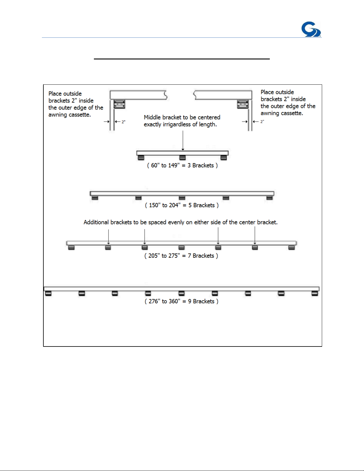
BRACKET PLACEMENT CHART
Page 5 of 16
 Loading...