

Girard Products GSWH-2 Technical Manual

1
Technical
Manual
Model: GSWH-2
Features:
• Demand Tankless Water Heater
• LP Gas / Induced Draft
• Constant Outlet Temperature
• Linear Gas Control Valve
• Electronic Gas Modulation
• Microprocessor Controls
Operation
Functional Tests
Troubleshooting
Service and Maintenance
Service must be performed by a
certif ied installer, service agency
or gas supplier.
This water heater is certified for
installation in Recreation Vehicles
(RV’s) and is not for use in
Marine
or Space Heating
Applications
.
For service and spare parts:
Girard Products LLC
2515 Lombardy Dr.
Goshen, IN 46526
866-559-1221
Girard Products LLC, 1361 Calle Avanzado, San Clemente CA 92673 USA
Patent Pending
2
TANKLESS WATER HEATER - Model GSWH-2
•
Use with Universal LPG only.
CONSUMER SAFETY WARNING!
•
Shut off all
gas
appliances and pilot lights when
refueling.
•
Turn gas OFF at
the LP tank when vehicle is in motion. This disables all gas a
ppliances and
pilot lights. Gas appliances must never
be
operated while vehicle is in
motion.
•
LP tanks must
be
filled by a qualified
gas
supplier
only.
•
Should overhea
ting occur, turn gas OFF at
the LP tank and turn the opera
ting switch to the
OFF
position.
In a conventional installation the Girard Tankless Water Heater is dependent on and connected to
:
1. Input Water flow:
The
RV’s
cold water system deriving its water input from a pressurized (45 PSI or greater) source such
as a shore
connection or
an
RV
water pump connected to the
RV’s
fresh water storage tank.
A steady water flow (no pulsating) w i l l
ensure a consistent temperature and
performance.
Water Pressure regulators are commonly recommended but they often decrease water flow to unacceptable levels.
Water filters are highly recommended to keep sediment out of the plumbing system but the need to be maintained or they can restrict water f low.
Winterization by-pass kits are not recommended in a tankless water heater systems. The can cause a number of plumbing issues that will affect
the operation of the water heater.
City water connections at RV parks can have low or varying water pressure. If this condition occurs and cannot be resolved, then we recommend
filling the fresh water tank and using the onboard water pump.
2. Output Water flow:
The
RV’s
hot water system (i.e. faucets and
shower).
Purge all air from the plumbing system using both the water pump and city water source. Air in the plumbing can cause intermittent heating
operation errors.
Pressure is important but actually water flow is critical to the operation of a tankless water heater. The longer the water stays in the water heater
the hotter it will become. The water flow is dependent on the plumbing and fixtures of the RV. The length of plumbing, the amount of elbows
and the restrictions in the faucets and show heads. Experience has shown us that the average RV water flow is between 1 and 1.4 Gal lons per
Minute. This water flow will give you the optimal operation of the water heater.
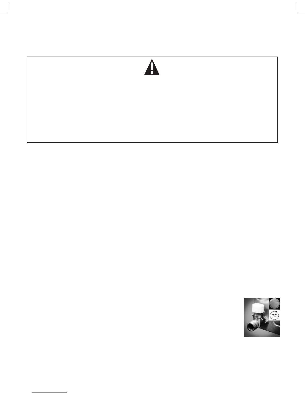
The water heater is equipped with a water control valve to help maintain this optimal water flow especially in winter
conditions where input water temperatures below 45 degrees the. The water heater is shipped with the water control in
the maximum flow setting.

3
3. LP Gas System:
The
RV’s
LP Gas system capable of supplying its rated
42,000
BTU
requirement.
The Girard Products model GSWH-2 introduces a new generation of smart tankless water heater designed specifically for Recreation
V
ehicles (RV).
Its configuration and size are consistent with the tank based
RV
water heaters currently in
use
and is designed for
OEM’s
and after-market
use
by the RV Industry.
LP system issues can occur that can adversely affect the operation of the water heater so it is important that the LP system is
maintained.
Gas pressure drop test requirements vary from state to state but the RVIA regulation states that gas system should m ain t ain 8 ” WC
for 3 minutes.
LP tank and bottles must be purged correctly when filled , especially upon the first fill, to ensure that all of the air has been
eliminated from the LP cylinder. If this is not performed gas appliances will not work or not perform as required. When the
cylinders are not filled properly we often see insufficient temperature rises from the wat er heater.
Gas p ress u re o f 11” WC i s th e rec o m men d ed m i nim u m p r e ssu r e fo r the p rop e r ope r a tio n of t h e w a ter h e ater . Th i s tes t mus t be
performed with a minimum of half the gas appliances operating .
Col d we a t her c o ndi t i ons w ill a f fect t he o u tput BTU ’ s of t he LP cylinder. The smaller the cylinder the less output can occur.
Debris and a build-up of oil in the LP plumbing can restrict gas flow to the appliances.
4. 12VDC Power:
The
RV’s
12VDC electrical power system. Proper 12VDC and ground is required for proper operation of the water heater.
Low voltage or bad voltage will cause non-operation or failure of the water heater.
The water heater will not function when input voltage drops below 10VDC. When this happens a red LED will illuminate on the water
heater control board.
Over the years we have seen a drastic improvement with power converters and inverters. The poor power output of an older linear
style converter can cause issues with modern electronics. If using this water heater with older converters we recommend wiring
through the battery or on the filtered side of the converter so the battery can act like a capacitor and filter the voltage.
Understanding How
the
Girard Tankless Water System Works
The Water Heater’s
microprocessor based controller (Control
Board)
receives from electronic sensors the data it needs to
decide each step of the Model GSWH-2
operation.
1. The
User Control Panel (UCP)
displays
each phase of the Water Heater’s
opera
tion and receives from the user the operational parameters
desired:
• ON/OFF to
activate
• Desired outlet
temperature
2. V
erify that
all components are in working order and that it is
safe to start the unit upon sensing the minimum amount of water
flow
required (.70 GPM +/- 10%)
3.
The water heater will continue operation
as
long
as:
•
The water flow
is above the minimum required
•
The presence of flame is verified
•
No unsafe condition
develops
4. The UCP will provide the user with
a
visual indica
tion of the opera
ting conditions
illuminating
the appropriate
icon and displa
ying
the current outlet
temperature:
•
Fan icon on: Blower
operating
•
Flame icon on: Burner is lit and flamed is
detected
•
Shower Head on: Water is flowing
4
5. The button marked “C/F” determines if the temperature is displayed in °F or °C
degrees
6. Whenever the “UP” or “Down”
are pressed the display shows the
set temperature.
7. If an unsafe condition is encountered and the unit shuts off, the display
will show an Error
Code
corresponding to the actual condition that caused the
unsafe condition.
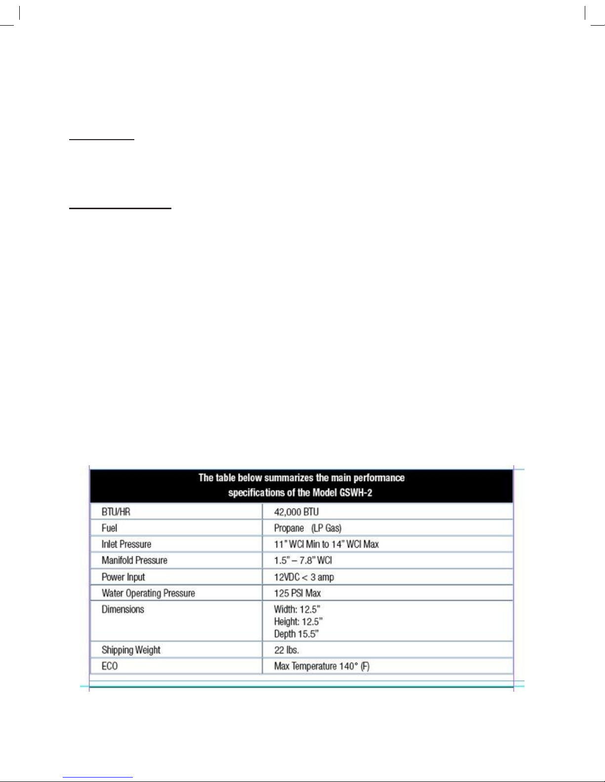
The Model GSWH-2 can
be
operated from the User Control Panel (UCP) which includes
the Power
ON/OFF
switch.
The model GSWH-2
can be
operated in
two
different
ways:
1. Operate
like
a Tank Water Hea
ter. The user turns on the hot water and adds cold water to achieve
the desired Hot water temperature.
2. Select the desired temperature by adjusting temperature setting up (^) or down
(v). The UCP
settings are from
95° (C) to
124°
(C). The unit will
maintain the
set temperature.
Note – The recommended and Factory setting is
115°
(F).
For normal
operation:
1.
Turn on the power. The panel will light and will
display the current temperature
at
the inlet of the
unit.
2.
Press a temperature selection arrow (up or down) to
see
the current
set temperature.
3.
Adjust the
set
temperature to your
preference.
4.
Turn on the
faucet.
WARNING!
It
is dangerous to operate a Tankless Water Heater unattended. This may occur accidentally
if
a sufficient
leak develops in the water system or if a faucet is left open. For this reason, The GSWH-2
will
automa
tically
turn off after operating for
20
minutes and displays Error “En” on the Display.
5
Troubleshooting & Repair Guide
Sequence of Operation
a. Tools required:
1. Multi-meter 4. Thermocouple readout or Thermometer
2. Gas pressure manometer 5. Wrenches (23MM, 19MM, 15MM)
3. Screwdrivers (Slot and Phillips heads) 6. Pliers (Regular and Needle Nose)
b. Installation verification:
Op
en the door and verify that:
1. There is no obstruction to the air flow within the housing (Objects, dirt or other)
2. The Exhaust tube is free and clear of any obstruction (Leafs, insect nests, other)
3. Verify that the water inlet valve is wide open
4. Remove the Fuse located below the ON/OFF switch and verify that it is not blown.
5. Open lid of Control Box pulling on the left edge
6. Verify that the board is clean and shows no signs of burns or overheating around any component
7. Verify that all connections are in place and solid (See Figure 4 and Figure 5 below)
8. Turn ON power switch
9. Verify that the indicator light comes ON.
10. Verify that the unit is connected to 12VDC power supply using the Voltmeter (See section d.)
11. Verify that there is gas available (Tank not empty and lines full).
When the Installation verification is completed open a faucet to operate the unit.
If any Malfunction occurs during operation, refer to the following illustrations to gain access to all major components of the unit
and proceed to the troubleshooting procedures (see below in this manual). Unit cannot be operated without firewall in place. Make
sure to determine a probable cause before gaining access to the major components.
6
Static Operation – No Water Flow
Input 12VDC Power:
Red wire positive and black wire ground to back of the water heater
Confirm that you have a good power source with filtered voltage. Older linear type converters can cause issues with the
operation of this more advanced board.
12VDC Ground Black wire run direct to board through power connector
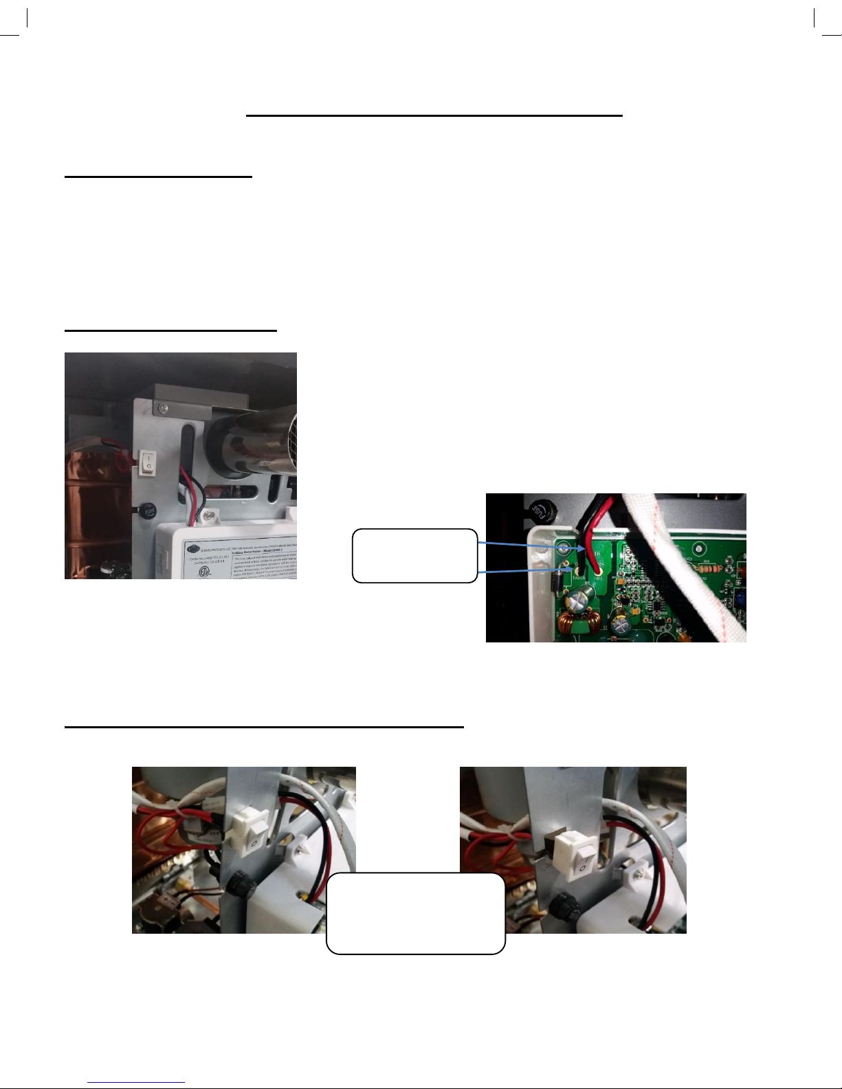
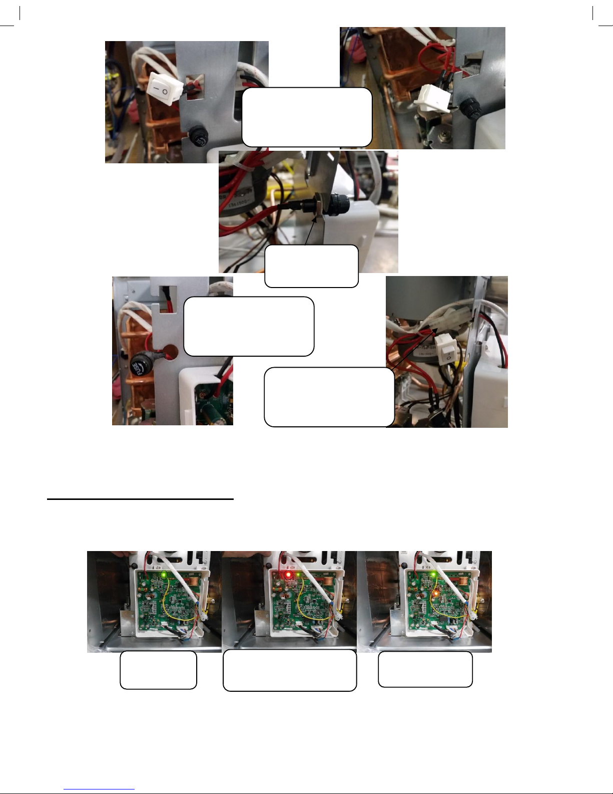
Power Switch and Fuse:
12VDC Red wire positive to the power switch.
12VDC Red wire from the switch to the fuse.
12VDC Red wire from the fuse to the power connector.
12VDC Red Wire from the power connector to the board.
Power between the red and the black wires eliminates the fuse, switch and
incoming power supply. Ensure the ground is good.
Removal and replacement of fuse and switch:
Black Negative
Red Positive
Push down on top tab and
up on the bottom tab and
pull forward
7
Operational Indicator LED’s
These LED’s indicate proper voltage and operation of the water heater. Voltage below 10VDC will cause the red
light to illuminate and the board will not engage operation of the water heater.
Pull Wires through cut
out. Note: Wires are
soldered to switch
Loosen 15 mm
nut on the fuse.
Pull fuse forward and then
pull wires through the cut
out.
Power wire connector for
incoming 12VDC to the
Board
Green LED Up
to 17VDC
Red LED Below 10VDC No
Operation When This Occurs
Amber LED during
operation
8
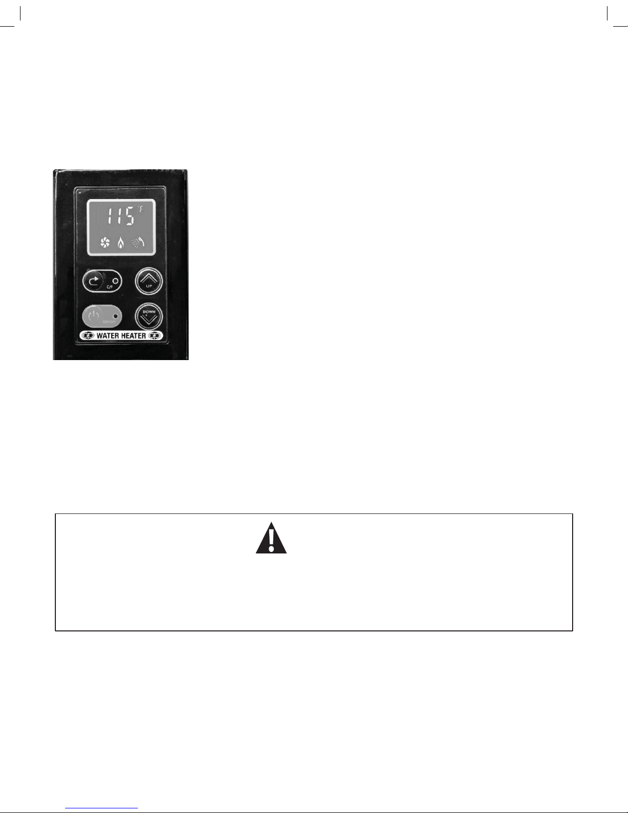
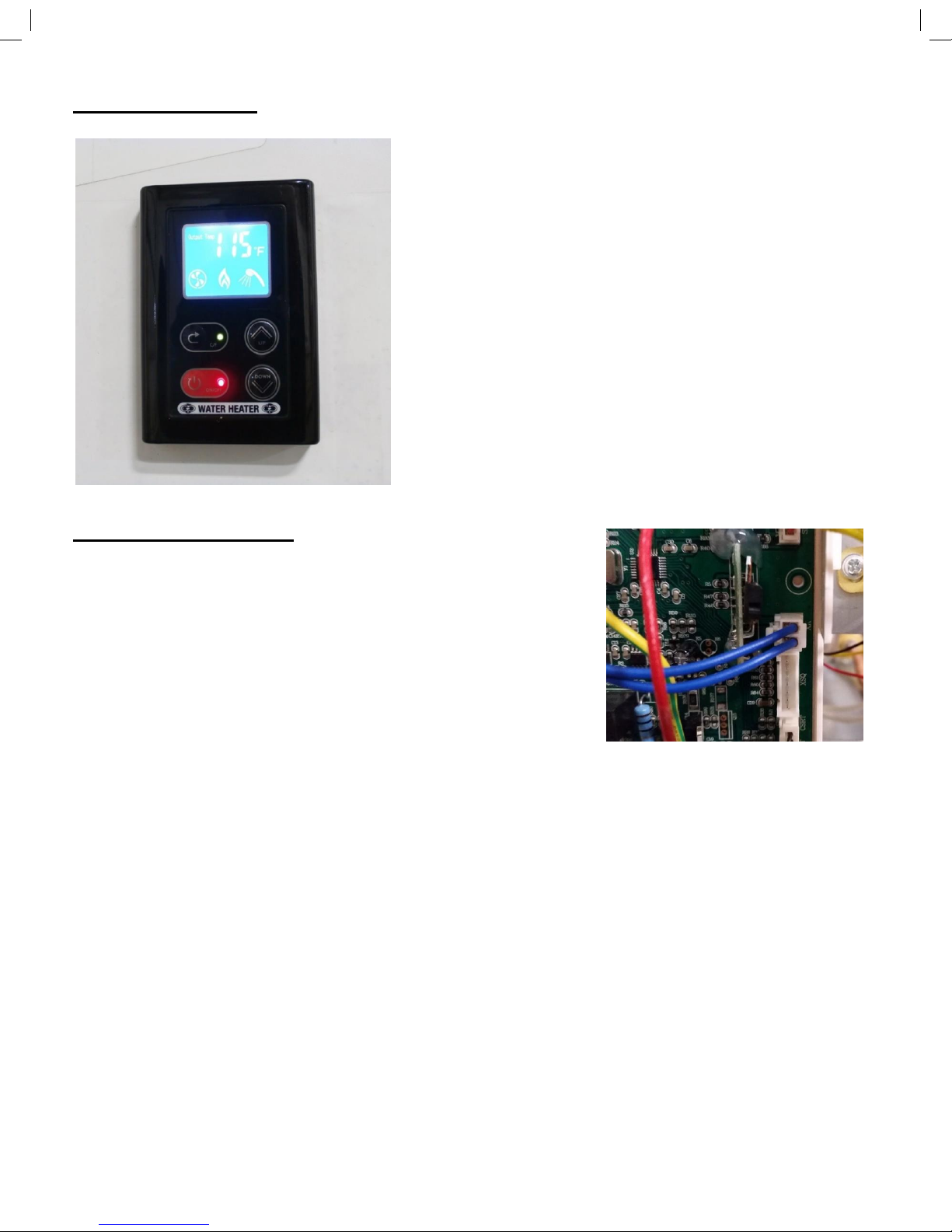
User control panel
Recommended Setting 115 degrees.
Icons showing temperature setting, Output Temperature, Fan, Flame
and Water Flow. These are important to troubleshooting.
Confirm that you can change the temperature setting on the UCP.
Wire connections.
Damage to the control board may occur if the blue wires between the
Control board and the UCP are connected to ground or 12VDC or
crossed.
No Operation of the UCP
1. Confirm operation of the UCP. Turn on switch, back light operation, change
the temperature setting.
2. Confirm good power and ground to Control board and the green light is on.
Check the wire connection at the XK terminal.
3. Check voltage between the 2 wires at the connection of the UCP. You
should find a fluctuating voltage of 9 to 11VDC.
4. Check voltage between the 2 blue wires at the XK Connector. You should find a fluctuating voltage of 9 to 11VDC.
5. If there is no power to the UCP but it is present at the board then there is a wiring issue between the UCP and the control
board.
6. If you have no power at the UCP and no power at the control board then the control board is bad. But there may still be a
wiring issues that may have caused the board to fail. Eliminate before replacing the control board.
7. If the wires are crossed then the board next to the XK Connector will get hot. Discoloration will occur on the board and
the control board may fail.
8. If the wiring between the UCP and the control board is shorted to ground or 12VDC then discoloration may occur and
you will get erroneous readings at the UCP and the control board may fail.
9
Hot water flow on - Pre-Trial for Ignition
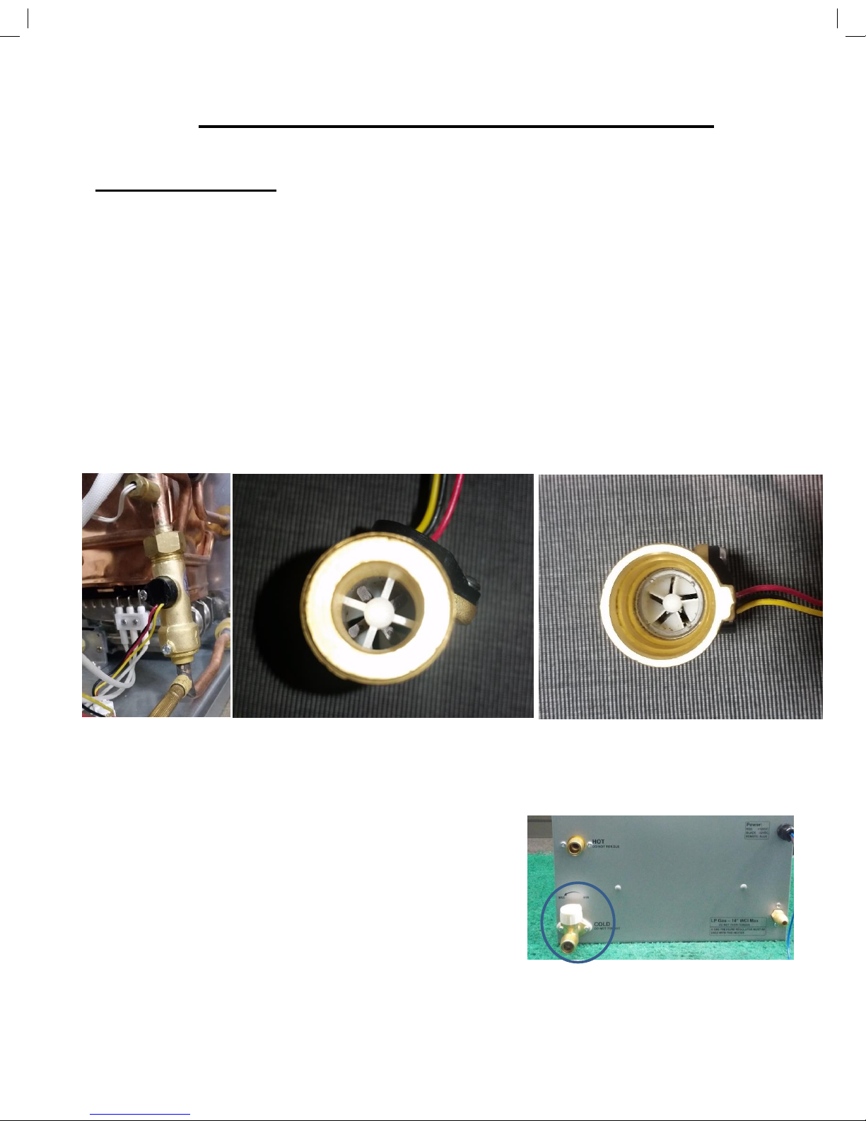
Water Flow Sensor:
As the water flow increases the board will increase the BTU’s to compensate for the lower temperature rise. As the
water flow decreases the board will decrease the BTU’s to compensate for the higher temperature rise.
The water flow sensor or water flow meter gives the actual water flow measurement to the control board. As water flows
through the flow meter. The fins in the flow meter spin the water through the flow meter which turn the magnetic impeller.
The board sends 5vdc to the flow meter. The Reed switch on the side of the flow meter turns on and off quickly as the
magnetic impeller turns past it. This changes the “frequency” of the power coming back to the board. The board actually
reads the “frequency” determining how fast the impellers are turning. The flow meter cannot be tested with a resistance
check.
The simplest way to determine that the board has confirmed that the water flow meter has engaged is by examining
UCP. If the water flow icon (a shower head symbol) is active on the User Control Panel when the hot water faucet is
turned on then the flow meter can be eliminated.
The control board starts the operation of the water heater when the water flow exceeds .80 GPM (+/- 10%).
Confirm the actual water flow by timing how long it takes to fill a gallon container. Divide 60 seconds by the seconds
measured to come up with the GPM.
If the water flow is too low then you will need to inspect the
Water Control
V
alve
adjustment on the water heater. Ensure that it is opened all of the way
up.
Other causes of reduced water flow are plumbing restrictions, pressure
regulators, water filters and insufficient shore or pump water pressure.
10
Mixing of hot and cold water will restrict the water flow through the water heater. When mixing hot and cold water at the
faucet you will start to diminish the flow through the water heater. When the flow is low enough the board will no longer
sense that there is enough flow of water and the board will turn off the operation of the water heater.
Other plumbing issues can cause a mixing of hot and cold water. Winterization bypass kits may be set incorrectly causing a
mixing hot and cold water. Also, in many cases, if you turn on the outside shower valves and turn off the shower head you
will mix hot and cold water through the system.
Another plumbing issue is the polarity of the water flow through the water heater. If the plumbing lines are reversed then the
impeller in the flow sensor will not activate. The fins in the flow meter spin the water which spins the impellers. If water is
going the wrong way through the water heater the impellers will not spin and the flow meter will not operate.
We have seen grease like deposits on the impellers of the flow meter causing the flow meter to read slower the actual water
flow is through the water heater. If the water heater will not turn on above .80 GPM and plumbing issues are eliminated then
the flow meter will need to be changed.
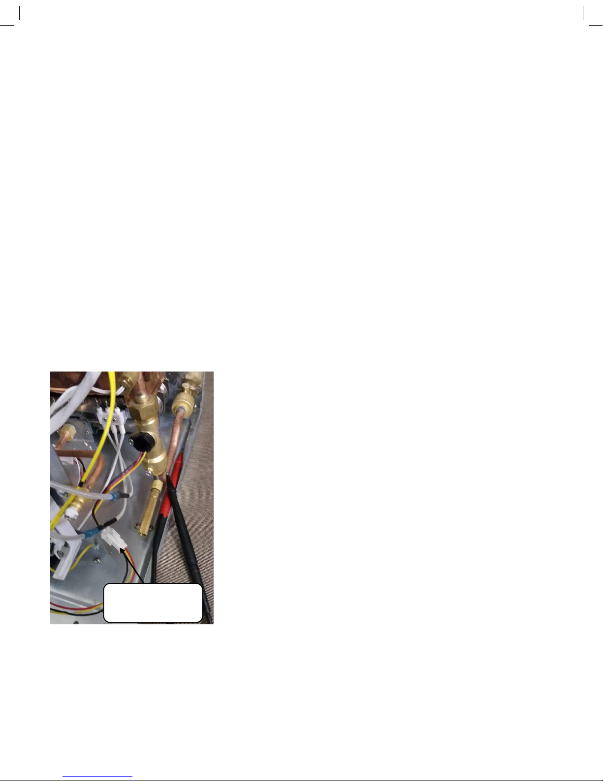
Voltage test
This test will confirm if the impellor is turning but will not tell you the actual water flow. If you do not see a voltage drop to
approximately two volts then 1) the impellor is jammed 2) the water is not flowing through the water heater 3) the water is
flowing the wrong way through the water heater 4) the Reed switch of the flow meter has malfunctioned.
Water flow off:
5 VDC between the black and the red.
5 VDC between the black and the Yellow.
Water Flow On:
5 VDC between the black and the red.
2.6 VDC between the black and the yellow.
Note that if the flow meter fails it will not generate a fault code. The water
heater will simply not turn on.
Water flow Sensor
wire connector
11
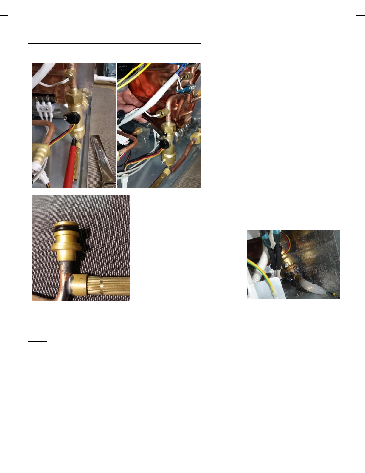
Removal and Replacement of the Flow Meter
1. Remove the set screw on the front of the flow
meter.
2. Loosen the compression fitting on the top of
the flow meter using a 5/16” or a 23mm
wrench.
3. Twist the flow meter plumbing and pull the
flow meter upward. Ensure the top O ring is
not damaged or discarded.
4. After removing the flow meter check the integrity of the bottom O ring.
5. When reinstalling the flow meter ensure
it is fully ceded to avoid water leaks.
Reinstall the 23mm compression fitting.
Do not overtighten.
6. Reinstall set screw.
7. Check for leaks.
ECO
AKA: Emergency Cut Off, Energy Cut Off, and High Temperature Limit Switch. The temperature setting
that the ECO turns off at is 140 degrees.
Although Purging of air out of the plumbing is less crucial with this model it is still important to prevent
intermittent overheating or erroneous heating issues.
 Loading...