

Girard Products GSWH-1M, GSWH-1M REVISION 1 Owner's Manual

Owner’s Manual
Girard Products LLC, 1361 Calle Avanazado, San Clemente CA 92673 U.S.A
Owner’s Manual Part No. 1GWH9407, REV. 1
CAUTION:
Read and Follow all
the Safety Rules and
Instructions before
operating this Appliance.
Demand Tankless Water Heater
LP Gas
Power Blower Induced Draft
Gas Modulation Control
Installation and service must be
performed by a recommended
installer, service agency or gas
supplier.
This water heater is certified for
installation in Recreation Vehicles
(RV’s) and is not for use in Marine
or Space Heating Applications.
Model: GSWH-1M
REVISION 1
1Page
• Installation
• Operation
• Service and Maintenance
Patent Pending
CSA Approved
TANKLESS WATER HEATER - Model GSWH-1M
Installer/Customer Responsibilities
• Installation and Service must be performed by a Girard Products LLC
recommended installer, service agency or gas supplier.
• Do not attempt installation as a Do-it-Yourself project
• Read and observe all safety rules
• Shut off gas appliances and pilot lights when refueling.
• Keep these instructions and warranty for future reference
• Follow all applicable State and Local Codes
• Follow a regular schedule of maintenance as outlined in this manual
2Page
This is the safety alert symbol. It is used to alert you to potential
personal injury hazards. Obey all safety messages that follow this
symbol to avoid possible injury or death. Failure to follow these
alerts could result in Fire, Explosion or even Death.
WARNING – FIRE OR EXPLOSION
WARNING: These instructions must be followed exactly, or a re or explosion
may result causing property damage, personal injury or death.
• Do not store or use gasoline or other ammable vapors and liquids in the vicinity of
this or any other appliance.
• FOR YOUR SAFETY --- WHAT TO DO IF YOU SMELL GAS
• DO NOT attempt to light any appliance.
• DO NOT touch any electrical switch, or use any phone or radio in the vehicle.
• DO NOT start the vehicle’s engine or electric generator.
• Evacuate all persons from the vehicle.
• Shut off the gas supply at the gas container or source.
• Contact the nearest certied service technician or gas supplier for repairs.
• If you cannot reach a certied service technician or gas supplier, contact the
nearest re department.
• DO NOT turn on the gas supply until the gas leak(s) has been repaired.
• Installation and Service must be performed by a Girard Products LLC
recommended installer, service agency or gas supplier.

USA AND CANADA - FOLLOW ALL APPLICABLE STATE AND LOCAL CODES
IN THE ABSENCE OF LOCAL CODES OR REGULATIONS REFER TO CURRENT
STANDARDS OF:
• Recreational Vehicles ANSI A119.2/NFPA 501C.
• CSA standard Z240 RV Series, Recreational Vehicle.
• Park Trailers A119.5
• National Fuel Gas Code ANSI Z223.1 and/or CAN/CGA B149 Installation Codes
• Federal Mobile Home Construction & Safety Standard, Title 24 CFR, part 3280, or
when this Standard is not applicable, the Standard for Manufactured Home Installations
(Manufactured Home Sites, Communities and Set-Ups), ANSI A255.1 and/or CAN/
CSA-Z240 MH Series, Mobile Homes.
• National Electrical Code ANSI/NFPA No. 70 and/or CSA C22.1
3Page
CRITICAL INSTALLATION WARNINGS
• Installation and Service must be performed by a Girard Products LLC
recommended installer, service agency or gas supplier.
• This product is not designed for Do-it-Yourself Installation.
• Install ONLY in recreation vehicles (RV’s). RV’s are recreation vehicles designed
as temporary living quarters for recreation, camping, or travel use having their own power
or towed by another vehicle. This water heater is NOT designed for Marine or Space
Heating applications
• All combustion air must be supplied from the outside of the RV, and all products of
combustion must be vented to the outside of the RV.
• DO NOT vent water heater with a venting system serving another appliance or
to an outside enclosed porch area.
• DO NOT modify water heater in any way. This is dangerous and will void the
warranty.
• DO NOT alter water heater for a positive grounding system.
• DO NOT HI-POT water heater unless the electronic ignition control (circuit board) has been
turned ‘OFF’ (Power switch is in “Off” position)
• DO NOT use battery charger to supply power to water heater even when testing.
• Protect building materials from ue gas exhaust.
• Install the water heater on an exterior wall, with access door opening to the outdoors.
• DO NOT lift the water heater or carry it by holding the blower assembly support bracket/
exhaust tube.
• DO NOT modify the length of the wires protruding past the strain relief from the
rear of the housing.
INSTALLATION
The following instructions apply to the most common type of installation for Girard Products
GSWH-1M water heater. Consult with Girard Products, LLC technical support or engineering
department if you have any additional questions regarding your specic installation/application.
Select a suitable location
The water heater is designed to be installed on a oor or a xed platform with access to water,
gas and electrical connections from the back. It is recommended that the GSWH-1M be located
as near the center of the coach as possible.
DO NOT INSTALL IN AN AREA WHERE ONE OR BOTH THE INLET AIR VENT AND FLUE
VENT CAN BE COVERED WHEN A DOOR OR ACCESS PANEL OF THE VEHICLE IS OPENED.
DO NOT INSTALL WHERE THE FLUE VENT IS CLOSER THAN ONE FOOT IN ALL
DIRECTIONS FROM ANY WINDOW OR OPENING INTO THE VEHICLE.
DO NOT INSTALL THE WATER HEATER OR ANY OTHER APPLIANCE WHERE IT CAN VENT
INTO AN AREA COVERED BY AN AWNING, CANOPY OR ANY OTHER ENCLOSURE.
(Note: The water heater can be installed under an RV roll-out/retractable type awning providing
the awning does not have an enclosure such as a screen room and/or some type of “walled
enclosure”)
4Page
WARNING! CAUTION!
• Improper installation, adjustment, alteration, service or maintenance can cause
property damage, personal injury or loss of life.
• Installation and Service must be performed by a Girard Products LLC recommended
installer, service agency or gas supplier.
• This product is not designed for do-it-yourself installation.
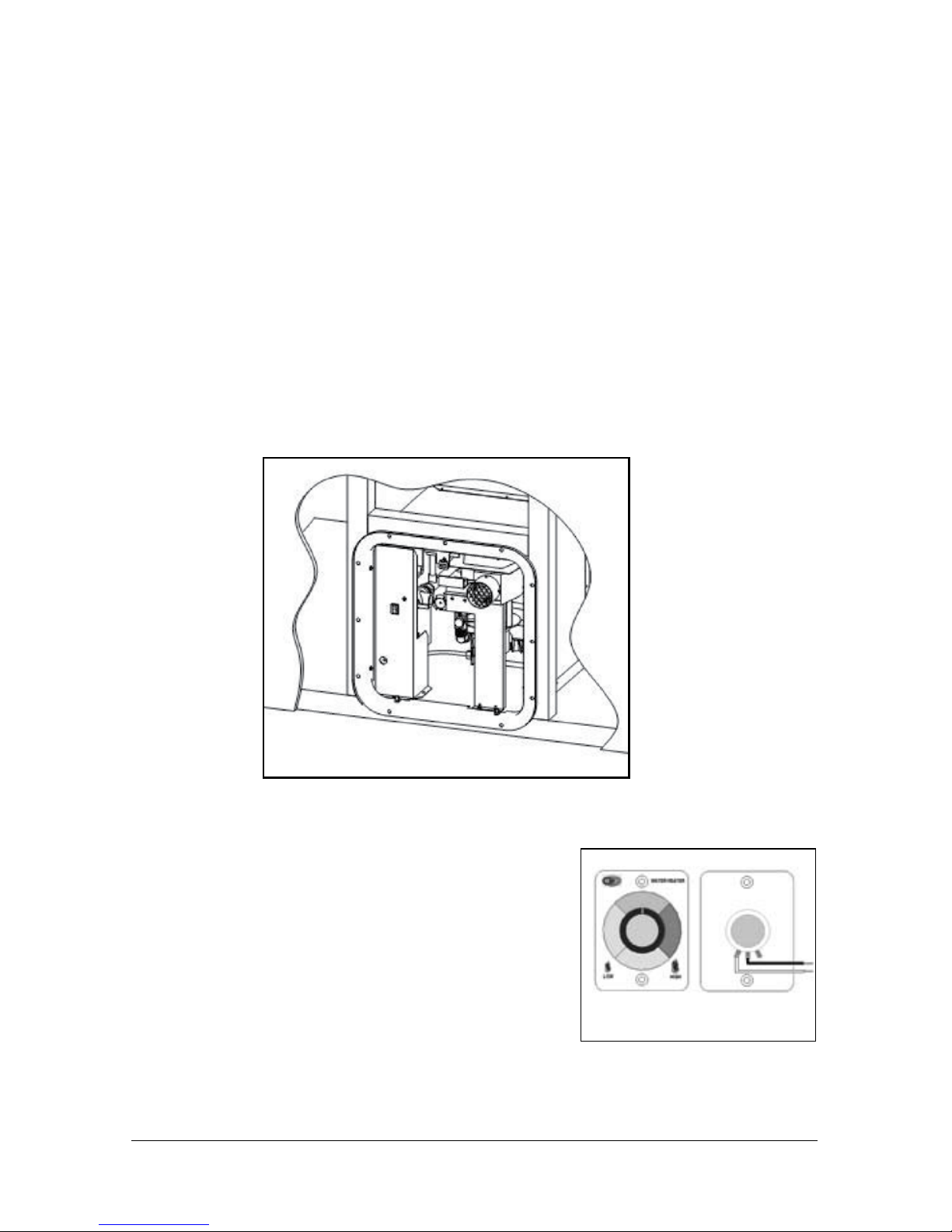
• DO NOT lift the water heater or carry it by holding the blower assembly support
bracket/exhaust tube (Figure 1).
IMPORTANT!
• For proper operation this water heater requires a minimum water ow of 1.0
Gallon per Minute (gpm) for each Hot Water faucet it supplies.
Site Preparation
To install on carpeted area you must install a metal or wood panel under the water heater that
extends at least 3 inches beyond the width and depth of the unit. If water leakage can result in
damage to the adjacent area, install a drain pan that can be drained to outside of the vehicle,
under the water heater.
Verify that a clearance of 1 inch will remain after installation between the top surface of the
water heater and any combustible material. 0 inch clearance is acceptable for the sides.
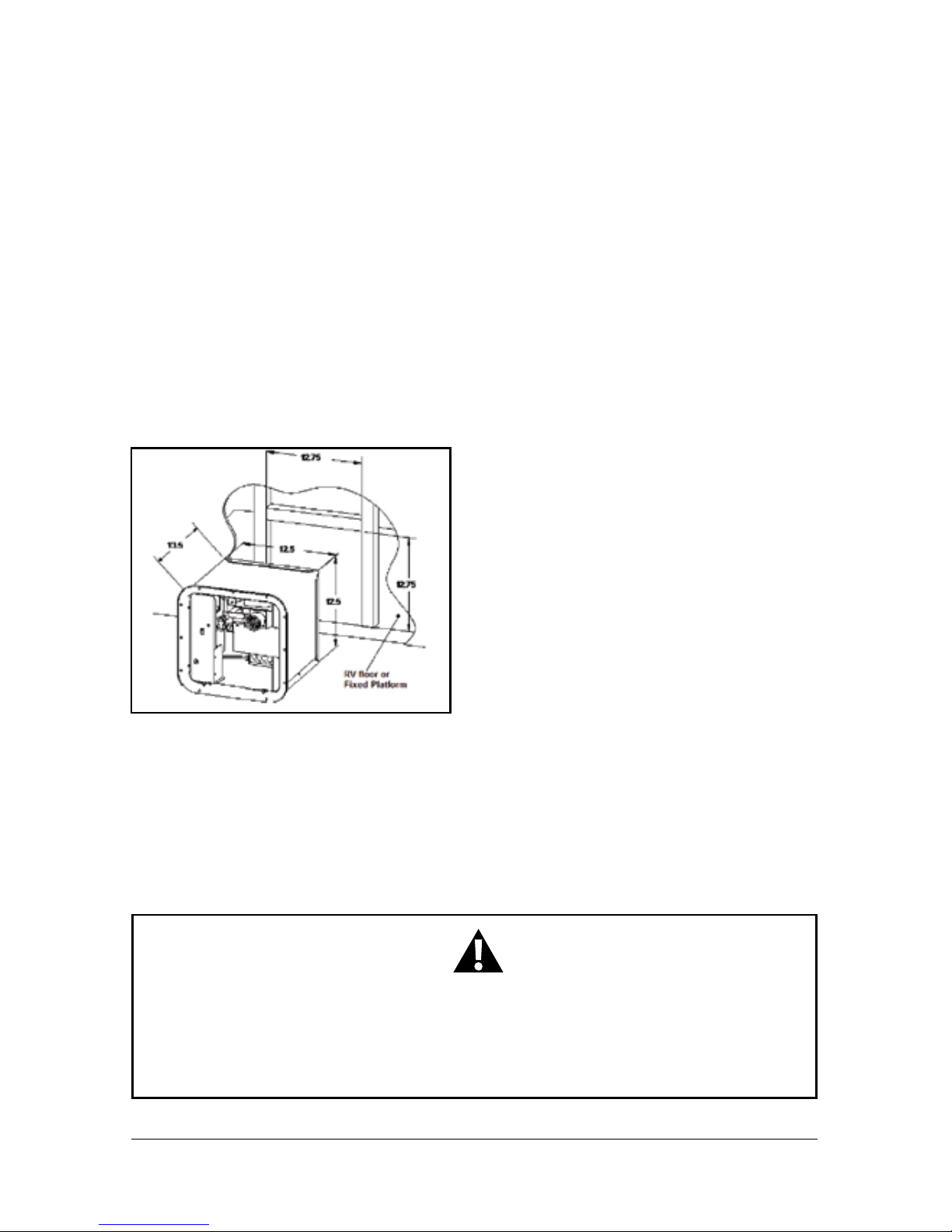
Make sure that the front edge of the opening is surrounded by a solid frame to rmly anchor the
water heater; if needed, build an appropriate frame using 2” X 2” elements (Figure 1)
The rough opening for the GSWH-1M should be 12.75” X 12.75” with right angle corners. The
exterior wall opening must be the same dimensions with no radius corners.
Water Heater Installation
Remove the water heater from the box by grasping the metal sides of the housing and lifting
upward until it is free of the box.
5Page
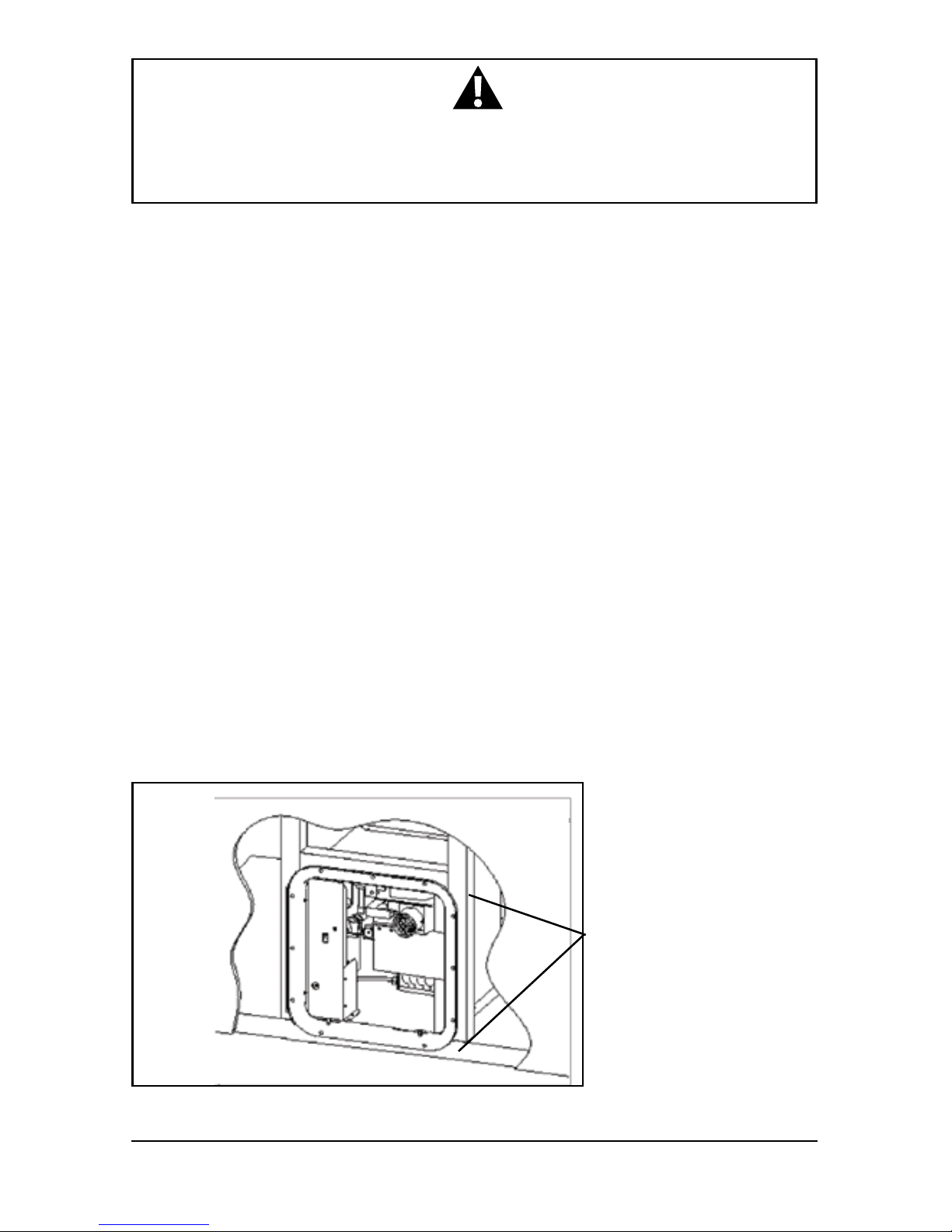
Ensure that water and gas connections from
the vehicle are in place for installing the
unit. Allow sufcient length and exibility
in the water and gas lines to reach the
connections while the unit is partially
inserted into the opening.
Figure 1
IMPORTANT!
• Lifting or moving the water heater using the Blower Assembly Support
Bracket/Exhaust Tube (Figure 1) may result in improper alignment of the vent
and/or improper alignment of the Sail Switch.

Partially insert the water heater into the opening and connect both Hot and Cold water lines to
the appropriate ½”NPT ttings. Connections can be made using PEX swivel nut adaptors with
NPS straight threads and a cone seal or with a standard ½”FPT nut. The PEX swivel nuts require
only hand tightening. (Figure 2, page 6).
Connect the gas to the 3/8” LP Gas compression tting on the back of the Water Heater (Figure
2). Use two wrenches to tighten the compression tting to avoid damaging the unit.
Use additional caulking if needed to complete a permanent seal of the gas line with the housing.
6Page
PRODUCT DAMAGE!
• Excessive torque will damage the Cold Water and Hot Water Inlets.
DO NOT over tighten.
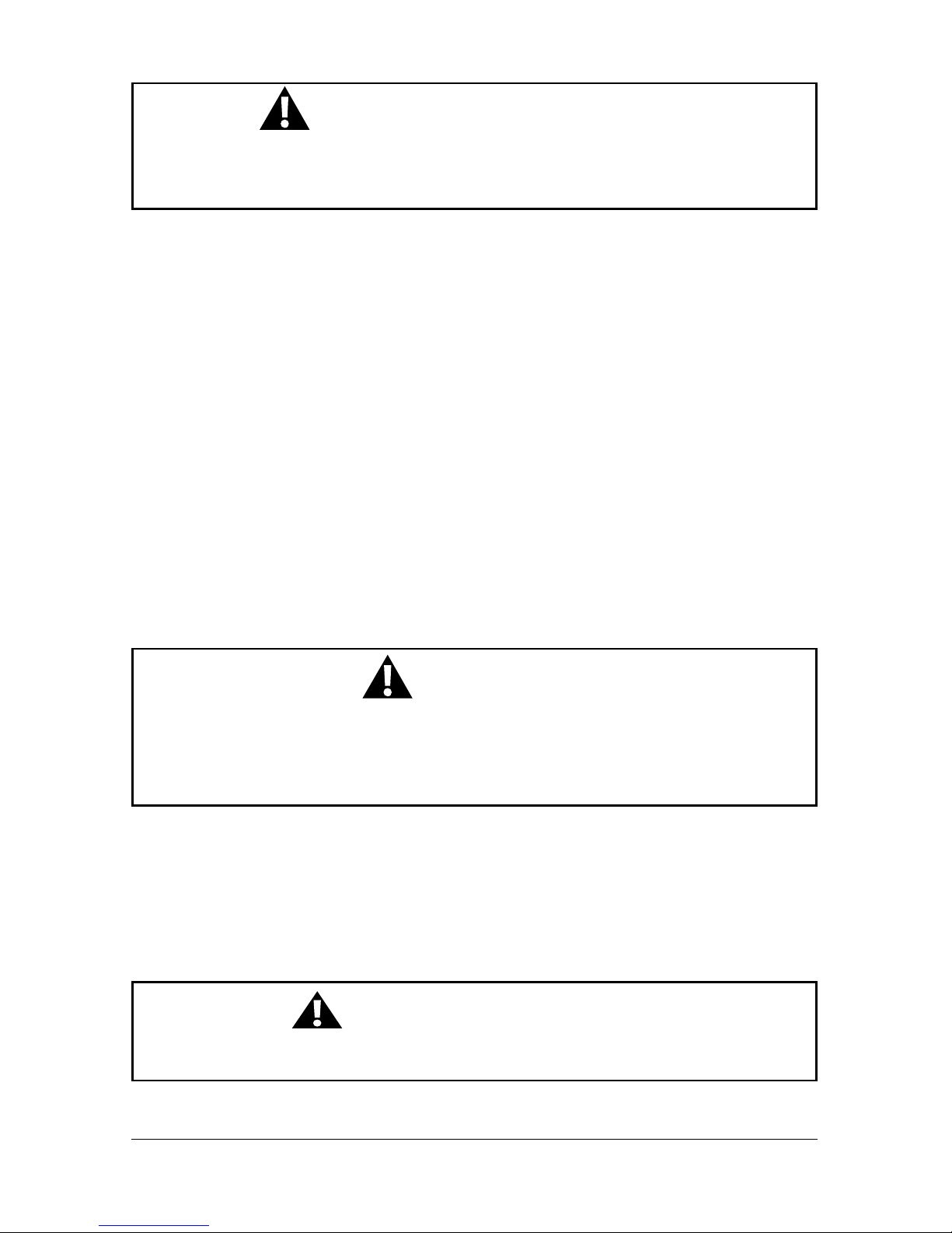
IMPORTANT! CRITICAL INSTALLATION
• DO NOT cut any wires.
• The length of the external wires, those wires extending beyond the strain relief
from the rear of the housing (Figure 2), must NOT be shortened for any reason.
Shortening these wires will prevent the removal of the Control Housing during
servicing and/or testing.
Figure 2
A: Installation of water heater with separate ange
1. Complete the “skin” application to the vehicle’s outer wall.
2. Position water heater housing into the frame opening with the front edge aligned
evenly to the exterior wall (See Figure 3).
3. To prevent water and air leaks apply sufcient caulking around the entire frame
opening and the exterior edge of the water heater housing. Use a suitable caulking
material that will result in a permanent seal between the water heater and the
vehicle’s frame.
4. Press the side walls of the water heater housing rmly against the frame to
expel any bubbles and ensure a good bond.
5. When ready to proceed, apply additional caulking or butyl tape to the back of
the door ange that will contact the RV sidewall around perimeter of the opening.
6. Insert the door ange into the water heater housing and press the ange rmly
against the sidewall.
7. Secure the ange to the vehicle using No. 8 - ¾” at head screws through each hole
along the perimeter. Verify that a tight seal exists between the side wall and the
ange. If not, repeat above steps.
8. Align each hole along the inside frame of the ange with the corresponding holes in
the water heater housing and secure to the frame using No. 8 - ¾” at head screws
using two screws per side.
9. Remove any excess caulking and clean all surfaces.
7Page
NOTICE
• If you wish to install the ange as an integral part of the water heater housing
proceed to B: Installation of water heater with Integral Flange (below).
Apply caulking
along each side.
Figure 3
B: Installation of water heater with integral ange
1. Protect the side wall with masking tape or other suitable means to insure that it is not
damaged while installing the water heater.
2. Position the water heater so that the front edge extends from the opening approximately 2”
and insert the door ange into the housing.
3. Permanently attach the ange to the housing using stainless steel screws or stainless steel
rivets with recommended grip range of .188” to .129” and hole size of .129” to .133”.
4. To prevent water leaks apply a good amount of caulking or butyl tape on the sidewall around
perimeter of the opening that will be covered by the ange and along the front edge of the
housing that will contact the mounting frame.
5. Slide the water heater in place into the opening and press the door ange
against the sidewall.
6. Secure water heater housing unit to the vehicle using No. 8 - ¾” at head screws through
each hole in the door ange (Figure 4). Verify that a tight seal exists between the side wall and
the ange. If not, repeat above steps.
8Page
Figure 4
C: Installation of 12VDC Power and Gas Modulation
Control (GMC)
1. SET THE POWER SWITCH TO THE “OFF” POSITION and
connect the power wires to a 12VDC circuit from the DC panel
protected with a 10 amp fuse. Connect black wire to a ground
connection. The Red wire is positive (+) and the Black wire is
negative (-).
2. To install the remote Gas Modulation Control/GMC (Figure
5), connect the GAS MOD Box wire from the Water Heater to
the White wire from the GMC and Black wire from the GMC to
any accessible Ground wire/Ground connection of the vehicle.
Figure 5
D: Functional tests
1. Verify the power switch is in the “OFF” position
2. Turn on the water supply to the unit.
3. Open and then close the hot AND cold water faucets in the vehicle to ll the
pipes with water. (Purge air out of all water lines including washers, toilet and outside
faucets, if applicable). Close the faucets when the water is owing smoothly and
verify that there are no leaks at the connections and within the water heater.
4. Turn on the gas supply and check all gas connections for gas leaks with leak
detection solution.
5. Turn the power switch to the “ON” position and set the Gas Modulation Control for
maximum heat by turning the control knob fully clockwise.
6. Open a hot water faucet and verify that the unit lights and supplies warm water at the
faucet.
7. WHILE THE UNIT IS RUNNING, verify that there are no leaks at the gas connections to the
control valve and to the burner.
E: Door Installation
After mounting and securing the unit in the chosen location, install the door making sure that:
1. The door mounting posts on the door ange are properly aligned with corresponding
holes along the door’s lower edge. If needed, carefully re-align the posts with pliers.
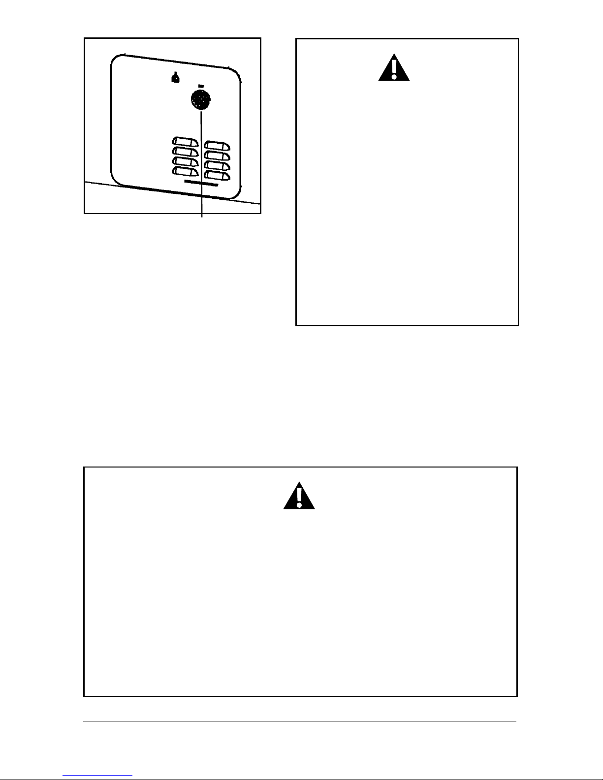
2. The exhaust tube extends beyond the door’s face through the clearance hole
BUT not beyond the face of the door. Be sure that the exhaust tube is seated
properly. See Figure 6
3. Ensure that the door lock operates smoothly and engages easily.
9Page
WARNING – FIRE AND/OR EXPLOSION
WARNING: These instructions must be followed exactly, or a re or explosion may result
causing property damage, personal injury or death.
DO NOT use matches, candles or other sources of ignition when checking for gas leaks.
WARNING! PRODUCT DAMAGE
• DO NOT FORCE THE DOOR CLOSED with the tube pressed inside the door.
Doing so may damage the door or the exhaust tube and mis-align the sail switch.
WARNING!
It is necessary to use only an applicable Girard Water Heater Door (part numbers:
1GWHD, 1GWHDA6, 1GWHDAS10) with a Girard GSWH-1M Water Heater. Use of any
other brand of water heater door will affect the operation and performance of the Girard
Water Heater and may cause a hazardous condition.
10Page
WARNING! CAUTION!
• Disconnect the unit from the gas supply
line during any pressure testing of the
gas system in excess of ½ PSIG
(3.4 kPa, 14” water column [W.C.]). DO
NOT set inlet pressure higher than the
maximum indicated on rating plate of gas
valve (13” W.C.).
• If an external electrical source is utilized,
the appliance, when installed, must be
electrically grounded in accordance with
local codes or, in the absence of local
codes, with the National Electrical Code,
ANSI/NFPA 70 and/or the CSA C22.1,
Canadian Electrical Code.
Figure 6
This completes the installation of the Model GSWH-1M water heater.
Insert exhaust tube
through door opening
CONSUMER SAFETY WARNING
• Use with LP gas only.
• Shut off gas appliances and pilot lights when refueling.
• Turn gas OFF at the LP tank when vehicle is in motion. This disables all gas
appliances and pilot lights. Gas appliances must never be operated while
vehicle is in motion.
• LP tanks must be lled by a qualied gas supplier only.
• Should overheating occur, turn gas OFF at the LP tank and turn the operating
switch to the OFF position.
OPERATING INSTRUCTIONS
Understanding How the Girard Tankless Water System Works
In a conventional installation the Girard Tankless Water Heater is connected to:
1. The RV’s cold water system deriving its water input from a pressurized (45 psi or greater)
source such as a shore connection or an RV water pump connected to the fresh water storage
tank.
2. The RV’s hot water system (i.e. faucets and shower)
3. The RV’s LP Gas system capable of supplying its rated BTU requirement.
The Girard Products model GSWH-1M is a new ‘induced-draft’, tankless water heater
designed specically for Recreation Vehicles (RV). Its conguration and size are consistent
with the tank based RV water heaters currently in use and is designed for OEM’s and after market use by the RV industry. A main feature of the GSWH-1M is a Gas Modulation Control
(GMC - see Figure 5), which is installed inside the vehicle. Using the GMC, the heating
capacity of the water heater can be manually adjusted from a minimum of 18,000 BTUs to a
maximum of 36,000 BTUs and the incoming water temperature will rise 20°- 70° (F) based
on the actual Hot water ow and the Gas Modulation Control (GMC) setting.
The Girard Tankless Water Heater heats water while it is being used i.e., on demand. The output
temperature of the water depends on the GMC setting, the inlet water temperature AND the Hot
water ow.
11Page
IMPORTANT!
• The presence of a ow restrictor in the hot water line may limit your ability
to reach a comfortable water temperature. For best results remove the
restrictor in the shower head.
• Purge air out of ALL hot and cold water lines, including outside shower, toilet
and wash machine water lines (if applicable).
“LIMITING” Emergency Cut Off (ECO)
If the water ow is low or reduced and the Gas Modulator Control (GMC) Dial is set
too high, “LIMITING” may occur which is: The Hot water temperature will exceed the
Emergency Cut-Off (ECO) setting of 131 degrees (F) and the burner will shut off. When
the Hot water outlet temperature drops to approximately 110 degrees (F) the burner
will reignite. The End User will experience the Water Heater cycling from Hot water then
Cooler water. To correct this “Limiting/cycling” the Gas Modulation Control (GMC) Dial
needs to be turned counter clockwise and/or increase the Hot Water ow.
IF “LIMITING” OCCURS, TURN THE GAS MODULATION CONTROL (GMC) DIAL
COUNTER CLOCKWISE AND/OR INCREASE THE HOT WATER FLOW.

12Page
F. User operation of the GSWH-1M
Since an RV’s environment and water source (temperature, flow/pressure) can
change on a daily basis and the Girard GSWH-1M Tankless Water Heater needs to
make “instant” Hot water based on these changes, Girard Products has designed
the Girard GSWH-1M Tankless Water Heater with multiple operation controls and
settings so the end user can achieve the desired Hot water temperature in nearly any
environment.
This is accomplished by: (a) adjusting the Gas Modulating Control Dial (GMC), (b) by
adjusting the Hot water flow and/or (c) by adding Cold Water to the Hot Water flow.
We suggest, before going on their first camping trip, the end user try the different
operating procedures (at every faucet) to acheive the desired Hot water temperature.
OPERATING PROCEDURES:
1. Purge the air out of all Cold and Hot Water Lines (don’t forget any outside faucets, toilet and
washer hook-ups). This only needs to be done on the rst time out camping (unless a water
line is depleted of water).
2. Open Water Heater Door and turn the Water Heater Power switch to the ON position. The
Power Switch can be left in the ON position for the entire camping season since it will only
draw power when there is a demand for Hot water.
3. Locate and set Gas Modulator Dial (GMC) to the appropriate setting (see g.5 on page 8).
a. Normal Weather – Set Dial to the middle area.
b. Extreme Cold Weather – Set Dial to the extreme right area (large ame).
c. Extreme Hot Weather – Set dial to the extreme left area (small ame).
4. Turn on the Hot water faucet to a normal ow rate (normal would be ½ to 2/3 ow rate). Wait
for the water to travel from the Water Heater to the faucet (this may be a few seconds to
nearly a minute, depending on the RVs plumbing conguration and location of the faucet and
the Water Heater).
5. If the Hot water is not Hot enough you may do the following:
a. Turn the Gas Modulating Dial “clockwise” to increase the ame/BTUs to raise the
Hot Water Temperature. NOTE: Use caution not to increase the Dial too much which
could cause the Hot Water temperature to rise to the point the Water Heater “limits”
and turns OFF the ame (ame shut off is approximately 131 degrees F).
b. Reduce the Hot water ow to increase the Hot water temperature
6. If the Hot Water is too Hot you may decrease the Hot water temperature by:
a. Turn the Gas Modulator Dial counter-clockwise to decrease the ame/BTUs.
b. Increasing the Hot Water ow.
c. Gradually add Cold water.
NOTE: Adding Cold water to may cause the Water Heater to “limit” if the Hot Water temperature
approaches the 131 degree (F) range which may happen if the Hot water flow decreases to
below 1 Gallon per Minute (GPM).
 Loading...