

Girard Products G-2000, G-1500 Owner's Manual
GIRARD SYSTEMS
RV AWNING PRODUCTS
G-2000 CASSETTE PATIO AWNING
G-1500 DOOR AWNING
OWNERS MANUAL
INSTALLATION, OPERATION, ADJUSTMENT AND REPAIR
Rev. 010112
1361 CALLE AVANZADO, SAN CLEMENTE, CA 92673 (949)259-4000 FAX (949)276-5500
TABLE OF CONTENTS
BASIC SYSTEM OVERVIEW PG. 6
IMPORTANT REMINDERS PG. 7
QUICK START PG. 8
INSTALLATION MANUAL
PRODUCT DESCRIPTION PG. 9
TOOLS REQUIRED PG. 9
UNPACKING PG. 11
LAYOUT, MOUNTING THE BRACKETS PG. 12-15
BRACKET PLACEMENT CHART PG. 14
MOUNTING THE AWNING TO THE BRACKETS PG. 16
INSTALLATION OF COUPLED AWNINGS PG. 17-21
WEATHERSTRIPPING INSTALLATION PG. 22
ANEMOMETER INSTALLATION PG. 23
MOTION SENSOR PG. 24
TESTING AND ADJUSTMENTS
ADJUSTING MOTOR LIMIT SW ITCHES PG. 25-26
ADJUSTING PITCH ARM HEIGHT PG. 27-28
TESTING THE ANEMOMETER PG. 29
ADJUSTING THE LEAD RAIL PG. 29
TROUBLESHOOTING GUIDE PG. 30-31
WARRANTY LABOR TIME GUIDELINES PG. 32
COMMON REPAIR PROCEDURES
MOTOR REPLACEMENT PG. 33-35
FABRIC REPLACEMENT PG. 36-38
ARM REPLACEMENT PG. 38-40
CARE AND MAINTENANCE GUIDE PG. 41-43
TECHNICAL DRAWINGS PG. 44-47
5 | Page
The top cover or fabric rolled onto the roller tube and connected to the lead
GC136
98GC230
Basic System Overview
Your G-2000 and G-1500 Awnings consist of three main components:
1.
Mechanical System
The enclosure (or cassette) protects the fabric while closed.
•
The roller tube which is mounted within the cassette.
•
•
– consisting of:
rail that extends from the enclosure when the awning is opened.
The folding arms that supports the lead rail and the fabric.
•
The tubular motor which is mounted inside of the roller tube that allows the awning to
•
extend and retract.
2.
Electronic controls
Anemometer (wind sensor) automatically retracts the awning in case of high wind that
•
– to power and operate the motor
may damage the awning system.
Motion Sensor – This can be used in place of the anemometer.
•
G-Links model GC136 Motor Control (single motor) to power and operate the motor.
•
DC motor control.
•
Wireless Motor – This motor does not require a motor control.
•
3.
User Controls
– for awning operation
6 | Page
Important Reminders
Before using your awning make sure that all of your electrical circuits are operating correctly.
Recreational Vehicles can generate AC power from three separate sources; shore power
(hookup), generator, or inverter. The electrical system transfer switch in your vehicle will select
power for the awning as follows:
Shore Power
–
if connected;
Generator Power
–
if generator is running;
Inverter Power
–
batteries must be charged for inverter operation.
Your
G-2000
is usually operated using a 110Volt AC motor. However, some awnings are
equipped with 12Volt DC motors. Your
However, some awnings are equipped with a 110 Volt AC motor.
For a detailed description and user instructions for all
electronic and user controls please refer to the Girard Link
System (G-Link) manual supplied with the awning. If you
do not have a copy of the G-Link manual you may
download a copy from the Girard Systems website at
www.girardrv.com.
G-1500
is usually operated using a 12 Volt DC motor.
NOTICE
7 | Page
Extending/Retra cting Awning
1.
Programming the Remote Control
Wireless remote controls must first be programmed to your awning. Programming is usually
done at the factory and the user does not need to program his units.
2.
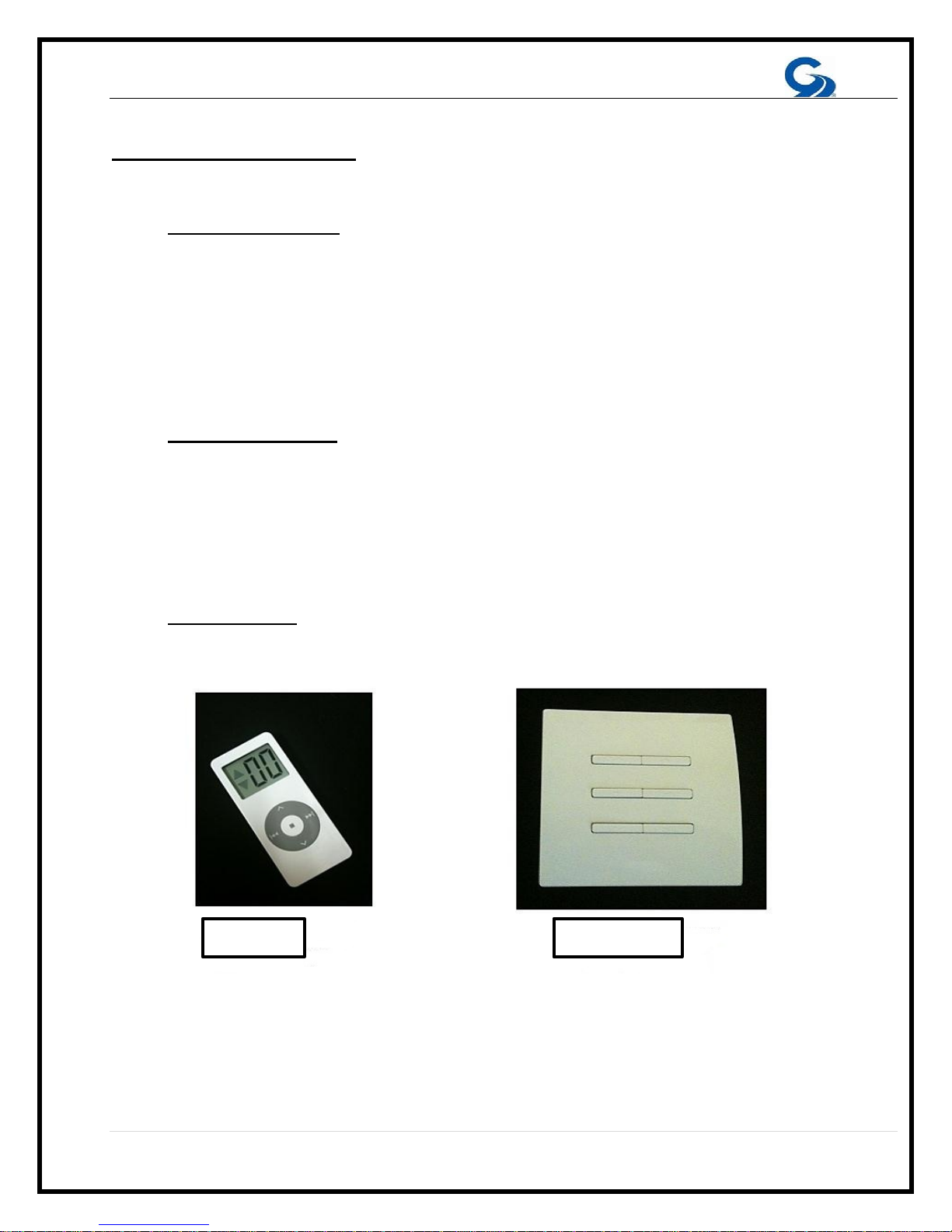
Using the Remote Controls
G-Links
different communication channel for each awning. If your unit can control only two channels it
will indicate the channel selected using one of two LEDs above the control buttons. If your unit
can operate more than two channels an LCD display shows the number of the channel that is
currently selected. Your remote control will have the capability to control every Girard System
product installed on your coach up to a maximum of 15 units.
hand held Remote Controls are capable of controlling several awnings and use a
• To operate the hand held Remote Control you only need to press the button labeled
with the appropriate icon shown on the round rocker switch below the channels display.
• Channel selection is made by pressing the two icons marked on the round rocker switch
below the display.
• Pressing the center button will stop the motor.
• The custom LCD display, when activated by pressing any of the above buttons, shows
the active channel and the direction of motion.
• The operation of wall mounted switches is self-explanatory and normally UP indicates the
RETRACT function and DOWN the EXTEND function.
8 | Page

awnings controls’ use a RF (radio frequency) link to communicate
INSTALLATION MANUAL
Product Description
The G-2000 and G-1500 awning systems provide protection from the sun at a touch of a
button. The G-2000 and G-1500 awnings are built to your specifications with the highest
quality materials available, your units features:
• A standard motor that operates with a wireless motor control, or a wireless motor
that operates with an integrated motor control.
• An anemometer (wind sensor) or a Motion Sensor that will retract the awning to
prevent damage from the wind.
• A hand held Remote Control
• A wall mounted Remote Switch
• Options include; electronic automation controls to ensure proper closing at all
times, a control to retract all awnings when the vehicles’ motor is started, and
more….
Your G-2000 and G-1500
with each other. This simplifies the installation and maintenance by removing the need for
extensive wiring. This RF network is called the G-Link system. For more information please
refer to the G-Link manual that was included with your awning. All necessary power cables are
supplied with this product.
Getting Started
Tools required:
Electric Drill
•
Tape measure
•
(2) ladders
•
Socket wrench: 7/16” deep socket
•
Chalk line
•
Flat head screwdriver (small)
•
Phillips screwdriver
•
Caulking gun
•
(2) tubes silicone caulking
•
Drill bits: 1/8”, 3/8”, and 7/16”
•
Allen wrenches: 5mm and 4mm
•
Open-end wrenches: 10mm, 19mm
•
Keyhole saw
•
9 | Page
WARNING
ALL ELECTRICAL WORK MUST CONFORM TO APPLICABLE
ELECTRICAL CODES AND STANDARDS.
• Turn off power before beginning any electrical work.
• Please consult your RV’s wiring diagram to locate any wiring
prior to any drilling or any installation procedures.
• Ensure that placement of controls, cables, and wires are not
in any way obstructed. This can damage the compon ents an d
obstruct electrical current.
• Use only certified components.
Duration:
Prior to beginning installation sequence
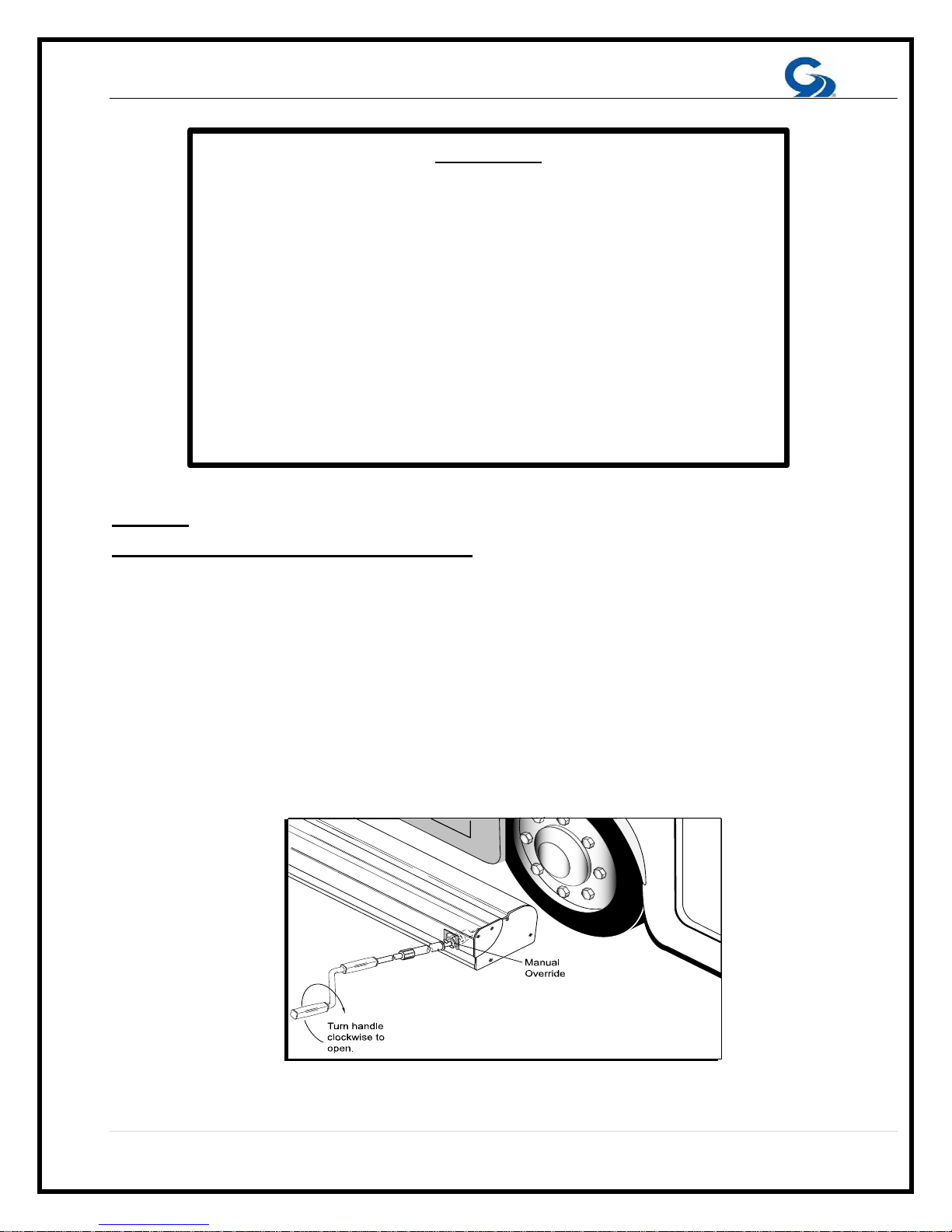
1. Insert end of crank into manual override receiver, located at extreme end of aw ni ng .
2. Push in and rotate handle 1/4-turn clockwise. Let handle drop approximately 1/2”. (Handle
should lodge in receiver and awning may now be extended/opened.)
3. Extend awning approximately 12” by turning handle clockwise (see Fig. 1); confirm that
awning shoulders are in proper locations; make note of shoulder locations; and retract/close
awning by turning handle counter-clockwise.
NOTE: Roof mount awnings will have the manual override receiver positioned on the
top of the awning.
4.5 hours (based on two installers)
:
(FIGURE 1)
10 | Page
FOR PERSONAL SAFETY AND QUALITY OF INSTALLATION, TWO
INSTALLERS ARE RECOMMENDED FOR THIS PRODUCT
A. UNPACKING
1. Before starting any of the installation procedures unpack the awning and inspect the
product for any possibl e damage t ha t may have occurred during shipping.
2. Before starting any of the installation procedures review the length and motor
placement of your awning for correctness.
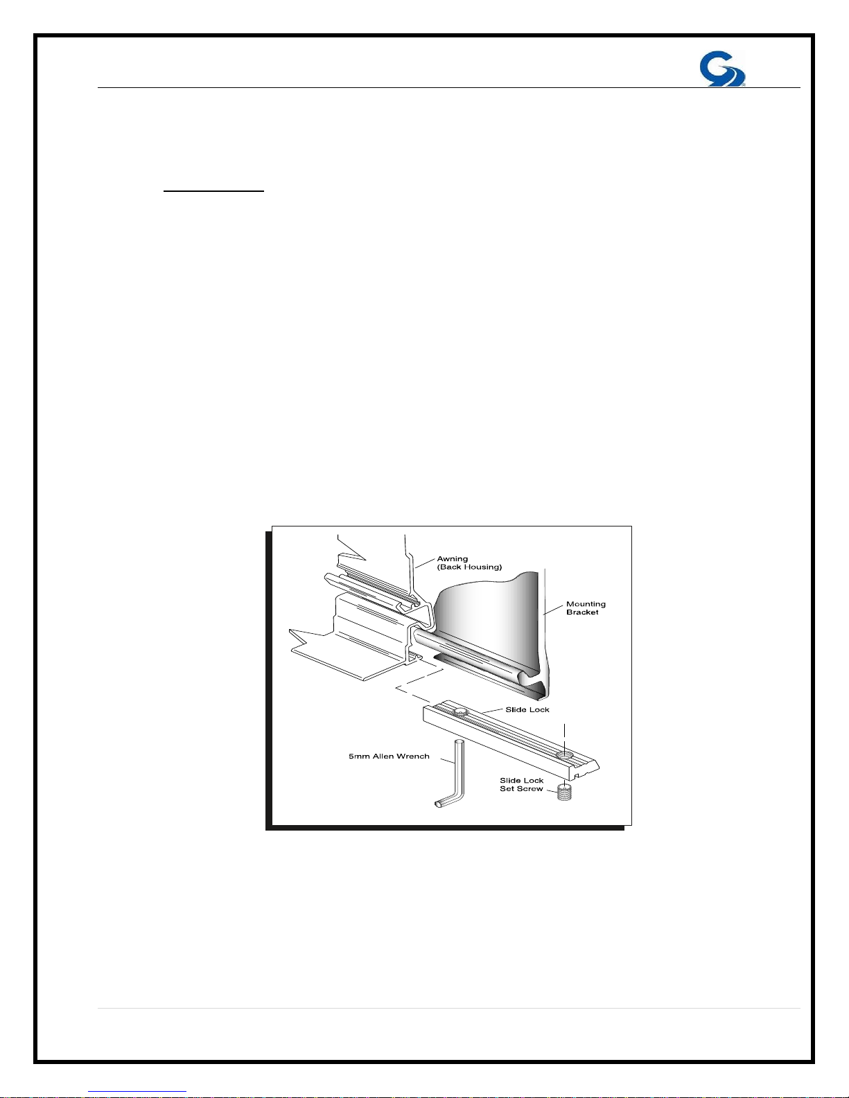
3. When you have determined that the product is to your satisfaction, remove the
mounting brackets and place the awning in a safe location while preparing the RV.
A. To remove the brackets locate the slide lock that retains the bracket to the
housing. (Figure. 2)
B. Using a 5mm Allen wrench loosen the set screws on the slide locks.
C. Once the set screws have been loosened the slide locks should slide freely,
clear the slide lock away from the bracket.
D. You should now be able to remove the bracket.
4. If you have discovered any damage or missing parts please follow the instructions in
the Warranty section of this man ual.
(FIGURE 2)
11 | Page
B. LAYOUT, MOUNTING THE BRACKETS
ROOFMOUNT APPLICATION –The clearance needed for the roof mount application of
the G-2000 varies by manufacturer. The shape of the roof, the depth of installation, type
of roof mount bracket used and all other factors should be taken into consideration
when installing this product. It is up to the installer to find adequate s tructure to fasten
the roof mount brackets. All caution must be taken to weather seal all installation
perforations. Please consult Girard Systems if there are any questions regarding your
installation.
12 | Page

NOTE: Please consult your RV’s wiring diagram to ensure that no wiring will be
damaged while drilling the hole.
A. SIDEWALL APPLICATION
NOTE: Please take into consideration all possible clearances, and obstacles before
installing this awning. Items such as slide rooms, etc. vary from one manufa cturer to
another. Please consult Girard Systems if there are any questions regarding your
installation.
1. The mounting brackets and hardware used for this application are included with
your awning.
2. Determine the location for the final installation position of the awning, including
height to be installed.
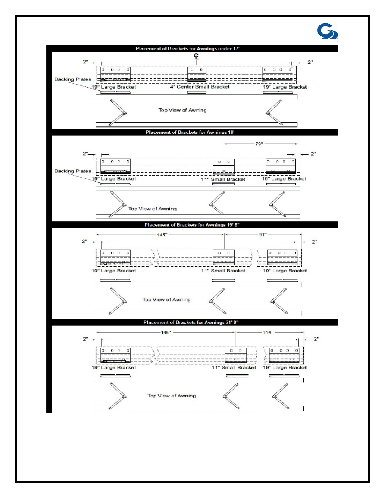
3. Mounting brackets must be installed within two (2) inches of the ends of the
awning. Once you have determined the location of the two end brackets snap a
chalk line between the two points to ensure straightness of the installation. You
will be able to use this reference line to install the smaller center bracket at a
later time.
4. To find the location of the smaller center bracket please refer to chart on the
following page. NOTE: The location of the center bracket must fall directly
centered behind the center shoulder location. Failure to follow these
instructions will void the warranty of this product.
5. Now that you have located the bracket locations, using the bracket as your
template, mark the holes for fastening the bracket.
6. Using a 1/8” bit (8” long), pilot drill the centers of the marked holes. Inside of the
RV verify the locations of the backing plates. NOTE: Please consult your RV’s
wiring diagram to ensure that no wiring will be da maged while drilling the
hole.
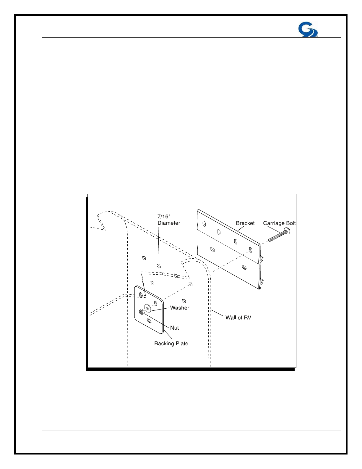
7. Pre-drill six 7/16” holes per mounting bracket through the pilot holes.
8. Apply a liberal amount of silicone caulking around each hole before installing the
brackets.
9. Install the two (2) outer brackets, and then the center bracket (if required) with six
7/16” carriage bolts, washers, nylon nuts and two(2) backing plates per bracket.
(Figure 3) Tighten bolts and then apply silicone caulking to the top edge and both
sides of each bracket.
10. On the motor side of the awning drill a 7/16” hole for the awning motor cable to
enter the RV near the electrical source. Position the hole 1” to the left or right of
the bracket depending on motor location. Do not drill hole higher or lower than
the bracket. This will ensure that it will not be seen after the awning is installed.
13 | Page
14 | Page
If you are using a 12V Motion Sensor locate the wire, then drill the
11. On the motor side of the awning drill a 7/16” hole for the awning motor cable to
enter the RV near the electrical source. Position the hole 1” to the left or right of
the bracket depending on the location of the motor. Do not drill hole higher or
lower than the bracket. This will ensure it will not be seen after the awning is
installed.
12.
appropriate sized hole to rout the wire to your interior 12V source. Make sure to
seal any perforations made in the shell of the vehicle.
13. Locate the white wire grommet supplied with the awning. Place a fine bead of
silicone around the body of the grommet. Slide grommet into the 7/16” hole
previously drilled for the motor wire.
(FIGURE 3)
15 | Page
B. MOUNTING THE AWNING TO THE BRACKETS
1. Lift the awning into position for installing the awning on the brackets.
A. Ladders are usually sufficient; however, a scaffold or forklift may be used.
B. If using a forklift use all necessary caution to protect the surface of the
awning. Lift from the center of the awning to maintain product balance while
elevating.
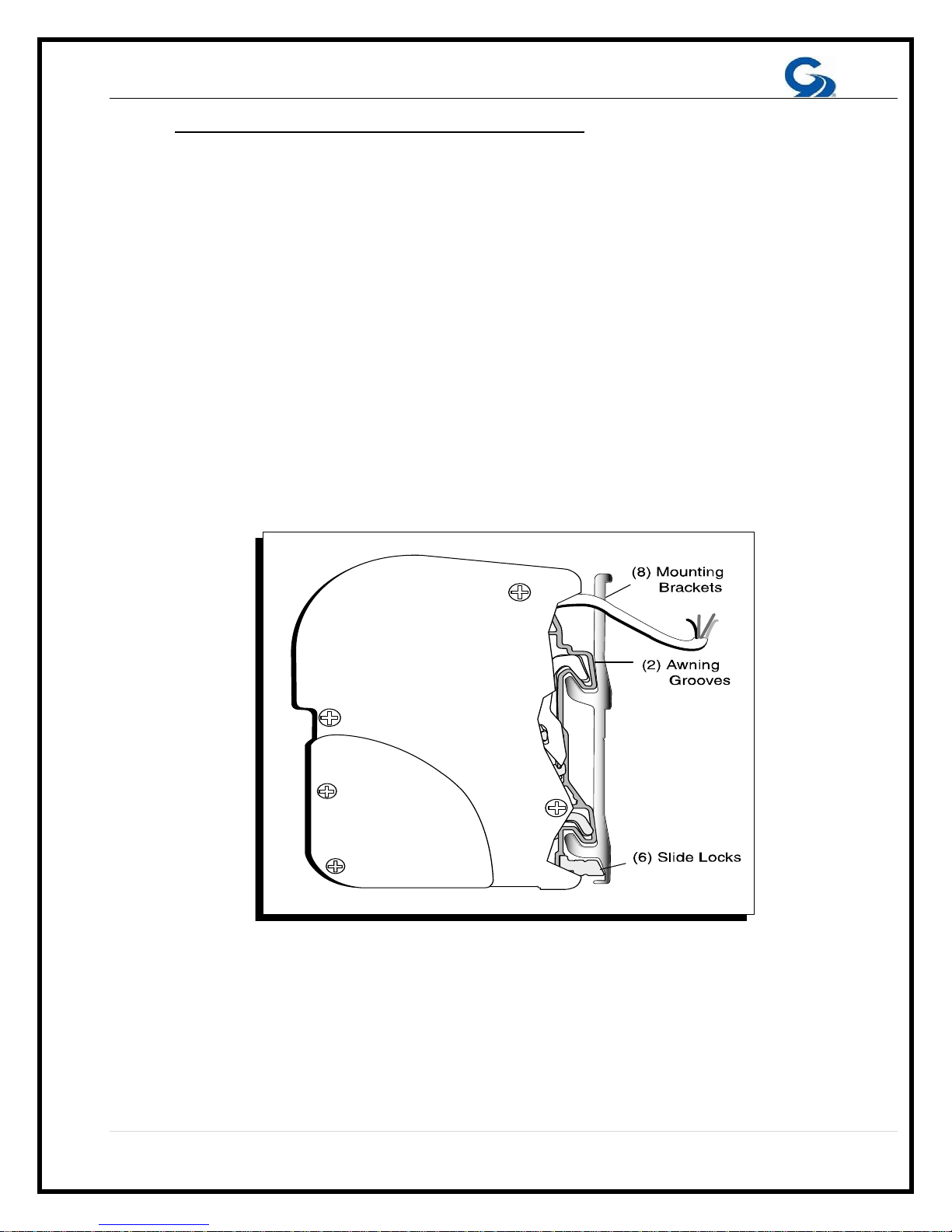
2. Place the awning onto the brackets (Fig. 4 #8) while feeding the motor wire through
the white motor grommet. A small amount of lubricant may aid the feeding of the
wire. Make sure the grooves (Fig. 4 #2) of the awning are securely engaged into
the channels on the bracket. (Figure 4)
3. Secure the awning by moving the slide locks (Fig. 4 #6) along the bottom awning
track until they are located under their respective brackets. The final position of the
slide lock should be directly under the shoulder of the arm.
4. Once the final location of the slide locks has been achieved, tighten both set
screws on each slide lock with a 5mm allen wrench.
(FIGURE 4)
16 | Page
C.
INSTALLATION INSTRUCTIONS FOR COUPLED AWNINGS
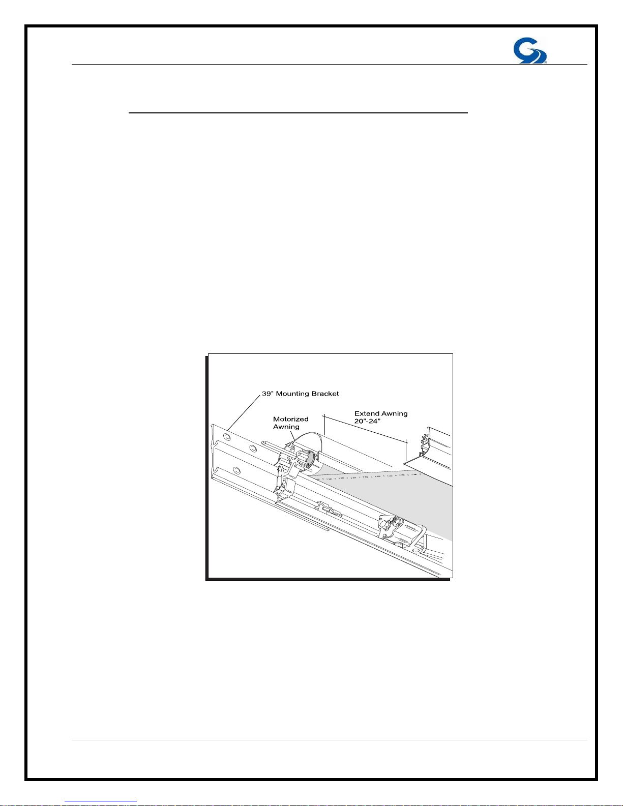
1. The 19” end brackets are installed 2” from the overall length of the awning. The
39” mounting bracket is located in the center, at the junction of the two awnings.
Additional brackets need to be located behind, and centered on the arms of each
awning.
2. After all the mounting brackets are firmly attached; place the motorized awning on
the mounting brackets. Place the slide locks under each plate, but do not tighten.
A fourth slide lock should be on the awning. This lock will be placed between the
two awnings once they are mounted. (Refer to Figure 16 in the Installation
Manual.)
3. Extend the motorized awning 20”–24”. Temporarily install the controller to the
motor and use the remote control.
(FIGURE 5)
NOTE: Do not remove the plastic from the non-motorized awning.
from the area in contact with the mounting bracket.
Move the plastic away
17 | Page
 Loading...