

GB
Gira nurse call system Plus
Short instructions
Ward control centre Plus 5971 00
Gira
Giersiepen GmbH & Co. KG
Electrical Installation
Systems
P.O. Box 1220
42461 Radevormwald
Phone +49 (0) 2195 / 602 - 0
Fax +49 (0) 2195 / 602 - 191
www.gira.com
info@gira.com
4992 62 34/11
Safety instructions
Installation and mounting of electrical devices may only be carried out by qualified electricians.
Failure to observe the instructions can result in damage to the
device, fire or other dangers.
Isolate before working on the device or load. Take account of all
circuit breakers supplying dangerous voltage to the device or
load.
Always connect protective conductors, see in fig. 1!
i
Note: comply to DIN VDE 0834.
Observe the content of DIN VDE 0834 and any other applicable regulations.
Function
The ward control centre Plus of the Gira nurse call system Plus
controls and regulates the devices connected to the ward bus,
such as room terminals with and without speech module. The
device may be connected to the system central control unit via
the system bus (nurse call system Plus LAN, and "large system"
setting in the configuration assistant).
The Gira nurse call system Plus can also be controlled and regulated from only a single ward control centre Plus without a system
central control unit ("small system" setting in the configuration
assistant).
All devices existing in the system are automatically recognised.
Devices can be integrated or removed from the call system at a
later time.
The ward control centre Plus is immediately ready to use. Additional settings can be carried out via the configuration assistant in
the device.
i
Note: read the system operating instructions.
Become familiar with all the possibilities of the device and the
complete call system. Please read the system operating instruc-
tions
and use the onscreen help information in the configuration
assistant. You can find the system operating instructions in further
language variations on the CD-ROM.
Scope of supply
• Ward control centre with configuration software.
• Jumper for activating terminating resistances on the ward
bus.
• Connection plug for ward bus and power supply.
• System operating instructions in German and system overview plan (printed) and further languages as PDF files on enclosed CD-ROM.
Installation
The ward control centre Plus must be installed in a dry, dust-free
and well ventilated location.
Installation is intended on a DIN top-hat rail.
Important! Danger of overheating!
With an unfavourable installation location, heat accumulation
may cause device overheating. This may cause damage. Ensure
sufficient air circulation to prevent heat accumulation.
Important! Do not install in patient's rooms!
The device must be securely installed.
Access to the device for skilled personnel must be possible at all
times.
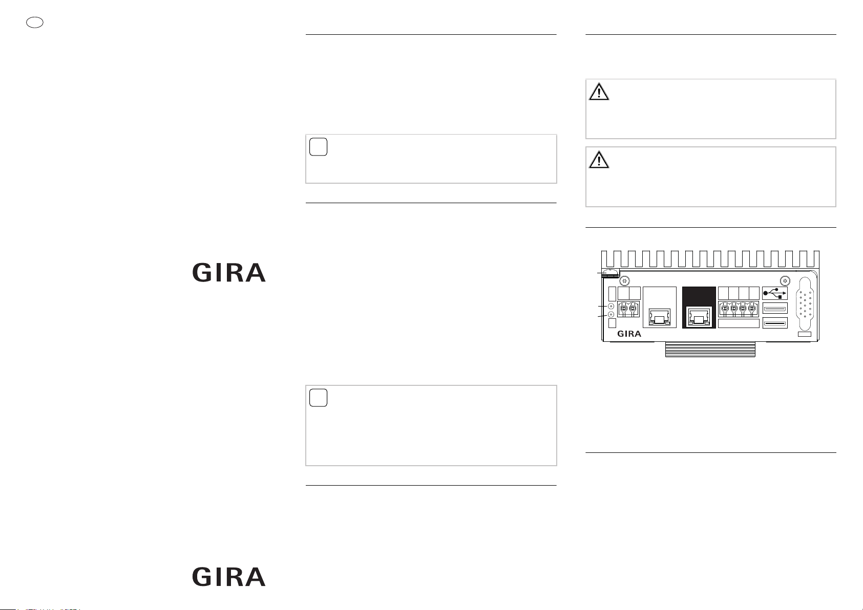
Connections
The ward control centre Plus has the following connections:
Extern
GND
+24V
Power
LAN
834 Plus
LAN
S-Bus+
S-Bus-
A-Bus+
A-Bus-
Bus
Legend:
Earthed connection
Green LED Power on
Yellow LED Bus active
+24 V/GND DC power supply
Fig. 1: Ward control centre connections
Station
Bus
VGA
External LAN RJ45
Nurse call system
Plus LAN RJ45
Ward bus
2 x USB
VGA pin jack
Requirements for start-up
The requirement for operating the ward control centre Plus is a
connection to the power supply and to the ward bus or system
bus.
- Room bus, ward bus and system bus (with "large system" setting) are installed and ready for operation.
- The ward control centre is the first device on the ward bus.
With the last device on the bus, the terminating resistances
must be activated with the enclosed jumper.
- External power supply (Order No.: 5999 00, with UPS or Order
Nos.: 5998 00/5981 00) is installed and ready for operation.
Use the enclosed device plug for connecting.
- Start-up PC with internet browser, LAN connection and network cable (patch or crossover) are available.
Start-up
1. Connect the power supply to the ward control centre.
Important! Voltage on the ward control centre!
The ward control centre Plus does not have a mains switch. The
ward control centre Plus boots immediately after connection
with the external power supply. This procedure takes up to
60 seconds.
2. Connect your start-up PC to the "External LAN" connection
via the network cable.
i
Note: IP address range of the start-up PC.
Ensure that the IP address of your start-up PC is between
192.168.0.1 and 192.168.0.254 (but not 192.168.0.111) (subnet
mask: 255.255.255.0). Please consult the "Ethernet basics"
chapter of the system operating instructions for further details of
this.
3. Start the internet browser on your start-up PC. Enter the
IP address 192.168.0.111 into the address bar of the internet
browser.
The start screen of the configuration assistant opens.
i
Note: the ward control centres are pre-configured.
Each ward control centre is pre-configured for operation in a
large system (with a system central control unit).
In this case do not specify any further settings in the configuration assistant of the system central control unit.
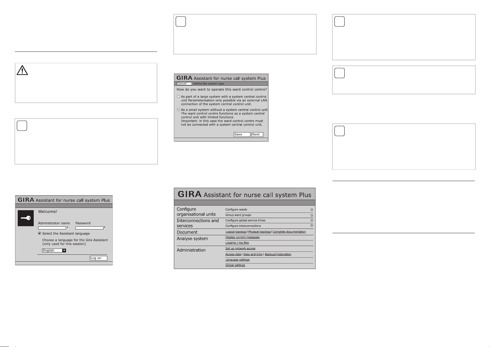
Proceed as follows if the device is to be operated in a small system (with only this ward control centre):
.
Fig. 3: Defining the system type
1. Select "small system" option.
2. You can save your selection that deviates from the standard
configuration via "Save".
3. Click on "Next".
The overview screen of the configuration assistant opens.
i
Note: read the system operating instructions.
Become familiar with all the possibilities of the device and the
complete call system. Please read the system operating instruc-
tions
and use the onscreen help information in the configuration
assistant. You can find the system operating instructions in further
language variations on the CD-ROM.
Note: connect the nurse call system Plus to an existing
i
network.
Consult a responsible network administrator before carrying out
network settings.
To connect the ward control centre to an existing (hospital) network, the "External LAN" connection can be configured in the
configuration assistant via the menu item Administration / Set
up network access (in fig. 4 ()).
i
Note: using a time server.
If the ward control centre Plus is not connected to an external
network (e.g. company or hospital network) via the "external
LAN" connection, then the system time of the nurse call system
Plus cannot be automatically sourced via a time server (NTP
server) on the internet.
Warranty
The warranty is provided in accordance with statutory requirements via the specialist trade.
Please submit or send faulty devices postage paid together with
an error description to your responsible salesperson (specialist
trade/installation company/electrical specialist trade).
They will forward the devices to the Gira Service Center.
Fig. 2: Start screen of the ward control centre
1. Select the language you require for starting the configuration
assistant.
2. Enter "admin" in the administrator name field and "admin" in
the password field.
3. Click on "Log on".
Decide which system type you wish to operate.
Fig. 4: Overview screen in the configuration assistant
You can now carry out settings to the system. Please read the sys-
tem operating instructions and use the onscreen help in the configuration assistant for details.
Technical data
Operating voltage: 24 V DC
Current consumption: 300 mA
Ambient temperature: -5 °C to +50 °C
Storage temperature: -25 °C to +75 °C
Humidity: max. 90 %
Protection type: IP 20
Connection terminals: Ø to 2.5 mm
Mounting: intended for DIN top-hat rail
2
 Loading...