


TeleCoppler 2
Operating Instructions
2 Overview
Overview
Scope of Delivery
TeleCoppler 2 analog 2335 00
with
operating instructions
quick guide to initial operation
CD-ROM with PC software
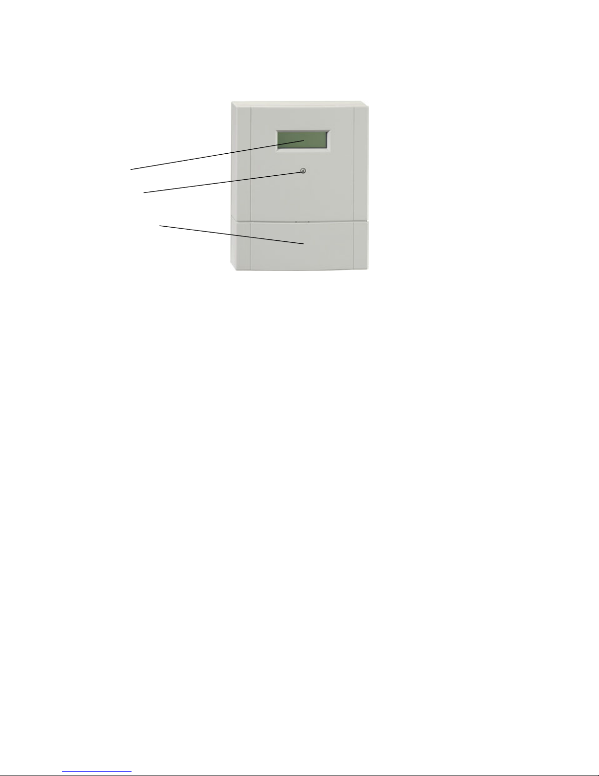
Display
Turnkey
Terminal
screw cover
Accessories (optional)
Receiver set for TeleCoppler 2 0907000
All given announcements of the TeleCoppler 2
can be individually recorded with the handset.

Table of Contents 3
Table of Contents
1 General Function
2 Functional Principle with the Analog Network . . .6
3 Installation
3.1 Wall Mounting . . . . . . . . . . . . . . . . . . . . . . . . . . . .7
3.2 Connections
3.2.1 Connection of Power Supply . . . . . . . . . . . . . . . . . .8
3.2.2 Assignment of the Inputs . . . . . . . . . . . . . . . . . . . . .9
3.2.3 Connection to the Analog Network . . . . . . . . . . . . .10
3.2.4 Connection to External Alarm Confirmation
Push-Button . . . . . . . . . . . . . . . . . . . . . . . . . . . . .11
3.2.5 Transparent Switching . . . . . . . . . . . . . . . . . . . . .11
3.2.6 Switching Output Assignment . . . . . . . . . . . . . . . .12
3.2.7 Operation with Current-Impulse Switches . . . . . . . .13
3.3 Initial Operation . . . . . . . . . . . . . . . . . . . . . . . . . .14
4 Settings
4.1 Operating Element . . . . . . . . . . . . . . . . . . . . . . . .15
4.2 Display . . . . . . . . . . . . . . . . . . . . . . . . . . . . . . . .15
4.3 Default Settings . . . . . . . . . . . . . . . . . . . . . . . . . .15
5 Display Menu Guide
5.1 Initial Settings . . . . . . . . . . . . . . . . . . . . . . . . . . . .17
5.1.1 Provider for Analog Telephone Mode . . . . . . . . . . .18
5.1.2 Telephone Options for Analog Mode . . . . . . . . . . .19
5.1.3 Set Time/Date . . . . . . . . . . . . . . . . . . . . . . . . . . .20
5.2 Edit Announcements . . . . . . . . . . . . . . . . . . . . . .21
5.3 Configurate Alarm Inputs . . . . . . . . . . . . . . . . . . . .22
5.4 Set Switching Outputs . . . . . . . . . . . . . . . . . . . . .23
5.5 Display Alarm Memories . . . . . . . . . . . . . . . . . . . .24
5.6 Summary of Menu Items . . . . . . . . . . . . . . . . . . . .25
6 Configuration
6.1 Configuration by Turnkey . . . . . . . . . . . . . . . . . . . .27
6.1.1 Initial Settings Menu
6.1.1.1 Set Number of Dial Attempts . . . . . . . . . . . . . . . . .27
6.1.1.2 Set Code Number . . . . . . . . . . . . . . . . . . . . . . . .27
6.1.1.3 Set CLIP Numbers . . . . . . . . . . . . . . . . . . . . . . . .28
6.1.1.4 Set Number of Ringing Signals . . . . . . . . . . . . . . .29
6.1.1.5 Select Provider . . . . . . . . . . . . . . . . . . . . . . . . . . .29
6.1.1.6 Set Telephone Options . . . . . . . . . . . . . . . . . . . . .29
6.1.2 Announcements Menu
6.1.2.1 Select Display Language . . . . . . . . . . . . . . . . . . .31
6.1.2.2 Answering Machine Mode . . . . . . . . . . . . . . . . . . .31
6.1.2.3 Call up Announcements . . . . . . . . . . . . . . . . . . . .31
6.1.2.4 Edit Input Messages . . . . . . . . . . . . . . . . . . . . . . .32
6.1.2.5 Edit Alarm Messages . . . . . . . . . . . . . . . . . . . . . .32
6.1.2.6 Edit Message Texts . . . . . . . . . . . . . . . . . . . . . . .32
6.1.3 Alarm Inputs Menu . . . . . . . . . . . . . . . . . . . . . . . .33
6.1.4 PC Programming Menu . . . . . . . . . . . . . . . . . . . . .34
6.1.5 Switching Outputs Menu . . . . . . . . . . . . . . . . . . . .34
6.1.6 Alarm Messages Menu . . . . . . . . . . . . . . . . . . . . .35
6.2 Configuration by PC
6.2.1 General . . . . . . . . . . . . . . . . . . . . . . . . . . . . . . . .36

4 Table of Contents
6.2.2 System Requirements for the PC Program . . . . . . .36
6.2.3 Screen Description . . . . . . . . . . . . . . . . . . . . . . . .37
6.2.4 Initial settings . . . . . . . . . . . . . . . . . . . . . . . . . . . .38
6.2.5 Telephone Line . . . . . . . . . . . . . . . . . . . . . . . . . . .39
6.2.6 Switching Outputs . . . . . . . . . . . . . . . . . . . . . . . .40
6.2.7 Inputs . . . . . . . . . . . . . . . . . . . . . . . . . . . . . . . . .41
6.2.8 TeleCoppler 2 Configuration . . . . . . . . . . . . . . . . . .42
6.2.9 Alarm Memory . . . . . . . . . . . . . . . . . . . . . . . . . . .43
7 Function of the TeleCoppler 2 . . . . . . . . . . . . . .44
7.1 Switch and Control Devices . . . . . . . . . . . . . . . . .44
7.2 Correct a Wrong Code Number . . . . . . . . . . . . . . .45
7.3 Send Messages . . . . . . . . . . . . . . . . . . . . . . . . . .46
7.4 Confirm Alarm . . . . . . . . . . . . . . . . . . . . . . . . . . .48
7.5 Answering Machine Mode (AW Mode) . . . . . . . . . .49
7.6 Dial Tone Recognition . . . . . . . . . . . . . . . . . . . . . .50
7.7 Line Control . . . . . . . . . . . . . . . . . . . . . . . . . . . . .50
7.8 Behavior in Case of Power Failure . . . . . . . . . . . . .50
8 Hints on Operation
8.1 Summary of the Functions and Function Numbers . .51
8.2 Summary of the given Announcement Texts . . . . . .51
9 Troubleshooting . . . . . . . . . . . . . . . . . . . . . . . . .52
10 Technical Data . . . . . . . . . . . . . . . . . . . . . . . . . .53
11 Explanations to the Product . . . . . . . . . . . . . . .55
11.1 Warranty . . . . . . . . . . . . . . . . . . . . . . . . . . . . . . .55
11.2 Service . . . . . . . . . . . . . . . . . . . . . . . . . . . . . . . .55
11.3 Important information regarding rules for disposal of
electronic waste . . . . . . . . . . . . . . . . . . . . . . . . . .55

1 General Function 5
1 General Function
The TeleCoppler 2 is an alarming and remote switching device by which up to 6 conventional devices can be
switched via telephone. All
settings will be saved in case
of a power failure – except
for time and date. The behavior of the exits in case of a
power failure can be set (after
return of the power voltage:
ON, OFF or restoring the
switching state before the
power failure).
Conventional relays or currentimpulse switches can be connected to the switching outputs.
Furthermore, the TeleCoppler
2 is sending messages to selected participants (cf. phone
numbers). These messages
are activated by up to 6 contacts (sensors) which are connected to the alarm inputs (N1
to N6). At each of the inputs
break or make contacts can
be installed.
Should given messages –
send off by the alarm inputs
M1 to M6 – not be confirmed,
then a local alarm exit will be
switched.
The controlling will either be
performed with a DTMF telephone (DTMF = Dual-tone
multi-frequency) or with a
DTMF pocket dialer (optional).
In case of an answering machine being used at an analog
connection (AB mode), either
the answering machine or the
TeleCoppler 2 can be addressed.
Individual user data are easy
to program.
The TeleCoppler 2 is operated
by turnkey. Operation is supported by plain texts on a 20
character 4 line alphanumeric
LCD field and also by announcements (see page 51).
The user can choose among
6 display languages for the
messages.
The respective software is enclosed in the scope of delivery and supports comfortable
configuration. The PC must
have a serial interface.
Messages are transferred exactly to the selected participants by announcements,
SMS, e-mail, or fax. The number of dial attempts (0 to 12)
can be set.
The announcements can be
individually recorded by the
user. In order to do this, the
handset (optional) with the 4way RJ10 connector has to
be inserted in the socket (see
figure on page 9). The examples shown in chapter ”Function” will explain the operation.
6 2 Functional Principle with the Analog Network
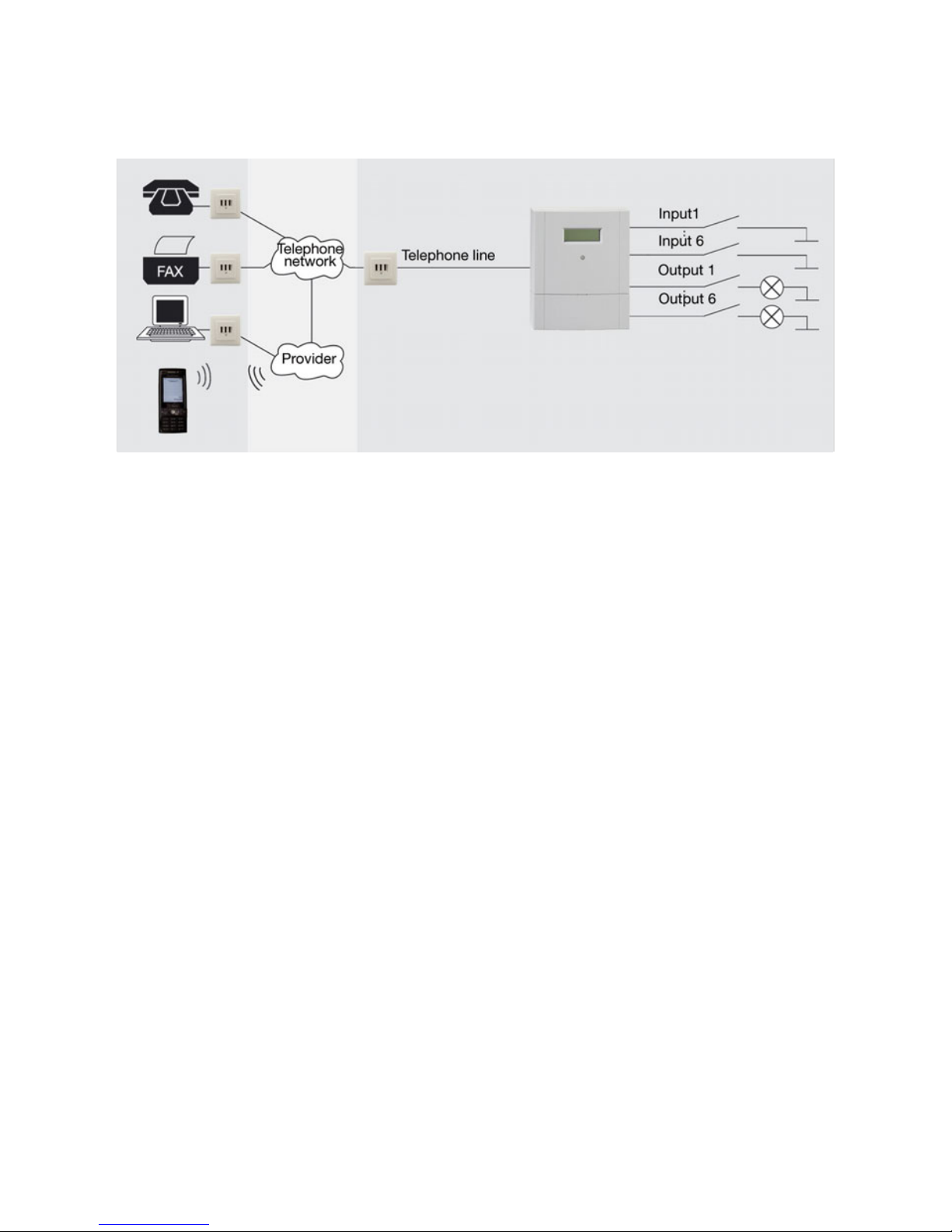
The above scheme shows the
use of the TeleCoppler 2 with
the analog telephone network.
Alarm messages are transmitted via telephone line to the
telephone network and from
there, according to message
type, forwarded as announcement or fax. There are only
the usual phone costs with
the network provider. e-mail
and SMS are transmitted by a
pre-selected provider. Costs
will depend on the provider’s
rates.
2 Functional Principle with the Analog Network
3 Installation
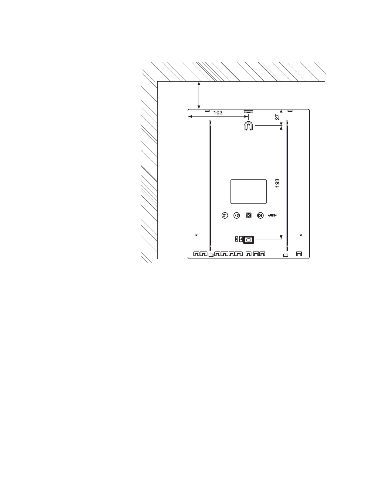
3.1 Wall Mounting
The TeleCoppler 2 must be installed in dry areas with ambient temperatures between -5
°C and +45 °C. For mounting
the TeleCoppler 2 analog there
should be a telephone wall
socket near-by.
The TeleCoppler 2 will be delivered with two dowels and
two screws. Easy wall mounting is, therefore, possible.
1 Mark the drill holes perpen-
dicular adjusted at a distance of 193 mm.
2 Drill two holes (6 mm diam-
eter) and insert the dowels.
3 Tighten the upper screw
until its screwhead sticks
out about 5 mm.
4 Hang the TeleCoppler 2 with
the upper mounting support
onto the screw.
5 Pull down the terminal
screw cover.
6 Tighten the lower screw in
the terminal screw area.
3 mm distance min.
3 Installation 7
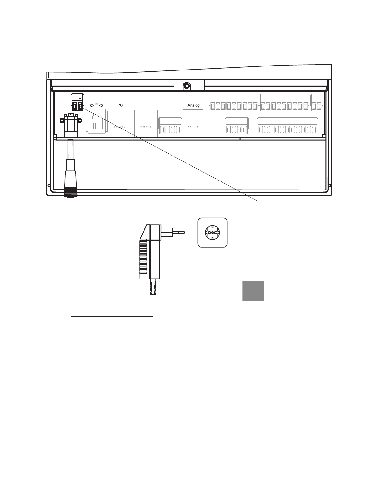
3.2.1 Connection of Power Supply
1
In case of an alternative
power supply (12 V DC) of
the TeleCoppler 2 by scew
terminals the plug power
supply must not be inserted.
Alternative connection to power supply
by screw terminals (e. g. using an uninterruptible power supply)
1
3.2 Connections
8 3 Installation
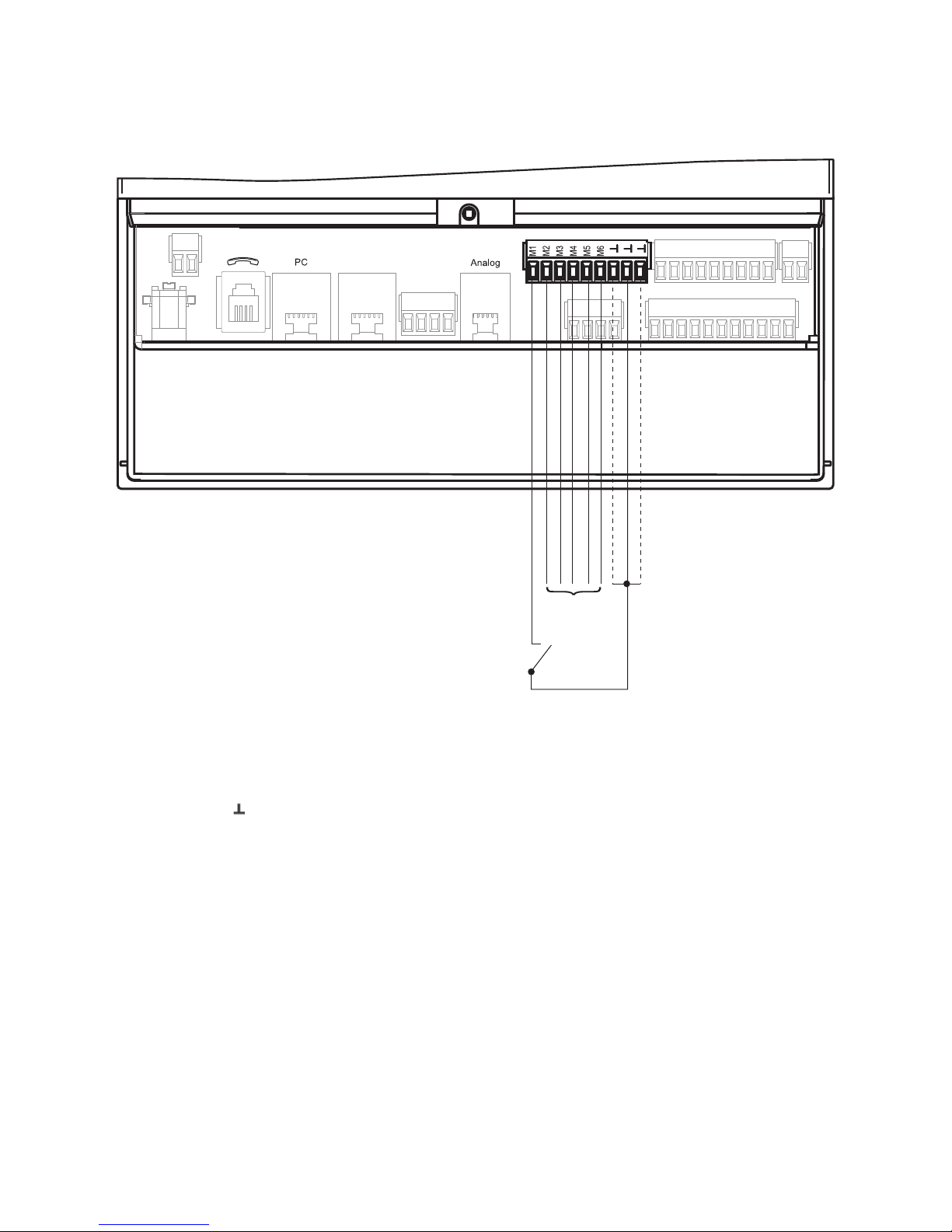
3.2.2 Assignment of the Inputs
potentialfree con-
tacts for
alarm inputs
as M1
Between the connecting terminals M1 and (mass potential) the desired switching
contact is being connected.
The voltage of the alarm input
M1 in idle mode is 3.3 V. If
the input is configurated as
make contact, the desired action will be performed by the
TeleCoppler 2 when making
the contact. If the input is
configurated as break contact,
the desired action will be
performed by the TeleCoppler
2 when breaking the contact.
3.2 Connections
3 Installation 9
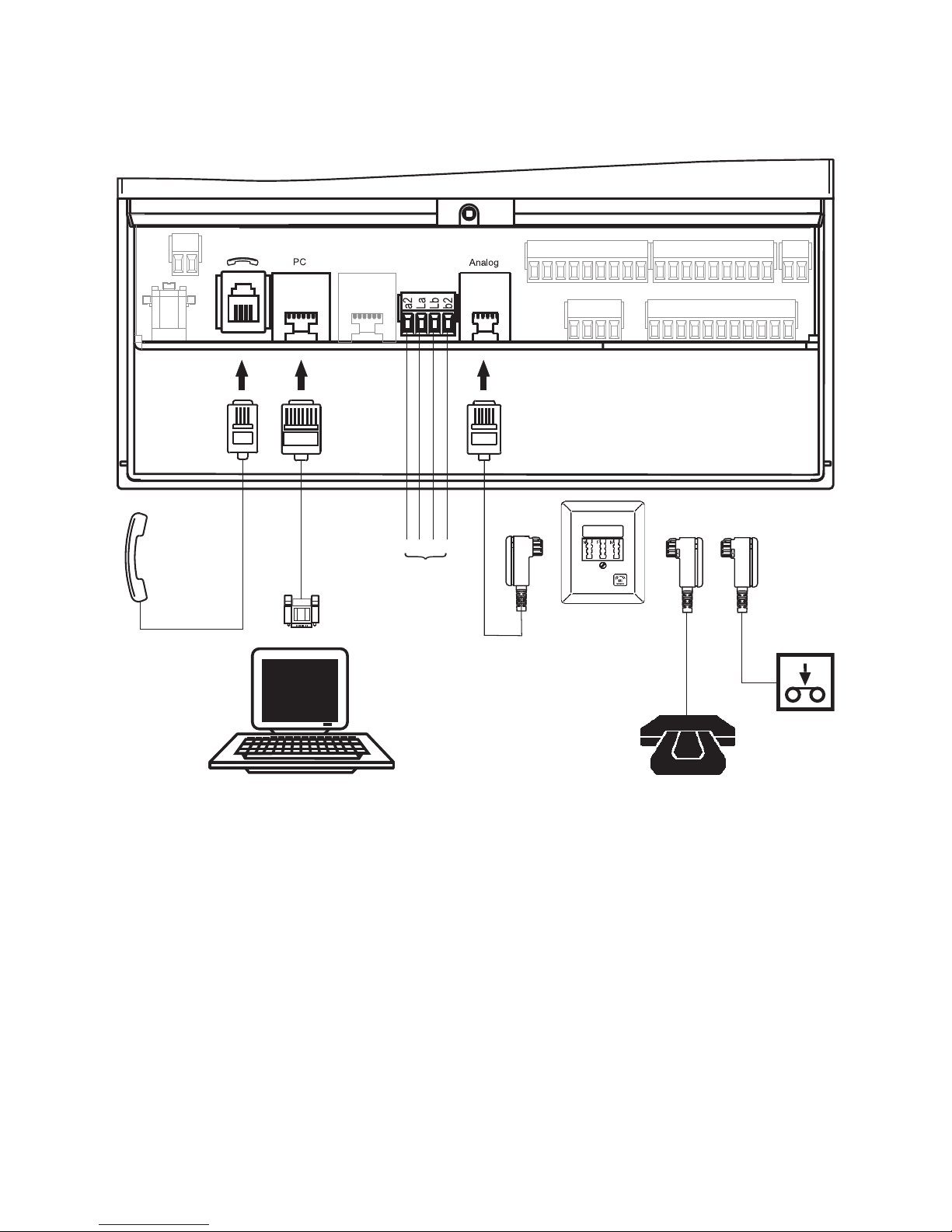
Handset
(optional)
alternative connec-
tion to the tele-
phone line
answering
machine
telephone
3.2.3 Connection to the Analog Network
3.2 Connections
PC
RS 232
10 3 Installation

external alarm confir-
mation push-button
(optional)
Using the external alarm confirmation push-button you can
locally reset the alarm, i. e.
the alarm message can be
stopped manually. By pressing
the external alarm confirmation
push-button all alarms having
occurred so far will be confirmed.
3.2 Connections
3.2.5 Transparent Switching
By closing an external potential-free switch the TeleCoppler 2 is switched transparent, i. e. without function. It
has neither the function of re-
mote switching nor the function of alarming.
The message “Switched off”
will appear on the display of
the TeleCoppler 2. The state
of the active inputs and outputs will stay on the display.
potential-free switch
3 Installation 11
3.2.4 Connection to External Alarm Confirmation Push-Button
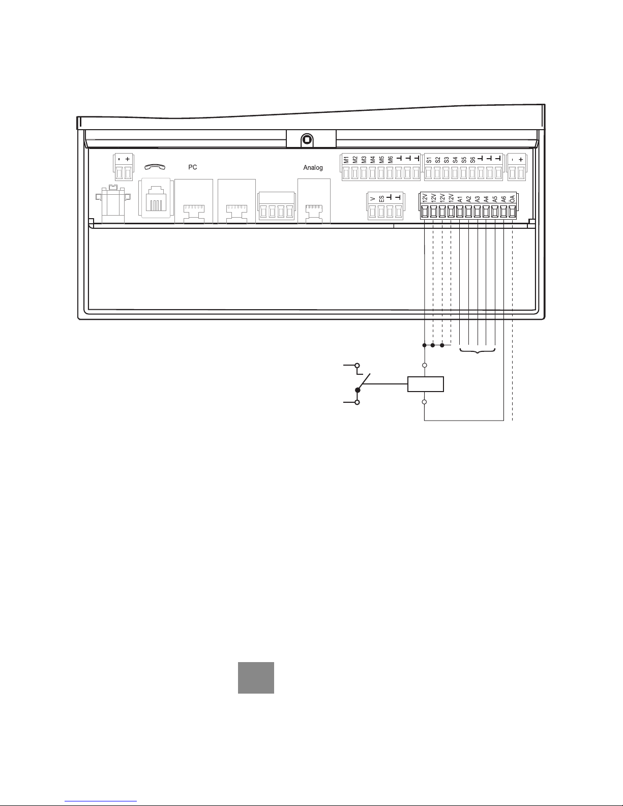
3.2.6 Switching Output Assignment
conventional device
(230 V)
relay 12 V DC
(100 mA)
as A6
local alarm
(as A6)
The TeleCoppler 2 provides 6
outputs with 12 V DC. Via relays 6 conventional devices
and, additonally, 1 local alarm
detector can be connected.
Using the enclosed plug
power supply (15 W; 1.25 A)
these relay outputs are able
each to carry 200 mA at the
maximum and they are shortcircuit proof. Current consumption of the control relay
should not exceed 100 mA. In
idle mode current consumption of the TeleCoppler 2
amounts to app. 150 mA.
The outputs consist of opencollector outputs of transistors. Between the terminal
screws +12V and A1 a relay
coil is switched on. When
switched on, the output A1 is
connected to ground. When
switched off, it has an undefined potential.
When switching the
outputs, please observe that the provided plug power supply
has a maximum performance
of 1.25 A.
3.2 Connections
12 3 Installation
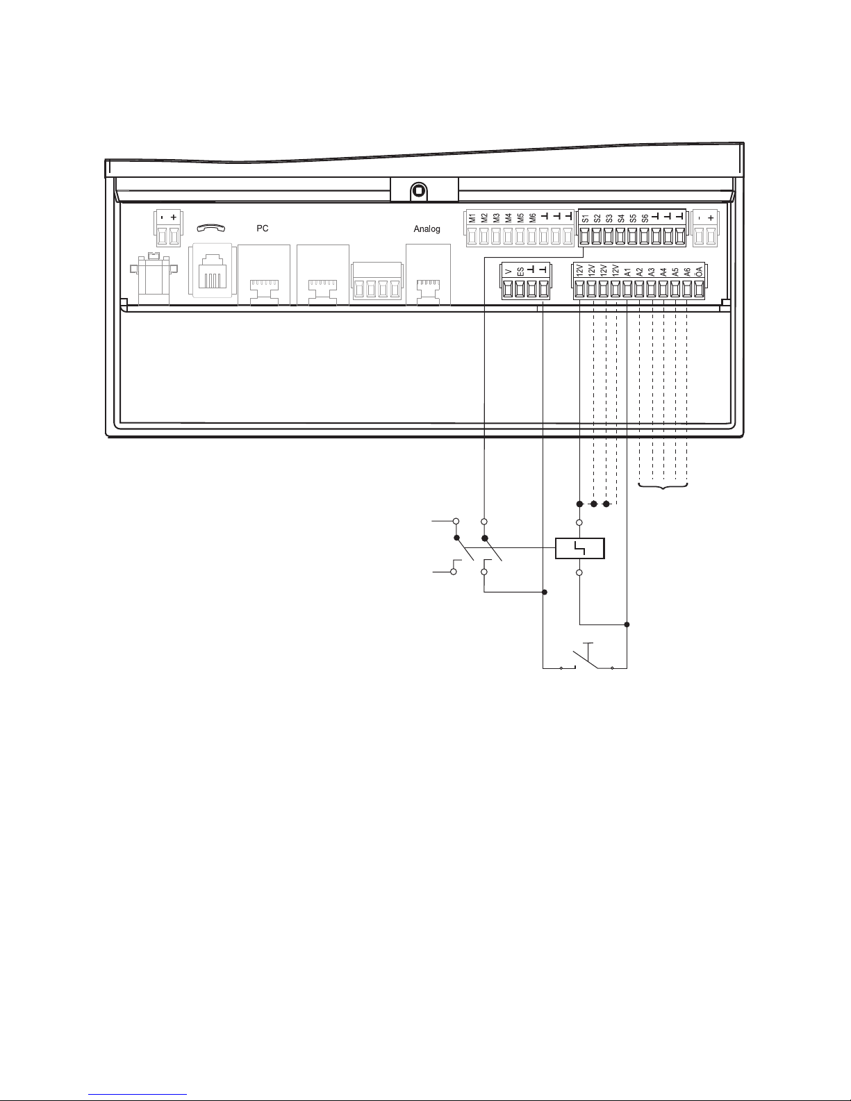
3.2.7 Operation with Current-Impulse Switches
as A1
push-button for
manual switching
conventional device
(230 V)
currentimpulse
switch
12 V DC
The TeleCoppler 2 is drafted
for switching electrical devices
by telephone. Each switching
process by telephone is
saved in the TeleCoppler 2.
And on request, the announcement is made, whether
the connected devices are
switched on or off.
For some applications the installation of an additional local
switching possibility is usefull
or even necessary. For example, a motion detector at a vacation home can be switched
on by telephone from the dis-
tance and at arrival at the
home switched off by pushing
the (locally) installed external
alarm push-button.
By appropriate settings in the
menu, the switching outputs
A1 to A6 are configurated as
current-impulse outputs. Current-impulse switches with 2
make contacts or change-over
contacts should be used in
order to transmit the present
switching state of the currentimpulse switches to the input
by way of these make contacts or change-over con-
tacts. The inputs S1 to S2
render the correct switching
state of the current-impulse
switches. This is important
because the announcements
are referring to the respective
states of the inputs (S1 to S6)
and not directly to the states
of the switching outputs (A1
to A6).
3.2 Connections
3 Installation 13

Now the TeleCoppler 2 is
ready for operation.
Before working on the
installation, unplug
the power supply.
Changes at the TeleCoppler 2 are only possible if
done within the limits and according to the description in
this manual.
The installation must be carried out professionally.
Please take into account, that
the performance of the TeleCoppler 2 with PABXs can be
improved, in case of a power
failure, if the TeleCoppler 2 is
installed before the PABX or if
there is an uninterruptible
power supply guaranteed.
1 Connect the conventional
devices (A1 to A6 and
ÖA), according to the diagram on page 12.
2 For operation by current-
impulse switches connect
the devices to the outputs
(see page 13) and configurate the outputs in the
menu as described on
page 34.
3 In case of analog phone
operation insert the plug
of the telephone line into
the telephone wall socket.
4 Plug power supply into
230 V outlet or connect
the external power supply
to "+" and "-". After having
plugged in the power supply the message
will appear on the display.
The display is blinking for
some seconds and then it
will change to:
Please wait
TC PLUS
O
I
00:00 Sa 27.11.04
3.3 Initial Operation
3 Installation
14 3 Installation

4 Settings 15
The user guide of the TeleCoppler 2 is supported by a 4
line 20 character display.
There the following informations can be read:
• First line:
device digit
state massage (e. g. ”line
failure”)
• Second line:
switched outputs (A) in the
following sequence:
conventional devices (1 to 6)
space
inactive outputs are not
being displayed
• Third line:
switched inputs (E) in the following sequence:
conventional devices (1 to 6)
space
inactive outputs are not being
displayed
• Fourth line:
time, day and date
TC PLUS
O12 1
I 4 678 0
08:15 Sa 27.11.04
The performance features of
the TeleCoppler 2 can be adjusted as desired. All settings
(except for time and date) will
be restored in case of a failure
of the 230 V network.
Before initial operation a few
necessary parameters are to
be programmed:
The setting is done by
turnkey. By turning the turnkey
the parameter which is supposed to be set changes its
value or its position. By pressing the turnkey the changed
parameter is fixed or the setting is confirmed.
In case of ON/OFF settings
the value changes each time
the turnkey is pressed.
By pressing the turnkey you
can also confirm a reported
alarm.
The TeleCoppler 2 will be de-
livered with the following settings:
• Amount of dial attempts:
12
• Code number: 0000
• 1st to 5th CLIP
number: none
• Amount of ringing signals:
2
• Dialing method: DTMF
• Line access number:
x (= none)
• Dial tone recognition:
Off
•Pause: 0
• Display language: English
• Answering machine mode:
Off
• Announcement texts:
are given
(see page
51)
4.3 Default Settings4.2 Display4.1 Operating Element
4 Settings

16 5 Display Menu Guide
5 Display Menu Guide
This chapter shows the
menus for the user guide of
the TeleCoppler 2. It is supposed to help you find certain
setting elements.
In general, all settings can be
performed on the PC (see
page 36) and can be
transmitted to the TeleCoppler
2 via the serial interface.
The procedures described
below are suited for small
changes performed locally or
in case there is no PC available.
A summary of all possible setting items you will find at the
end of this chapter.
The menu is being activated
by turning the turnkey in either
direction.
5 Display Menu Guide 17
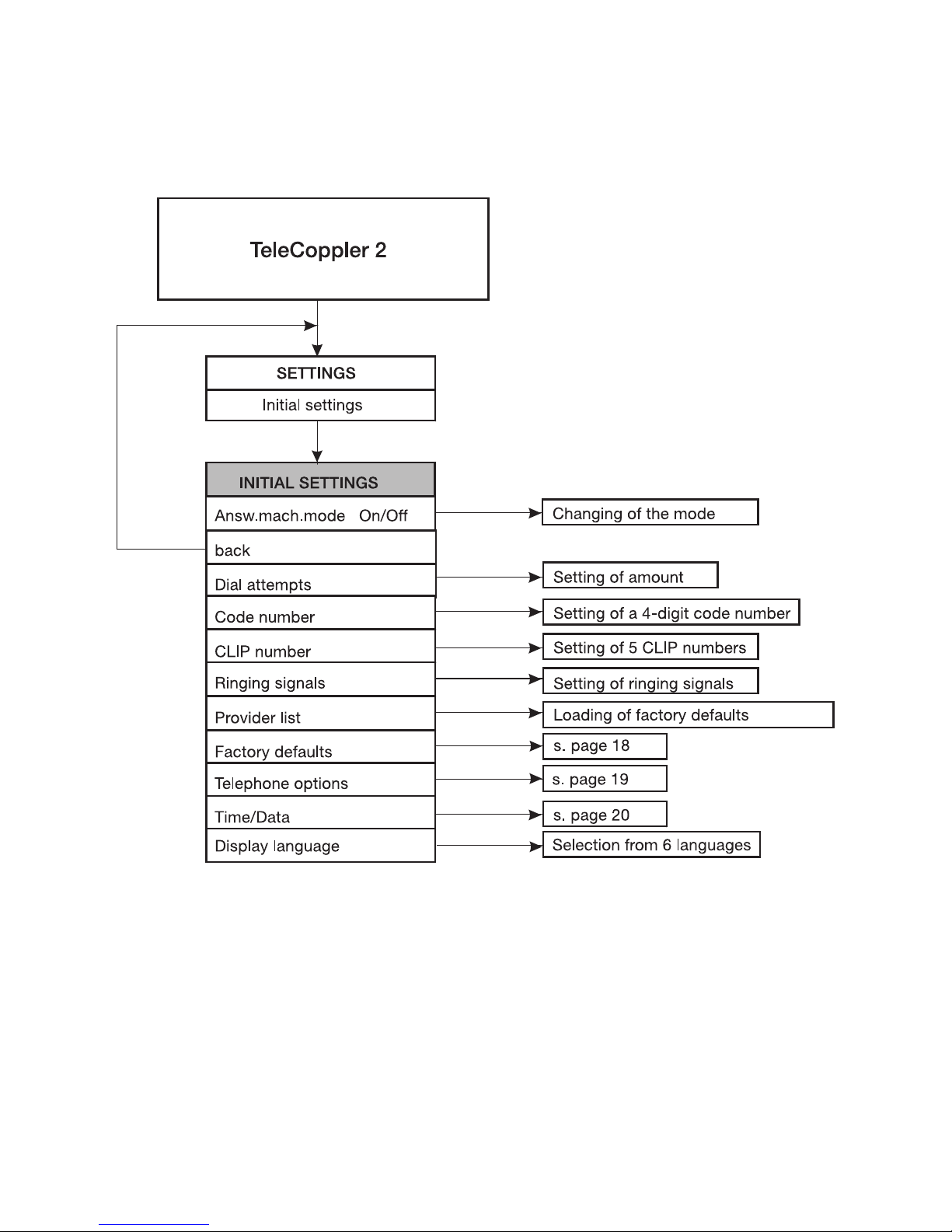
5.1 Initial Settings
5 Display Menu Guide
 Loading...