

KNX
Push-button bus coupler
1-gang water-protected surface-mounted KNX push-button bus coupler with single-point
operation
Order No. : 5151 30
1-gang water-protected surface-mounted KNX push-button bus coupler with two-point
operation
Order No. : 5152 30
2-gang water-protected surface-mounted KNX push-button bus coupler with single-point
operation
Order No. : 5161 30
2-gang water-protected surface-mounted KNX push-button bus coupler with two-point
operation
Order No. : 5162 30
Operating instructions
1 Safety instructions
Electrical equipment may only be installed and fitted by electrically skilled persons.
Serious injuries, fire or property damage possible. Please read and follow manual fully.
These instructions are an integral part of the product, and must remain with the end
customer.
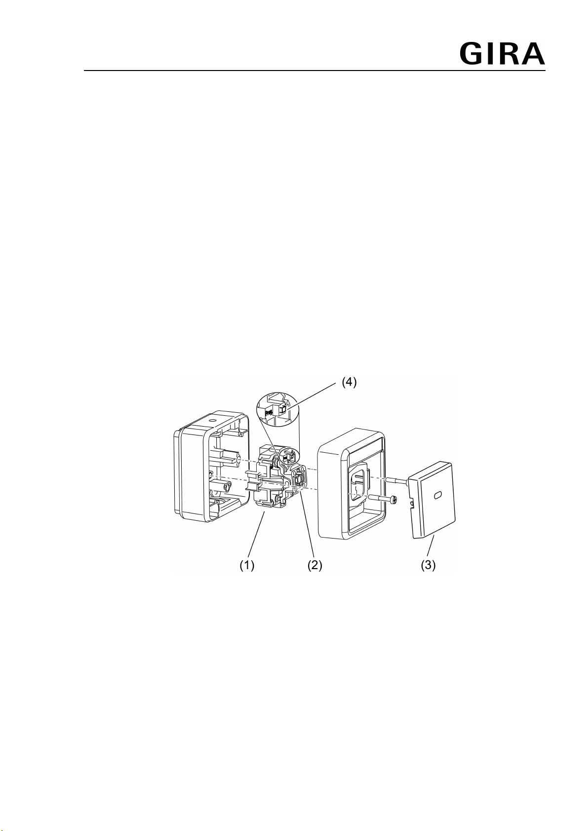
2 Device components
(1) Push-button BA
(2) Rocker switch
(3) Rocker
(4) Programming button and LED
Figure 1
3 Function
System information
This device is a product of the KNX system and complies with the KNX directives. Detailed
technical knowledge obtained in KNX training courses is a prerequisite to proper understanding.
The function of this device depends upon the software. Detailed information on loadable
software and attainable functionality as well as the software itself can be obtained from the
manufacturer´s product database. Planning, installation and commissioning of the device are
32583502 22.09.2014
10860486
1/3
KNX
Push-button bus coupler
carried out with the aid of KNX-certified software. The latest versions of product database and
the technical descriptions are available on our website.
Intended use
- Operation of loads, e.g. light on/off, dimming, blinds up/down, brightness values,
temperatures, calling up and saving light scenes, etc.
- Installation in the water-protected surface-mounted housing
Product characteristics
- Adaption of conventional switch ranges for KNX installations
- WP surface-mounted version: With water-protected surface-mounted box IP 44
Depending on the version:
- Push switch function with 1 pressure point, or rocker switch function with 2 pressure points
4 Information for electrically skilled persons
DANGER!
Electrical shock on contact with live parts in the installation environment.
Electrical shocks can be fatal.
Before working on the device, disconnect the power supply and cover up live
parts in the working environment.
4.1 Fitting and electrical connection
Connecting and fitting the device
o Connect bus line with terminal to bus connection at the back.
o Install the device in the right orientation on an appliance box. Observe the marking OBEN.
o Load physical address into the device before mounting the rockers.
o Attach operating rockers together with the corresponding frame.
4.2 Commissioning
Load the address and the application software
o Switch on the bus voltage.
o Press the programming button carefully with a suitable tool.
The programming LED lights up.
o Assign physical address.
The programming LED goes out.
o Write the physical address on the device label.
o Load the application software into the device.
5 Appendix
5.1 Technical data
KNX medium TP
Commissioning mode S-mode
Rated voltage KNX DC 21 ... 32 V SELV
Power consumption KNX typical 150 mW
Protection class III
Connection mode KNX Connection terminal
Ambient conditions
Ambient temperature -25 ... +55 °C
Storage/transport temperature -25 ... +70 °C
Relative humidity 5 ... 93 % (No moisture condensation)
Degree of protection IP 44
32583502 10860486 22.09.2014
2/3
 Loading...