

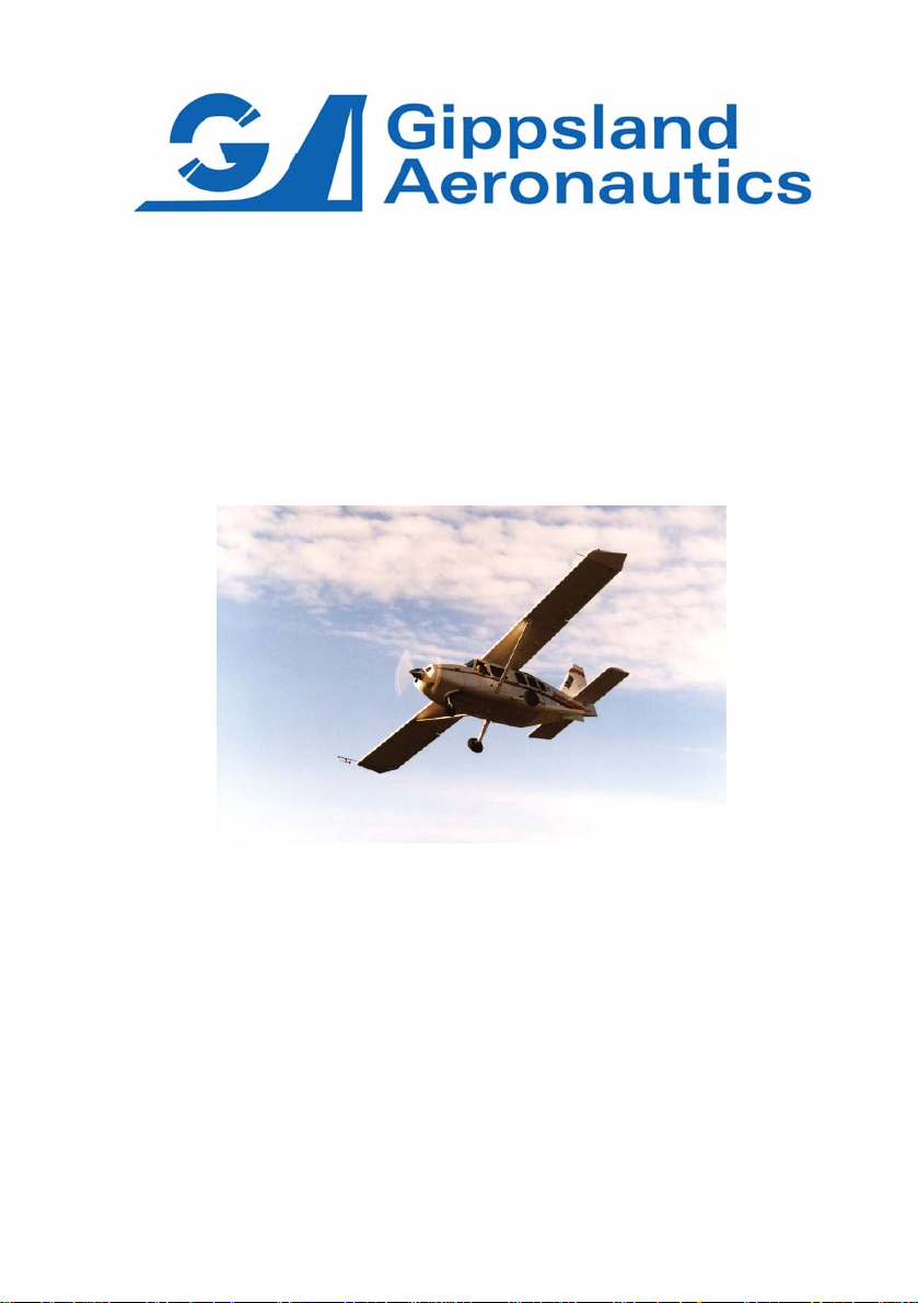
Gippsland Aeronautics GA8 Owners And Pilots Information Manual
OWNERS AND PILOTS
INFORMATION MANUAL
(For Approved Document please refer to C01-01-04)
Model GA8
THIS GA8 OWNERS AND PILOTS INFORMATION MANUAL IS FOR REFERENCE ONLY AND
THEREFORE MUST NOT BE USED AS A SUBSTITUTE FOR THE OFFICIAL CASA
AUSTRALIA APPROVED FAA ACCEPTED FLIGHT MANUAL DOCUMENT.
GA-FM-04 Owners and Pilots Information Manual Page (i)
Gippsland Aeronautics Pty Ltd
P.O. Box 881
Morwell Victoria 3840
Australia
Tel.: +61 3 5172 1200
Fax: +61 3 5172 1201

This page intentionally left blank

GIPPSLAND AERONAUTICS
Model GA8
CONTENTS
Section
1 General
2 Limitations
3 Emergency Procedures
4 Normal Procedures
5 Performance
6 Weight and Balance/Equipment List
7 Aircraft and Systems Description
8 Aircraft Handling, Servicing and Maintenance
9 Supplements
GA-FM-04 Owners and Pilots Information Manual Page (ii)

This page intentionally left blank

GIPPSLAND AERONAUTICS SECTION 1
Model GA8 GENERAL
1 SECTION 1
SECTION 1
GENERAL
TABLE OF CONTENTS
Paragraph Page
1.1 INTR DUCTIONO .........................................................................................................1-2
1.2 GENERAL DESCRIPTION..........................................................................................1-5
1.3 SYM OLS, ABBREVIATIONS AND TERMINOLOGYB ................................................1-6
1.4 USE OF METRIC/IMPERIAL UNITS.........................................................................1-11
1.1.1 Owners and Pilots Information Manual ..........................................................1-4
1.1.2 Definitions.......................................................................................................1-4
1.2.1 Aircraft............................................................................................................1-5
1.2.2 Engine............................................................................................................1-5
1.3.1 General Symbols and Abbreviations..............................................................1-6
1.3.2 General Airspeed Terminology and Symbols.................................................1-8
1.3.3 Meteorological Terminology...........................................................................1-9
1.3.4 Power Terminology ........................................................................................1-9
1.3.5 Engine Controls and Instruments...................................................................1-9
1.3.6 Aircraft Performance and Flight Planning Terminology................................1-10
1.3.7 Weight and Balance Terminology ................................................................1-10
GA-FM-04 Owners and Pilots Information Manual Page 1-1

GIPPSLAND AERONAUTICS SECTION 1
Model GA8 GENERAL
1.1 INTRODUCTION
The Owners and Pilots Information Manual consists of an introductory section and eight
additional numbered sections. These sections provide owners and pilots with familiarisation
of the GA8 Airvan in all phases of flight, ground handling terminology and servicing.
The operating procedures presented herein are the result of Gippsland Aeronautics
knowledge and experience gained over time. For specific information in regard to this
Information Manual, please contact:
Gippsland Aeronautics Pty Ltd
P.O. Box 881
Morwell Victoria 3840
Australia
Tel.: +61 3 5172 1200
Fax: +61 3 5172 1201
Email: techrec@gippsaero.com
Page 1-2 Owners and Pilots Information Manual GA-FM-04
GIPPSLAND AERONAUTICS SECTION 1
Model GA8 GENERAL
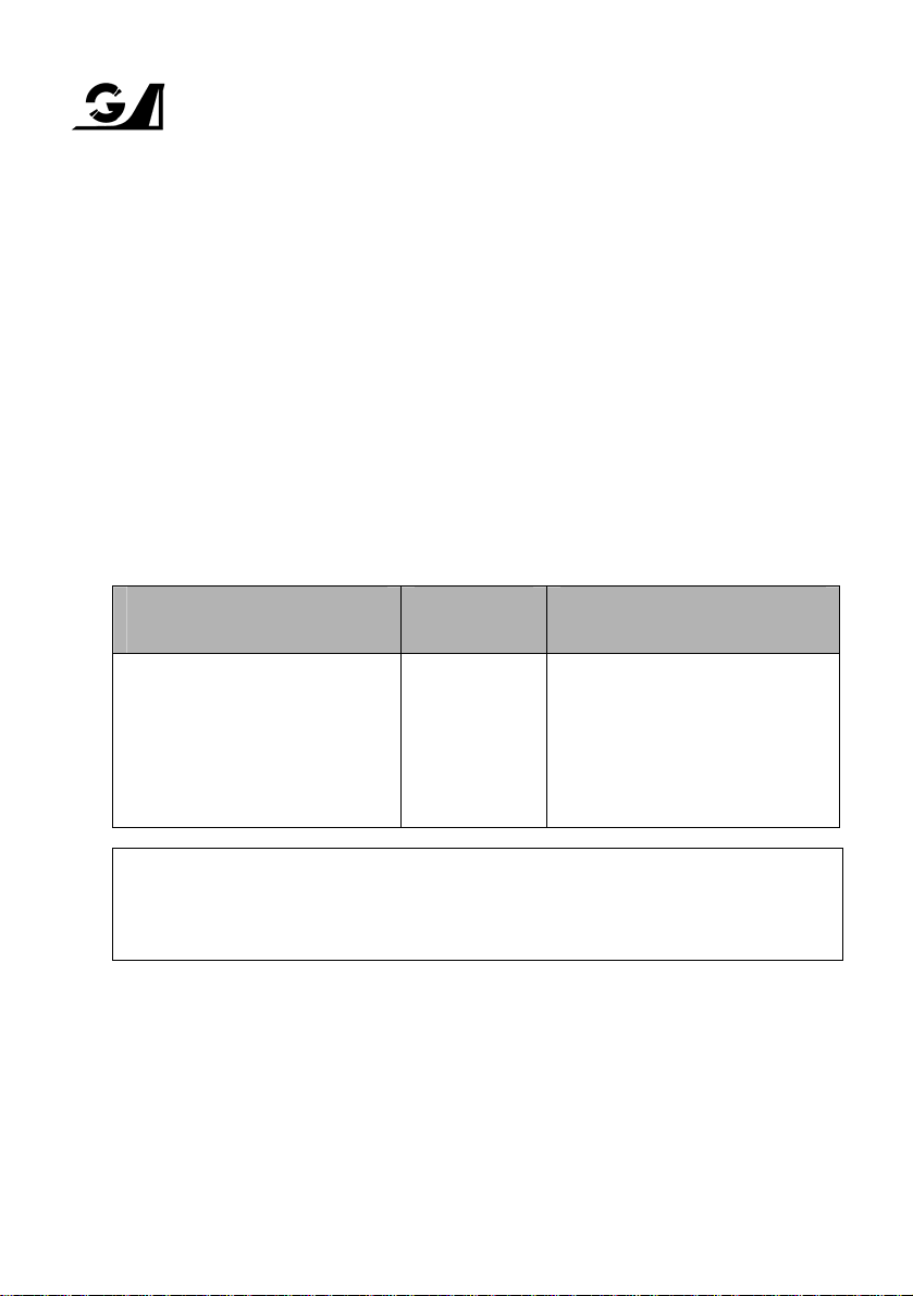
352.3 [8949]
153.0 [3885]
33.5 [851]
90.5 [2299]
94.0 [2388]
FLOOR LINE
GROUND LINE
164 [4166]
94.0 [2388]
63.0 [1600]
FIREWALL LINE
488.68 [12412]
Ø84.0 [Ø2134] MAX
2.5° DIHEDRAL
FLOOR LINE
GROUND LINE
110.0 [2794]
Figure 1-1 Three View of the GA8
Note: All dimensions in inches and [millimetres] Pilot’s Operating Handbook (POH)
GA-FM-04 Owners and Pilots Information Manual Page 1-3

GIPPSLAND AERONAUTICS SECTION 1
Model GA8 GENERAL
1.1.1 Owners and Pilots Information Manual
The Owners and Pilots Information Manual provides all required details of the standard
aircraft and the procedures required to operate it in the normal category. Apart from the
listing in Section 6, no other details of any optional equipment fitted at the factory will be
found in the basic Owners and Pilots Information Manual.
1.1.2 Definitions
Definitions used in the Owners and Pilots Information Manual such as WARNING,
CAUTION, NOTE are employed in the following context:
WARNING
Operating procedures, techniques, etc. which if not followed correctly,
may result in personal injury or death.
CAUTION
Operating procedures, techniques, etc. which if not strictly observed,
may result in damage to the aircraft or to its installed equipment.
NOTE
Operating procedures, techniques, etc. which it is considered essential
to highlight.
Page 1-4 Owners and Pilots Information Manual GA-FM-04

GIPPSLAND AERONAUTICS SECTION 1
Model GA8 GENERAL
1.2 GENERAL DESCRIPTION
1.2.1 Aircraft
The GA8 aircraft is a strut braced, high wing, fixed tricycle undercarriage, single engine,
eight seat cabin aircraft that has been designed primarily for passenger and utility
operations.
The fuselage is an all alloy stressed skin construction and is fully corrosion protected. The
floor of the passenger cabin is provided with a quick release system to allow rapid
conversion from freight to passenger or combi configurations. The engine cowlings are
manufactured from composite materials and feature large, easily removable access panels.
The cockpit is designed to accommodate the pilot in command on the left side and all
controls, instruments, selectors and switches are located so as to be within easy reach of
the occupant of that seat. A second, optional set of flight controls and instruments may be
fitted to the right side front seat position. The centrally located control pedestal, radio stack
and overhead switch panel are accessible from either of the two cockpit seats. The cockpit
is accessed by forward hinging doors that are located on each side. The main cabin is
provided with a large sliding door on the left side at the rear of the fuselage.
The wings are of all metal stressed skin construction with full corrosion protection, and are
braced on each side by a single streamlined bracing strut. A single integral fuel tank is
located in each wing between the fuselage and the strut. The ailerons and wing flaps are of
metal construction and operate in a conventional sense.
The empennage is also an all metal stressed skin construction and is fully corrosion
protected. A variable incidence stabiliser is incorporated to provide a wide trim range with
maximum aerodynamic efficiency. The vertical surfaces feature a half span rudder that is
located on the lower portion of the fin.
1.2.2 Engine
The engine is a, six cylinder, horizontally opposed, air cooled, normally aspirated and fuel
injected Lycoming IO-540-K1A5 rated by Lycoming to 300 BHP at full throttle and 2700
RPM. Operations at 2700 RPM are limited to a maximum period of two minutes. Except for
take-off, normal full throttle operations are conducted using 2500 RPM.
GA-FM-04 Owners and Pilots Information Manual Page 1-5

GIPPSLAND AERONAUTICS SECTION 1
Model GA8 GENERAL
1.3 SYMBOLS, ABBREVIATIONS AND TERMINOLOGY
1.3.1 General Symbols and Abbreviations
A Ampere
AGL Above Ground Level
AMSL Above Mean Sea Level
AVGAS Aviation Gasoline
BHP Brake Horse Power
CASA Civil Aviation Safety Authority (Australia)
CAO Civil Aviation Order (Australia)
CAR Civil Aviation Regulation (Australia)
°C Degrees Celsius
CHT Cylinder Head Temperature
cm Centimetre, centimetres
DC Direct Current
E East
EMERG Emergency
FAA Federal Aviation Administration (USA)
°F Degrees Fahrenheit
FAR Federal Aviation Regulation (USA)
ft Foot, feet
ft/min Feet per minute
g Acceleration due to gravity
Gal Gallon
GAMA General Aviation Manufacturers Association
hPa Hectopascal, hectopascals
HF High Frequency
ICAO International Civil Aviation Organisation
ICO Idle Cut Off
IFR Instrument Flight Rules
IMC Instrument Meteorological Conditions
in Inch, inches
in Hg Inches of mercury
in lbs Inch pounds
incr. increase
ISA International Standard Atmosphere
kg Kilogram
kg/l Kilogram per litre
kHz Kilohertz
kts, K Knots
kPa Kilopascals
kW Kilowatt, kilowatts
l Litre, litres
lb Pound, pounds
LH Left Hand
LHS Left Hand Side
Page 1-6 Owners and Pilots Information Manual GA-FM-04

GIPPSLAND AERONAUTICS SECTION 1
Model GA8 GENERAL
m Metre
m
m
2
Square metre
3
Cubic metre
mA Milli ampere
MAC Mean Aerodynamic Chord
MAN Manual
MAP Manifold Air Pressure
max Maximum
MCP Maximum Continuous Power
MHz Megahertz
mm Millimetre
min Minimum or minute
m kg Metre kilogram
N North
NM Nautical mile, nautical miles
OAT Outside Air Temperature
PAX Passenger
POH Pilots Operating Handbook
PPH Pounds per hour
PPM Parts per million
PROP Propeller
psi Pounds per square inch
PWR Power
QTY Quantity
qts Quarts
RH Right Hand
RHS Right Hand Side
RPM Revolutions per minute
S South
SAE Society of Automotive Engineers
sec Seconds
SPKR Speaker
SQ Square
SSB Single Side Band
STBY Standby
SYST System
TBO Time between overhauls
T/O Take Off
US United States (of America)
U/S Unserviceable
USA United States of America
USG US Gallon
US Gal US Gallon
V Volts
VFR Visual Flight Rules
VHF Very High Frequency
VMC Visual Meteorological Conditions
W West
GA-FM-04 Owners and Pilots Information Manual Page 1-7

GIPPSLAND AERONAUTICS SECTION 1
Model GA8 GENERAL
1.3.2 General Airspeed Terminology and Symbols
CAS Calibrated Airspeed: the indicated speed of an aircraft corrected for position
and instrument error. Calibrated airspeed is equal to true airspeed in standard
atmosphere at sea level.
KCAS Calibrated Airspeed expressed in knots.
GS Ground Speed: t he speed of an aircraft relative to the ground.
IAS Indicated Airspeed: the speed of an aircraft as shown on the airspeed
indicator. IAS values in this manual assume zero instrument error.
KIAS Indicated Airspeed expressed in knots.
TAS True Air Speed: the airspeed of an aircraft relative to the undisturbed air
through which it passes.
T.O.S.S Take-Off Safety Speed: the airspeed chosen to ensure that adequate control
will exist under all conditions, including turbulence and sudden and complete
engine failure during the climb after take-off. It is the speed required at 50 feet.
Manoeuvring Speed: the maximum speed at which application of full available
V
A
aerodynamic control will not damage or overstress the aircraft.
Maximum Flap Extended Speed: the highest speed permissible with wing flaps
V
FE
in a prescribed extended position.
Never Exceed Speed: the limiting airspeed that may not be exceeded at any
V
NE
time.
Maximum Structural Cruising Speed: the speed that should not be exceeded
V
NO
except in smooth air and then only with caution.
VS Stalling Speed: or the minimum steady flight speed at which the aircraft is
controllable.
Stalling Speed: or the minimum steady flight speed at which the aircraft is
V
SO
controllable in the landing configuration.
Best Angle-of-Climb Speed: the airspeed which delivers the greatest gain of
V
X
altitude in the shortest possible horizontal distance.
Best Rate-of-Climb Speed: the airspeed which delivers the greatest gain in
V
Y
altitude in the shortest possible time.
Reference Landing Approach Speed: the airspeed equal to 1.3VSO and is the
V
REF
airspeed used on approach down to 50 feet above the runway when
determining landing distances.
Page 1-8 Owners and Pilots Information Manual GA-FM-04

GIPPSLAND AERONAUTICS SECTION 1
Model GA8 GENERAL
1.3.3 Meteorological Terminology
ISA International Standard Atmosphere in which:
The air is a dry perfect gas:
The temperature at sea level is 15°C (59°F):
The pressure at sea level is 1013 hPa (29.92 inches Hg):
The temperature gradient from sea level to the altitude at which the
temperature is -56.5°C (-69.7°F) is 0.00198°C (0.003566°F) per foot, and ze ro
above that altitude.
OAT (Outside Air Temperature) The outside free air static temperature.
Airfield Pressure Height The height registered at the surface of an aerodrome by an
altimeter with the pressure sub-scale set to 1013 hPa (29.92 inches Hg).
Pressure Altitude Altitude measured from standard sea-level pressure (1013 hPa/29.92
inches Hg) by a pressure or barometric altimeter corrected for position and instrument error.
Indicated Pressure Altitude The altitude actually read from an altimeter when the
pressure barometric sub-scale has been set to 1013 hPa (29.92 inches Hg).
Station Pressure Actual atmospheric pressure at field elevation.
QNH The local pressure setting that if set on the subscale of an altimeter will cause the
altimeter to indicate local altitude above mean sea level.
Wind The wind velocities to be used as variables on aircraft performance are to be
understood as the headwind or tail wind components of the reported winds.
1.3.4 Power Terminology
Take-Off Power Maximum power permissible for take-off.
Maximum Continuous Power Maximum power that is allowed to be used continuousl y
during flight.
1.3.5 Engine Controls and Instruments
Throttle Lever The lever which the pilot uses to control the engine manifold pressure.
Pitch Lever The lever which the pilot uses to control the engine RPM
Mixture Control The control that is used to vary the fuel/air ratio available to the engine.
MAP Gauge The instrument that indicates engine inlet Manifold Air Pressure
Tachometer The instrument that indicates the engine RPM.
GA-FM-04 Owners and Pilots Information Manual Page 1-9

GIPPSLAND AERONAUTICS SECTION 1
Model GA8 GENERAL
1.3.6 Aircraft Performance and Flight Planning Terminology
Climb Gradient The ratio of the change in height during a climb, to the horizontal distance
travelled.
Demonstrated Crosswind Component The crosswind component, during take-off and
landing, for which adequate control of aircraft was actually demonstrated during certification
tests.
1.3.7 Weight and Balance Terminology
Reference Datum An imaginary vertical plane from which all horizontal distances are
measured for balance purposes.
Station A location along the aircraft fuselage usually given in terms of distance from the
reference datum.
Arm The horizontal distance from the reference dat um to the centre of gravity (C of G) of
an item.
Moment The product of the weight of an item multiplied by its arm.
Index Unit Moment divided by a constant. Used to simplify balance calculations by
reducing the number of digits.
Centre of Gravity (C of G) The point at which an aircraft would balance if suspended.
The distance from the C of G to the reference datum can be found by dividing the total
moment by the total weight of the aircraft.
C of G Arm The arm obtained by adding the aircraft's individual moments and dividing the
sum by the total weight.
C of G Limits The extreme centre of gravity locations within which the aircraft must be
operated at a given weight.
Useable Fuel The quantity of fuel available for flight planning purposes.
Unusable Fuel The quantity of fuel (determined under adverse fuel flow conditions) that is
not available for flight.
Empty Weight Weight of aircraft with unusable fuel and undrainable oil.
Basic Empty Weight Usually defined as empty weight plus full oil.
Useful Load Difference between take-off weight, and basic empty weight.
Maximum Take-Off Weight Maximum weight approved for take-off.
Maximum Landing Weight Maximum weight approved for the landing.
Page 1-10 Owners and Pilots Information Manual GA-FM-04

GIPPSLAND AERONAUTICS SECTION 1
Model GA8 GENERAL
1.4 USE OF METRIC/IMPERIAL UNITS
This Owners and Pilots Information Manual uses the Imperial/US unit system as the basic
system of measurement. Where common usage or available instrumentation refer to the metric
system, both units are quoted. The following conversion factors are presented as a ready
reference to the conversion factors that have been used in this manual as well as supplying
some others that may be found useful.
1 Pound (lb) = 0.4536 Kilogram (kg)
1 Pound per sq in (psi) = 6.895 Kilopascal (kPa)
1 Inch (in) = 25.4 Millimetres (mm)
1 Foot (ft) = 0.3048 Metre (m)
1 Statute mile = 1.609 Kilometres (km)
1 Nautical mile (NM) = 1.852 Kilometres (km)
1 Millibar (mb) = 1 Hectopascal (hPa)
1 Millibar (mb) = 0.1 Kilopascal (kPa)
1 Imperial gallon = 4.546 Litres (l)
1 US gallon = 3.785 Litres (l)
1 US quart = 0.946 Litre (l)
3
1 Cubic foot (ft
) = 28.317 Litres (l)
1 Acre = 0.4047 Hectares
1 Degree Fahrenheit (°F) = [1.8 x °C]+32
1 Inch Pound (in lb) = 0.113 Newton Metres (Nm)
1 Foot Pound (ft lb) = 1.356 Newton Metres (Nm)
GA-FM-04 Owners and Pilots Information Manual Page 1-11

GIPPSLAND AERONAUTICS SECTION 1
Model GA8 GENERAL
This page intentionally left blank
Page 1-12 Owners and Pilots Information Manual GA-FM-04

GIPPSLAND AERONAUTICS SECTION 2
Model GA8 LIMITATIONS
2 SECTION 2
SECTION 2
LIMITATIONS
TABLE OF CONTENTS
Paragraph Page
2.1 GENERAL....................................................................................................................2-2
2.2 AIRSPEED LIMITATIONS...........................................................................................2-2
2.3 AIRSPEED INDICATOR MARKINGS..........................................................................2-2
2.4 POWER PLANT LIMITATIONS...................................................................................2-3
2.5 ENGINE INSTRUMENT MARKINGS ..........................................................................2-5
2.6 WEIGHT LIMITS..........................................................................................................2-5
2.7 CENTRE OF GRAVITY LIMITS...................................................................................2-5
2.8 MANOEUVRE LIMITS.................................................................................................2-6
2.9 FLIGHT LOAD FACTOR LIMITS.................................................................................2-6
2.10 FLIGHT CREW LIMITS ...............................................................................................2-6
2.11 KINDS OF OPERATION LIMITS .................................................................................2-6
2.12 FUEL LIMITATIONS..................................................................................................2-10
2.13 MAXIMUM PASSENGER SEATING LIMITS.............................................................2-10
2.14 OTHER LIMITATIONS...............................................................................................2-10
2.15 PLACARDS ...............................................................................................................2-11
2.4.1 Engine............................................................................................................2-3
2.4.2 Engine Limitations..........................................................................................2-3
2.4.3 Fuel Grade .....................................................................................................2-3
2.4.4 Lubricating Oil ................................................................................................2-4
2.4.5 Propeller.........................................................................................................2-5
GA-FM-04 Owners and Pilots Information Manual Page 2-1
GIPPSLAND AERONAUTICS SECTION 2
Model GA8 LIMITATIONS
2.1 GENERAL
This section of the Owners and Pilots Operating Manual presents the various operating
limitations, instrument markings, colour coding, and basic placards necessary for the safe
operation of the aircraft, it's engine, standard systems and standard equipment.
All limitations contained in this section have been approved by the Australian Civil Aviation
Safety Authority, and operation in compliance with the limitations presented in this section is
required by the Federal Aviation Regulations.
For specific operations, or for operations with equipment fitted that is covered by a supplement,
any limitations applicable will be found in the relevant supplement.
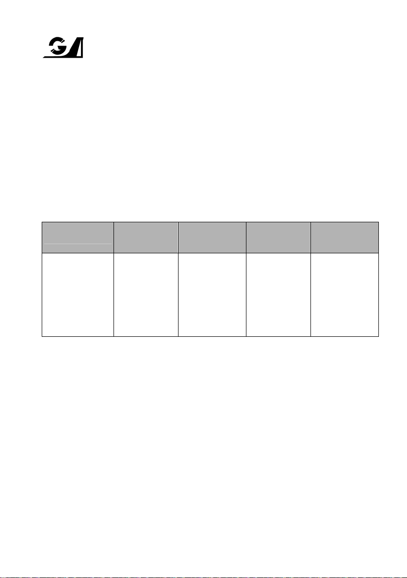
2.2 AIRSPEED LIMITATIONS
The indicated airspeeds in the table below are based on airspeed calibration data from Section 5.
SPEED KCAS KIAS REMARKS
Max Manoeuvring Speed (VA) 124 121
Never Exceed Speed (VNE) 183 185
Max Structural Cruising Speed (VNO) 145 143
Do not make full or abrupt control
movements above this speed.
Do not exceed this speed in any
operation.
Do not exceed this speed except in
smooth air and then with caution.
2.3 AIRSPEED INDICATOR MARKINGS
The airspeed indicator markings in the table below are based on airspeed calibration data from
Section 5.
MARKING IAS VALUE or RANGE SIGNIFICANCE
White Arc
Green Arc 64 - 143
Yellow Arc 143 - 185
Red Line 185 Maximum speed for all operations (VNE).
57 - 97
Full Flap Operating Range. Lower limit is the maximum
weight stalling speed in the landing configuration. Upper
limit is the maximum speed with flaps fully extended.
Normal Operating Range. Lower limit is the maximum
weight stalling speed with flaps retracted. Upper limit is
the maximum structural cruising speed.
Operations must be conducted with caution and only in
smooth air.
Page 2-2 Owners and Pilots Information Manual GA-FM-04
GIPPSLAND AERONAUTICS SECTION 2
Model GA8 LIMITATIONS
2.4 POWER PLANT LIMITATIONS
2.4.1 Engine
Manufacturer: Textron Lycoming Division
Textron Corporation
Model: Lycoming IO-540-K1A5
2.4.2 Engine Limitations
POWER RPM
Maximum
Take-Off
(300 BHP)
Maximum
Continuous
(275 BHP)
2700
(max. 2
minutes)
2500 Full Throttle
2700 RPM may only be used for take-off to a safe height as required to clear
obstacles or reach 250ft AGL. Operations at 2700 RPM are limited to a maximum
period of two minutes. For all other operations maximum power is to be limited to
MCP at 2500 RPM.
Other limits are as follows:
1. Minimum fuel pressure at idle: 12 psi (83 kPa)
2. Minimum oil pressure at idle: 25 psi (173 kPa)
3. Maximum oil pressure at start: 115 psi (793 kPa)
2.4.3 Fuel Grade
Avgas 100LL, Avgas 100/130
MANIFOLD
PRESSURE
Full Throttle
MAXIMUM
TEMPERATURES
Cyl
Head
260°C
(500°F)
260°C
(500°F)
Oil Min Max Min Max
118°C
(245°F)
118°C
(245°F)
NOTE
NOTE
PRESSURE LIMITS (See Notes)
FUEL OIL
18 psi
(124 kPa)
18 psi
(124 kPa)
55 psi
(379 kPa)
55 psi
(379 kPa)
55 psi
(379 kPa)
55 psi
(379 kPa)
95 psi
(654 kPa)
95 psi
(654 kPa)
NOTE
For fuel tank capacities refer to section 2.12 Fuel Limitations
GA-FM-04 Owners and Pilots Information Manual Page 2-3
GIPPSLAND AERONAUTICS SECTION 2
Model GA8 LIMITATIONS
2.4.4 Lubricating Oil
1. Specification:
Textron Lycoming Specification No. 301F approves lubricating oils of any brand name
conforming to specifications MIL-L-6082 for straight mineral oil and MIL-L-22851 for ashless
dispersant oil.
Straight mineral oil must be used during the first 50 hours of operation for new and
overhauled engines, or until the oil consumption has stabilised. After the first 50 hours it is
recommended that ashless dispersant oil be used.
Refer to Lycoming Service Instruction No.1014 for further details.
2. Viscosity Grade:
The following chart is intended to assist in choosing the correct grade of oil and must be
considered as a guide only. Multiviscosity grades can also be used as indicated. Refer to
Lycoming Service Instruction No. 1014 for further details.
Average
Ambient Temperature
All Temperatures
Above 27°C (80°)
Above 16°C (60°F)
-1°C (30°F) to 32°C (90°F)
-18°C (0°F) to 21°C (70°F)
Below –12°C (10°F)
Equivalence of SAE and commonly used
Commercial Grade designations:
SAE: 20 30 40 50 60
Commercial: 55 65 80 100 120
3. Capacity:
Total: 12 US quarts (11.4 litres)
Useable: 9.3 US quarts (8.8 litres)
Min safe: 2.8 US quarts (2.7 litres)
Dipstick is calibrated in US quarts
Mineral
Grades
SAE 60
SAE 50
SAE 40
SAE 30
SAE 20
WARNING
SAE 15W50 or 20W50
SAE 60
SAE 40 or SAE 50
SAE 40
SAE 40, 30, 20W40
SAE 30, 20W30
Ashless Dispersant
Grades
Page 2-4 Owners and Pilots Information Manual GA-FM-04
GIPPSLAND AERONAUTICS SECTION 2
Model GA8 LIMITATIONS
2.5 ENGINE INSTRUMENT MARKINGS
2.4.5 Propeller
Manufacturer: Hartzell Propeller Inc.
Model: HC-C2YR-1BF/F8475R
Type: Metal, Constant Speed
Number of blades: 2
Diameter: 84 inches (2134 mm) maximum
78 inches (1981 mm) minimum
Max RPM: 2700
Instrument
Tachometer
Manifold Pressure
Oil Pressure
Oil Temperature
Fuel Pressure
Fuel Quantity
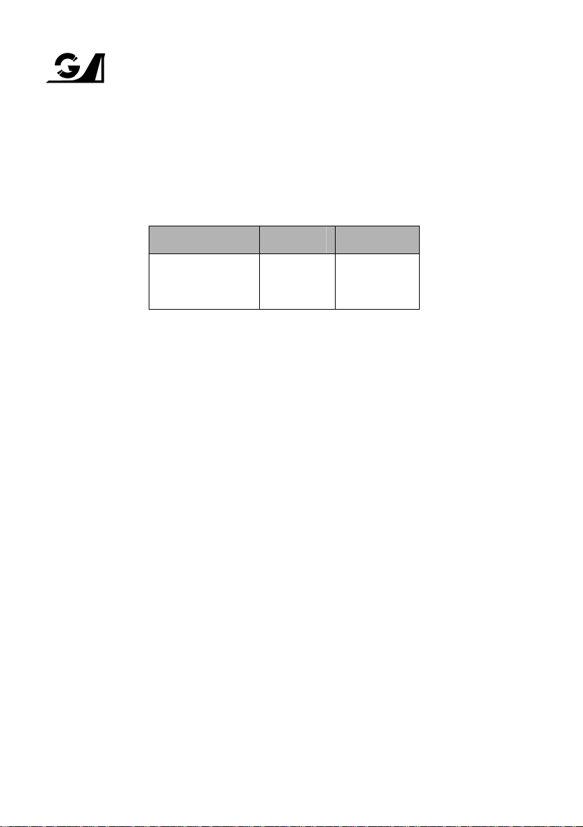
2.6 WEIGHT LIMITS
Maximum Take-Off and Landing Weight: ....................................... 4000 lb (1814 kg)
Maximum Weight on Main Cargo Area:.......................................... 1500 lb (680 kg)
Maximum Weight on Cabin Baggage Shelf:................................... 250 lb (113 kg)
Maximum Weight in Aft Luggage Bin:............................................. 50 lb (22 kg)
2.7 CENTRE OF GRAVITY LIMITS
Forward Limit: 48 inches (1219 mm) aft of datum at 2400 lbs (1089 kg) and below;
Aft Limit: 64 inches (1626 mm) aft of datum at all weights
Datum: Firewall (Fuselage Station 0)
[located 41.63 inches (1057 mm) forward of wing leading edge]
Red Line
Minimum Limit
- 575 - 2500 RPM 2700 RPM 2500 - 2700 RPM
- 10 - 30 in Hg - -
25 psi 55 - 95 psi 115 psi
-
12 psi 18 - 55 psi 55 psi 12 - 18 psi
0 0 - F - -
56 inches (1422 mm) aft of datum at 4000 lbs (1814 kg), linear variation
between these points.
Green Arc
Normal Operating
60°C - 118°C 118°C
Red Arc/Line
Maximum Limit
Yellow Arc
Precautionary
Range
25 - 55 psi
95 - 115 psi
-
GA-FM-04 Owners and Pilots Information Manual Page 2-5
GIPPSLAND AERONAUTICS SECTION 2
Model GA8 LIMITATIONS
2.8 MANOEUVRE LIMITS
All aerobatic manoeuvres including spins are prohibited.
2.9 FLIGHT LOAD FACTOR LIMITS
Flap Position Positive Negative
UP
DOWN
2.10 FLIGHT CREW LIMITS
Minimum flight crew is one pilot.
2.11 KINDS OF OPERATION LIMITS
This aircraft is approved for the following types of operations when the required equipment is
installed and operational:
- VFR Day and Night
- IFR
Icing
Flight into known icing conditions is prohibited.
Operation Equipment List
Table 2-11 summarises the equipment required under Federal Aviation Regulations (FAR) Part
23 for airworthiness under the listed kind of operation. Refer to relevant local operating rule
requirements for additional equipment that may be necessary operationally.
+ 3.8g
+ 2.0g
- 1.52g
0g
Additional equipment may be fitted to the aircraft but which is not essential for flight.
Page 2-6 Owners and Pilots Information Manual GA-FM-04
GIPPSLAND AERONAUTICS SECTION 2
Model GA8 LIMITATIONS
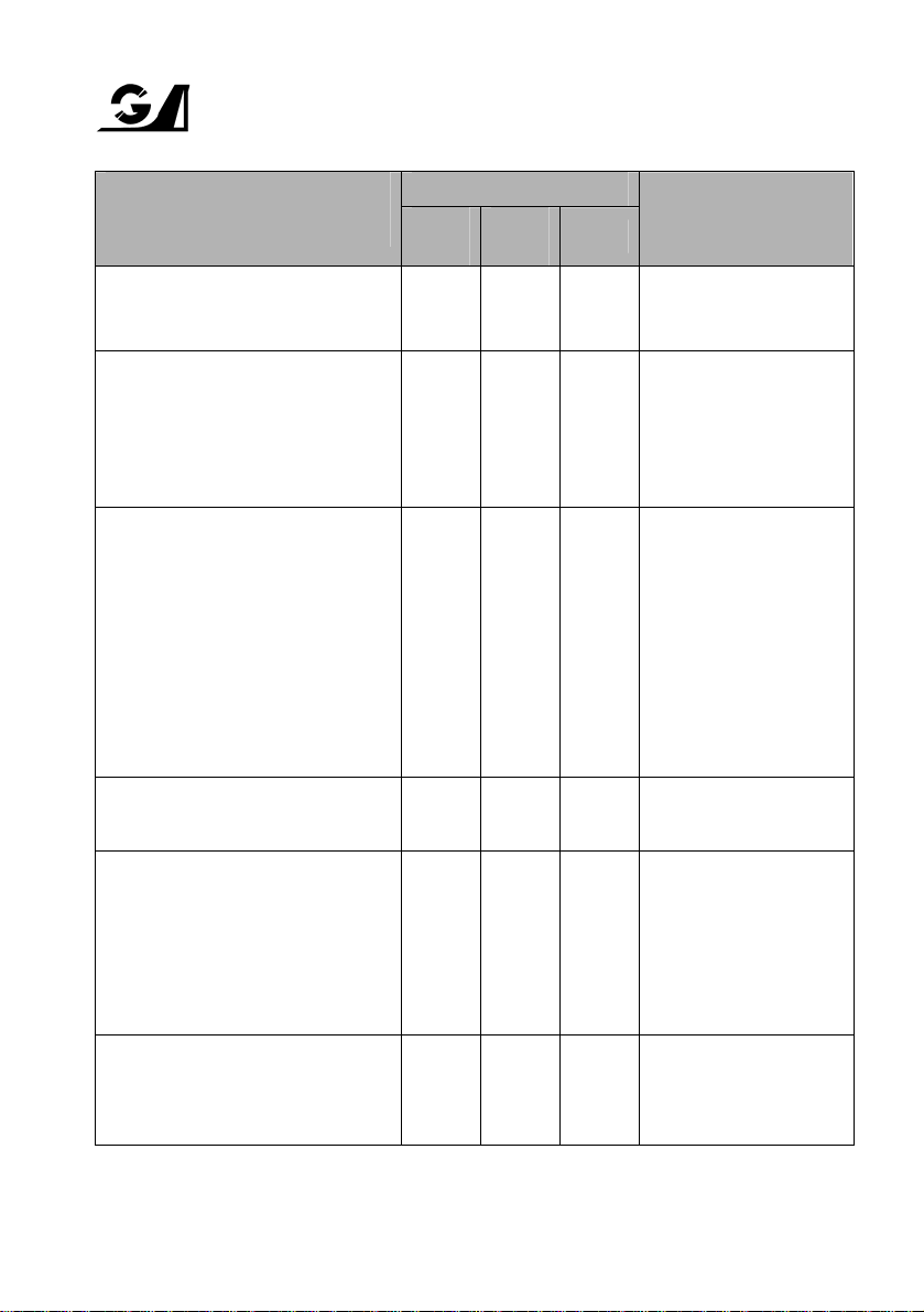
System Instruments and/or
Equipment
VFR
Day
Type of Operation
VFR
Night
IFR
Remarks
Communications
VHF Comm A/R A/R A/R
As required per local
operating regulations
Electrical Power
Alternator 1 1 1
Battery 1 1 1
Volt/Amps Indicator 1 1 1
Equipment & Furnishings
Main Vertical Net A/R A/R A/R
Throwover Net A/R A/R A/R
Cabin Baggage Shelf Net A/R A/R A/R
As required for carriage
of freight
As required for carriage
of freight
As required for carriage
of freight
Pilot seat and harness 1 1 1
Passenger seats and harness A/R A/R A/R
Fire Protection
One each required per
passenger (max 7)
Portable Fire Extinguisher 1 1 1
Flight Controls
Pitch Trim Indicator 1 1 1
Pitch Trim System 1 1 1
Flap System 1 1 1
Stall Warning System 1 1 1
Fuel
Fuel Quantity Indicator 2 2 2
Fuel On/Off Valve 1 1 1
(* A/R - As required)
Table 2-11 Operation Equipment List
GA-FM-04 Owners and Pilots Information Manual Page 2-7

GIPPSLAND AERONAUTICS SECTION 2
Model GA8 LIMITATIONS
System Instruments and/or
Equipment
Type of Operation
VFR
Day
VFR
Night
IFR
Remarks
Ice & Rain Protection
Engine Alternate Air
Induction System
Heated Pitot/Static Probe —
Alternate Static Source —
1 1 1
At least one of these
1
items required for VFR
1
Night
Lights
Anti-collision Lights 2 2 2
Instrument Lights — Yes Yes
Instrument Light Intensity
Control
— Yes Yes
Located on fin and
underbelly
Must be operative on
required instruments
Must be operative on
required instruments
Navigation Lights — 3 3
Shock Proof Torch — 1 1
Navigation & Pitot Static
Altimeter 1 1 1
Backup Altimeter — — 1
May be a second
barometric altimeter or
other IFR approved
altitude indicator
Airspeed Indicator 1 1 1
Magnetic Compass 1 1 1
Vertical Speed Indicator — 1 1
Time Piece 1 1 1
Turn Co-ordinator A/R 1 1
OAT Indicator A/R 1 1
May be carried on the
pilot
As required per local
operating regulations
As required per local
operating regulations
Vacuum Attitude Indicator — 1 1
(* A/R - As required)
Table 2-11 Operation Equipment List (cont.)
Page 2-8 Owners and Pilots Information Manual GA-FM-04
GIPPSLAND AERONAUTICS SECTION 2
Model GA8 LIMITATIONS
System Instruments and/or
Equipment
VFR
Day
VFR
Night
IFR
Remarks
Navigation & Pitot Static Cont’d
Electric Attitude Indicator — — 1
Heading Indicator — 1 1
Suction Gauge — 1 1
Pitot/Static System 1 1 1
Type of Operation
ADF — A/R A/R
VOR — A/R A/R
GPS — — A/R
DME — — A/R
Transponder A/R A/R A/R
Two IFR approved
navigational aids fitted to
separate electrical buses
are required
As required per local
operating regulations
Engine Indicating
Manifold Pressure 1 1 1
Tachometer 1 1 1
Oil Pressure 1 1 1
Oil Temperature 1 1 1
Oil Quantity (Dip Stick) 1 1 1
Fuel Pressure 1 1 1
Caution Warning System 1 1 1
(if fitted) and vacuum
systems
Approved Flight Manual 1 1 1
Fuel, electrical, pitot heat
(* A/R - As required)
Table 2-11 Operation Equipment List (cont.)
GA-FM-04 Owners and Pilots Information Manual Page 2-9
GIPPSLAND AERONAUTICS SECTION 2
Model GA8 LIMITATIONS
2.12 FUEL LIMITATIONS
Wing Tanks (each) 44.9 US Gal (170 litres) 43.8 US Gal (166 litres)
Sump Tank 2.4 US Gal (9 litres) 0 US Gal (0 litres)
Cumulative System Capacity 92.2 US Gal (349 litres) 87.7 US Gal (332 litres)
2.13 MAXIMUM PASSENGER SEATING LIMITS
The maximum passenger seating capacity is seven - one seated beside the pilot and three rows
of two passengers behind.
Fuel Quantity
Total Useable
NOTES
1. The total contents of the sump tank are considered to be unusable fuel.
2. Maximum allowable lateral differential fuel loading – 26.4 US Gal (100 litres)
3. For Fuel Grade refer to section 2.4.3 Fuel Grade
2.14 OTHER LIMITATIONS
1. If the seat beside the pilot's seat is equipped with a functioning set of flight controls,
refer to operational requirements for the occupation of this seat by a passenger.
2. Cockpit and cabin doors may not be opened in flight except for emergency
smoke/fume evacuation purposes.
Maximum allowable airspeed with doors open: 100 KIAS.
3. Maximum operating altitude is 20 000 feet. See section 4.4.12 for use of supplemental
oxygen.
4. The maximum ambient operating temperature is 45°C (113°F).
5. Smoking is not permitted.
6. The aircraft may be operated onto and from hard sealed, gravel and grass surfaces.
Page 2-10 Owners and Pilots Information Manual GA-FM-04
GIPPSLAND AERONAUTICS SECTION 2
Model GA8 LIMITATIONS
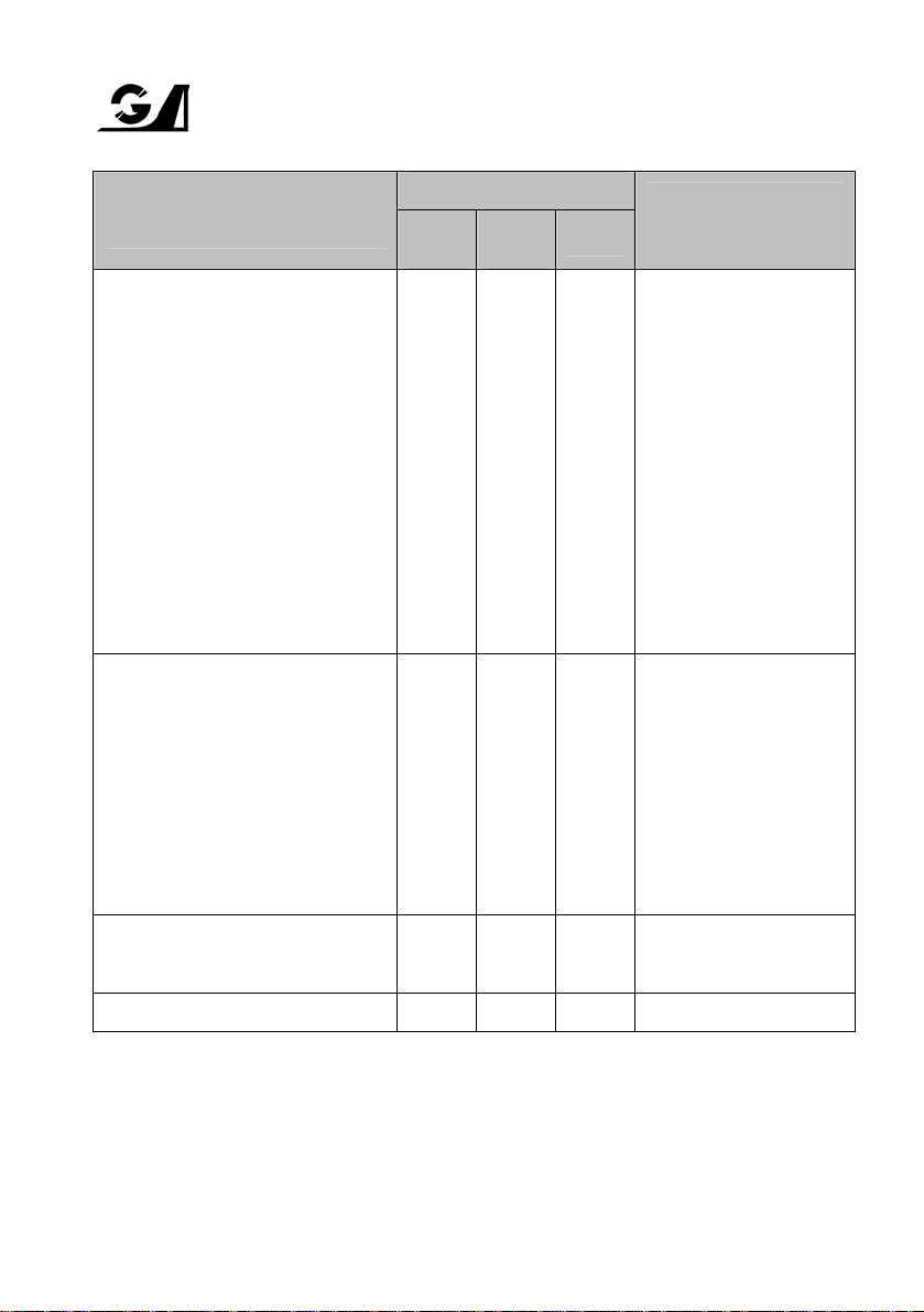
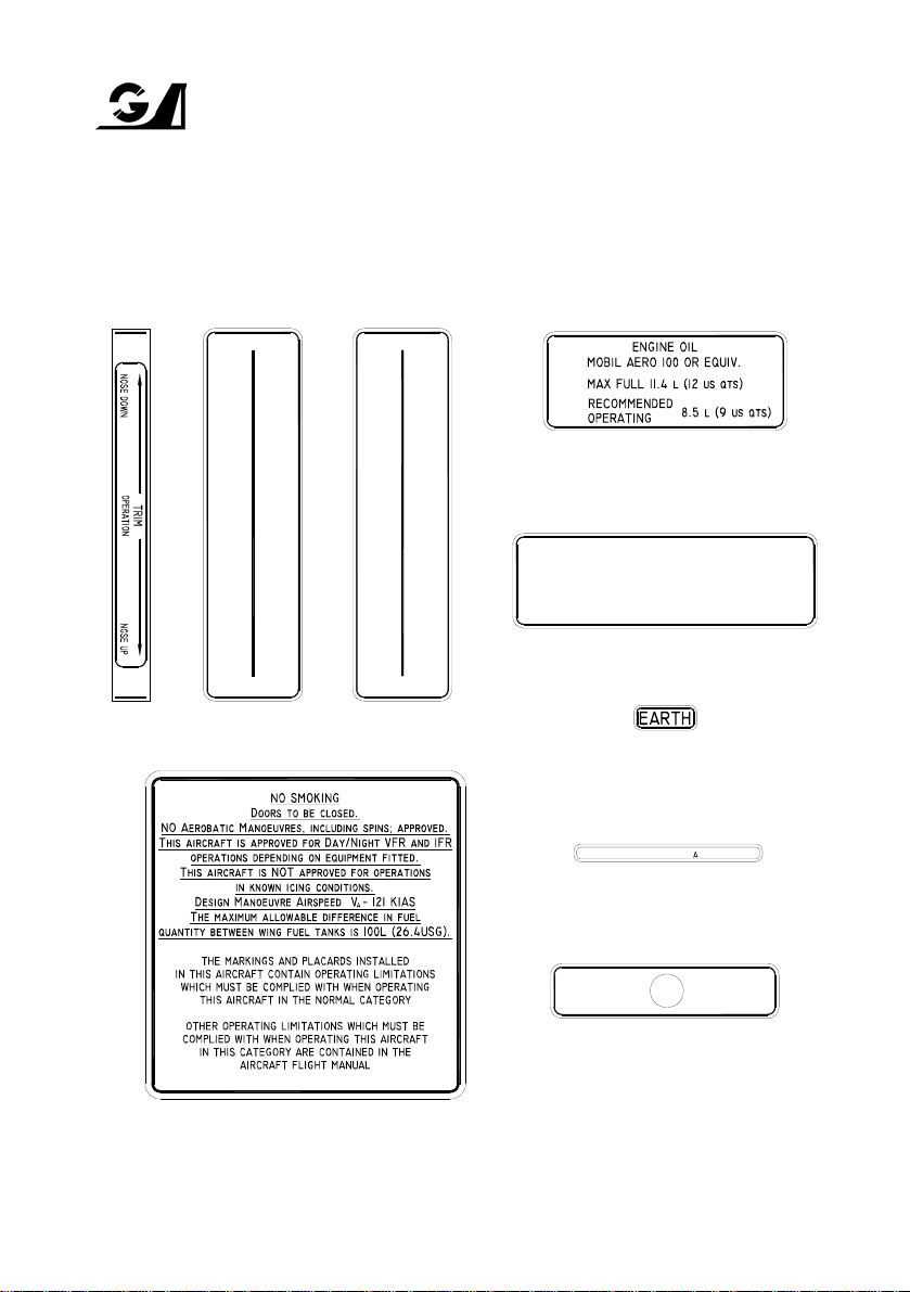
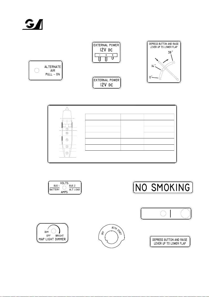
2.15 PLACARDS
The following placards are required, and are to be located in the proximity indicated. Each
placard is to contain wording conforming with the illustrations. The shape and layout of
production items may vary between individual aircraft. Consult the manufacturer for individual
aircraft placard variations.
R
F
O
I
P
N
E
E
N
F
I
I
N
C
E
H
T
H
P
R
I
O
T
T
C
T
H
L
E
C
C
L
O
O
A
S
R
E
S
D
E
Mounted between trim and powerplant controls
M
P
X
I
T
U
C
R
H
C
O
A
L
R
E
S
A
N
E
On underside of oil filler flap
I
T
E
FUEL MIN OCTANE 100/130 OR 100LL
CAPACITY TOTAL: 170l (44.9 usg)
CAPACITY USABLE: 166l (43.9 usg)
Adjacent to wing fuel filler cap on each wing
− AVGAS −
Adjacent to earth
tag on each wing
and cockpit step
MANOEUVRE SPEED V − 121 KIAS
Directly below the Airspeed Indicator
Normal
Static
Source
Located behind alternate static
switch when alternate st atic
switch fitted
Alternate
Static
Source
On top and forward of the engine control levers section
of the centre console
GA-FM-04 Owners and Pilots Information Manual Page 2-11
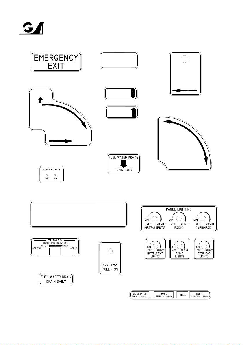
Above each front door
CLOSED
TO OPEN:
PULL HANDLE INWARDS
& ROTATE CLOCKWISE
In the inside of the rear lower corner
of the rear door window frame
GIPPSLAND AERONAUTICS SECTION 2
Model GA8 LIMITATIONS
TO OPEN:
LIFT AND ROTATE
HANDLE BACKWARDS.
Aft of handle on arm rest of
each front door
OPEN
TO OPEN:
PRESS BUTTON &
ROTATE HANDLE.
SLIDE DOOR
FORWARD.
Around release button on the
outside of rear door
OPEN
Behind aft most point of handle
SLIDE DOOR
FORWARD.
OPEN
on the outside/inside of each
front door
OPEN
CLOSED
Beside rear door external handle
Around warning/caution buttons
Just below fuselage belly skin crease
behind right hand front door
STOWAGE OF ARTICLES
UNDER SEATS IS
PROHIBITED
Located on seat backs
Adjacent to trim position indicator
Behind panel lighting dimmer
knobs on the instrument panel
Around park brake knob
on the centre console
Directly behind each fuel drain
cock on the underside of the
fuselage near the right hand fro n t
door and underside of each wing
Page 2-12 Owners and Pilots Information Manual GA-FM-04
(either format)
Mount on electric box cover
GIPPSLAND AERONAUTICS SECTION 2
Model GA8 LIMITATIONS
On the inside of external power flap
Around alternate air knob
on the centre console
0mm (DATUM) 0" (DATUM)
STA 1320mm
STA 1727mm
STA 2210mm
STA 3512mm
STA 4013mm
STA 4623mm
STA 5232mm
AIRCRAFT SECTIONS
On the front face of the cabin baggage shelf near the rear door
Positioned under the Volt/Amps meter
with the switch that changes reading
from Bus 1 and Bus 2 located between
the respective lettering
On the outside of external power flap
GA8 CARGO AND BAGGAGE LOADING
1a − MAIN CARGO AREA
STA 52"
1b − MAIN CARGO AREA
STA 68"
1c − MAIN CARGO AREA
STA 87"
2 − CABIN BAGGAGE SHELF
STA 138"
3 − AFT LUGGAGE BIN
STA 158"
STA 182"
STA 206"
AREA
OBSERVE WEIGHT AND BALANCE LIMITATIONS. SEE FLIGHT MANUAL.
L
R
MAX. LOAD MAX. LOAD INTENSITY
680 KG (1500 LBS)
combined load for
Area 1A, 1B and IC
113 KG (250 LBS)
22 KG (50 LBS)
On centre console beside flap
lever - bottom of placard
facing the pilot's door
470 KG/M² (96 LBS/FT²)
1010 KG/M² (206 LBS/FT²)
250 KG/M² (51 LBS/FT²)
225 KG/M² (46 LBS/FT²)
80 KG/M² (17 LBS/FT²)
Aft face of throttle quadrant
FUEL
PULL − OFF
PUSH
TO
PRIME
Around fuel primer button
Located adjacent to the dimmer
knob on the pilot's side of the
overhead circuit breaker panel
Located behind magneto switch
On the upper side of flap lever
handle near detent button
GA-FM-04 Owners and Pilots Information Manual Page 2-13

GIPPSLAND AERONAUTICS SECTION 2
Model GA8 LIMITATIONS
This page intentionally left blank
Page 2-14 GA8 Airplane Flight Manual GA-FM-04
 Loading...