

Gioco Solutions GSR 36/48V Technical Manual
GSR 36/48V Technical manual
Model 36/48
GSR 36/48V
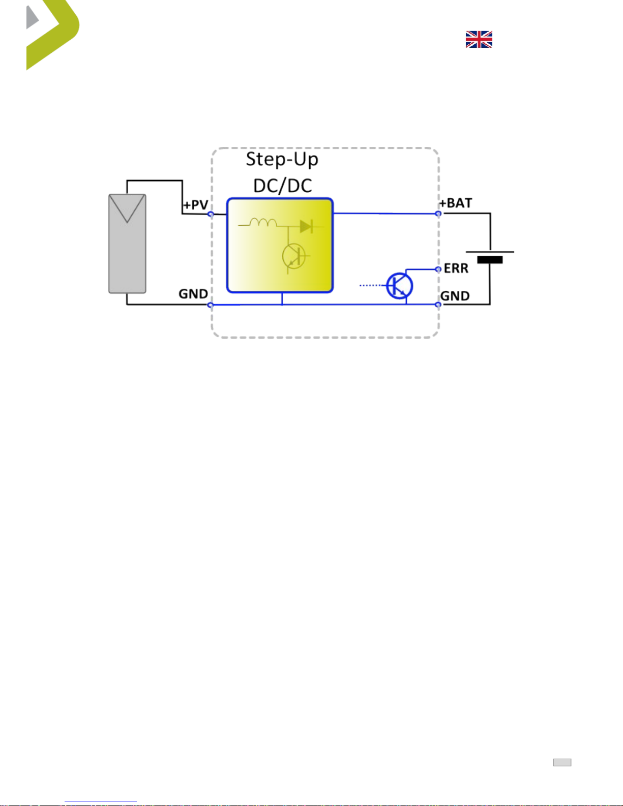
GSR 36/48 is a control circuit for photovoltaic (PV) panels to
battery charge. GSR 36/48 V implement PV panels step up
tension circuit (Step-up) it can so work with PV panels having
a working voltage inferior to the voltage of the battery. In fig. 1
it is possible to find a complete GSR 36/48 V scheme.
The charging circuit of the battery makes the PV module work
in the maximum power point in a voltage range from 2.0V
down to a voltage close to the battery voltage . The battery can
be both 36V and 48V, and the voltage can be changed using a
switch.
The GSR 36/48 can be configured to charge lead-acid batteries
(charge - end voltage, temperature compensated) and lithiumion battery (LiFePo) and in this case applies a constant charge end voltage with temperature.
There is a LOAD terminal that can be used to control the
activation of an external load at the same voltage of the
battery with a maximum current of 5A.
The LOAD terminal can be configured using a dip switch to
fuction for 24 h/day or it can be set to function only at night
(SW3).
The LOAD terminal doesn't function in case of low battery
(voltage lower than the low-battery signal- see Tab 3).
Two LEDs on the GSR 36/48 indicate the operational status of
the system , a green LED indicates the charging current
delivered to the battery , while an amber/red LED indicates a
low battery condition or overtemperature (see Tab.2).
•
MPPT step-up recharge
•
Large tension range on panel
entrance Vp = 2.0V –V
batt
•
Battery tension 36V / 48V with
dipswitch sortable
•
For Pb and Lithium ions batteries
with dipswitch sortable
•
Temperature compensated Charge
voltage
•
Over temperature protection
•
Protection for battery polarity
inversion
•
Case in ABS.
This document is the property of Giocosolutions S.r.l.
1
GSR 36/48V Technical manual
Model 36/48
Working scheme
Fig. 1 working scheme
This document is the property of Giocosolutions S.r.l.
2

GSR 36/48V Technical manual
Model 36/48
Electrical connection and plugging
1 ) Set the DIP switch 1 according to the voltage of the battery in use 36 V or 48 V.
If the GSR 36/48 is powered by an incorrect configuration of the dip switch can ruin the
battery or not function properly.
2 ) Set the DIP switch 2 according to the type of battery (Pb or LiFePo ) as described in the
following table 1 ( configuration dip-switch) . If the GSR 36/48 is powered by an incorrect
configuration of the dip -switch can ruin the battery or not function properly.
3 ) Set the DIP switch 3 according to the type of LOAD expected, 24 h or at night.
4) Install the GSR 36/48 in a dry place , not exposed to rain and adequately ventilated.
During its operation the GSR 36/48 generate more heat and keep warm , to prevent entry
into operation its overtemperature protection you need to keep a clear space around it so
that it can circulate air that helps cooling.
5) Make the electrical connections as shown in Fig. 2,
First of all connect the Load, then the battery and last the PV module. If this sequence is
respected the GSR may signal a battery error( red led stable).
be sure to use the electric cables to the appropriate section of current that must flow . As
soon as the battery is connected both LEDs light up for a second to report good start to
the charge controller.
6 ) Test the installation just connected by verifying that the system charges the battery.
With the PV module exposed to good light , verify that the green LED is flashing, it
indicates that charging current is flowing into the battery. For a closer examination of the
proper functioning of the regulator is recommended to check with a voltmeter while
charging the battery voltage measured at the terminals of the PV module PV + and GND is
close to the maximum output voltage of the photovoltaic module in use ( see the
datasheet module to locate the voltage of maximum power typically referred to as Vmp .
During this test, make sure the battery has a voltage lower than the voltage - end load
set.
This document is the property of Giocosolutions S.r.l.
3
 Loading...