

Ginlong Solis-6K, Solis-10K, Solis-15K, Solis-20K-HV, Solis-6K-LV Installation And Operation Manual
...
PV Grid Tie Inverter
Insta llati on and Opera tion Ma nual
Ver 2. 6
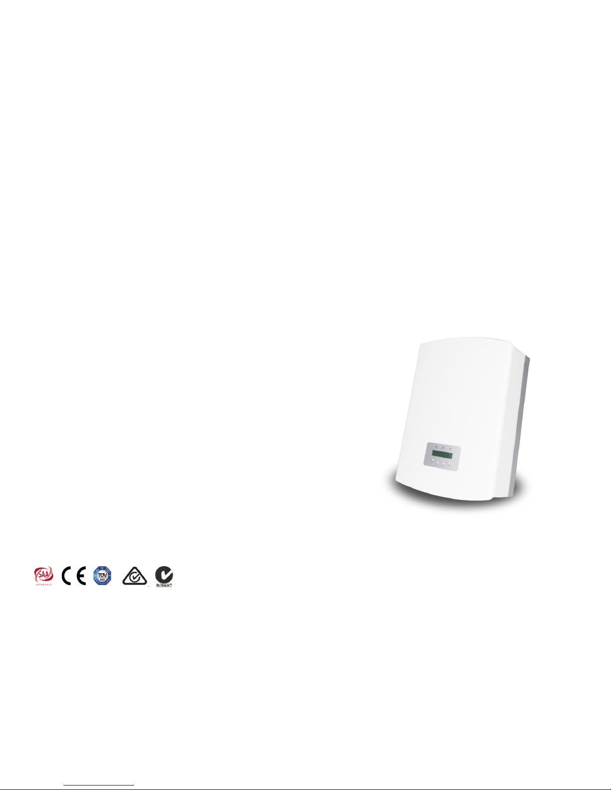
Solis Three Phase Inverter

1. Introduction
2. Safety Instructions
2.1 Safety Symbols
2.2 General Safety Instructions
2.3 Notice For Use
3. Overview
3.1 Front Panel Display
3.2 LED Status Indicator Lights
3.3 Keypad
3.4 LCD
4. Installation
4.1 Selecting Location for the Inverter
4.2 Mounting the Inverter
4.3 Electrical Connections
5. Start and Stop
5.1 Start the Inverter
5.2 Stop the Inverter
Contents
.1.
3
5
5
5
6
7
7
7
8
8
9
9
11
12
18
19
19
………………………
………………………………………
………………………………………………
………………………………
………………………
……………………………………………
…………………………………………………
………………………………………………
…………………
………………………………
……………………………
………………………………………
………………………………
…………………………………
……………………………………………
……………………………………
……………………………………
1.2 Packaging
4
……………………………………
1.1 Introductions
3
……………………………………
Optional
1. Introduction
Sol is thre e phase seri es PV in vert ers c ould t rans fer DC p ower fr om PV pan els int o AC
pow er and fe ed into g rid. Th ere ar e 6 models for S olis t hree p has e inve rter.
Sol is-6K , Solis-10 K, Sol is-1 5K ar e used f or 380 /400 V three p hase gr id system,
Sol is-20 K-HV is used f or 480 V thre e pha se gri d syst em.
Sol is-6K -LV, Solis-10 K-LV ar e use fo r 208/ 220 /240 V thre e phas e grid sy stem.
All 6 m odels a re transfo rmer less t opo logy g rid ti e PV inv erter.
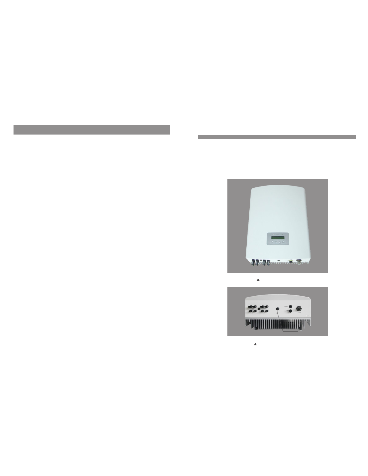
Figure 1.1 Front side view
.3.
Figure 1.2 Bottom side view
6. Operation
6.1 Main Menu
6.2 Information
6.3 Settings
6.3.1 Set Time
6.3.2 Set Address
6.4 Advanced Info.
6.4.1 Alarm Message
Contents
.2.
20
20
20
22
22
22
23
23
…………………………………………………
……………………………………………
……………………………………………
………………………………………………
……………………………………
…………………………………
………………………………………
………………………………
6.4.2 Temperature
6.4.3 Standard No.
6.4.4 Version
6.5 Advanced Settings
6.5.1 Selecting Standard
6.5.2 Grid ON/OFF
7. Maintenance
8. Trouble Shooting
9. Specifications
23
24
24
24
25
27
28
28
30
………………………………………
……………………………………
…………………………………………
…………………………………
……………………………
…………………………………
………………………………………………
…………………………………………
……………………………………………
6.4.5 Communication Data
24
…………………………
6.5.3 Calibrate Energy
27
……………………………
2.Safety Instructions
.5.
2.2 General Safety Instructions
WARNING :
Ele ctric al install atio ns mus t be do ne in ac cord ance w ith the l ocal an d natio nal
ele ctric al safe ty stan dards
CAUTIO N:
CAU TION, R ISK OF EL ECTRI C SHOCK s ymbol i ndica tes imp ortant saf ety
ins truct ions, w hich if not co rrec tly fo llo wed, c ould r esul t in elec tric sh ock.
CAUTIO N:
CAU TION, H OT SURFA CE sym bol i ndic ates s afet y instr uctio ns, whi ch if not
cor rectl y follo wed, could r esul t in bur ns.
NOTE:
NOT E symbo l indic ates im portant sa fety i nstr uct ions , whic h if not c orr ectl y
fol lowed , could r esult in som e dama ge or th e des truc tion o f the in verte r.
2.1 Safety Symbols
Saf ety sym bols us ed in thi s manual, wh ich hi ghli ght p oten tial s afet y risks a nd impo rtant
saf ety inf ormat ion, ar e liste d as follows :
WARNING :
WAR NING s ymbo l ind icat es imp orta nt safe ty inst ructi ons, wh ich if no t
cor rectl y follo wed, could r esul t in ser iou s inju ry or de ath.
Imp roper u se may re sult in pote ntia l elec tri c shoc k haza rds or b urns. T his ma nual
con tains i mportant i nstr ucti ons t hat sh ould b e foll owe d duri ng ins tall ation a nd
mai ntena nce. Pl ease read th ese in stru cti ons ca refu lly be fore us e and kee p them fo r
fut ure ref erenc e.
WARN ING:
Ple ase don ’t connect PV a rray po sitiv e(+) o r negat ive(- ) to the gr ound , it coul d
cau se seri ous da mage to t he inve rter.
.4.
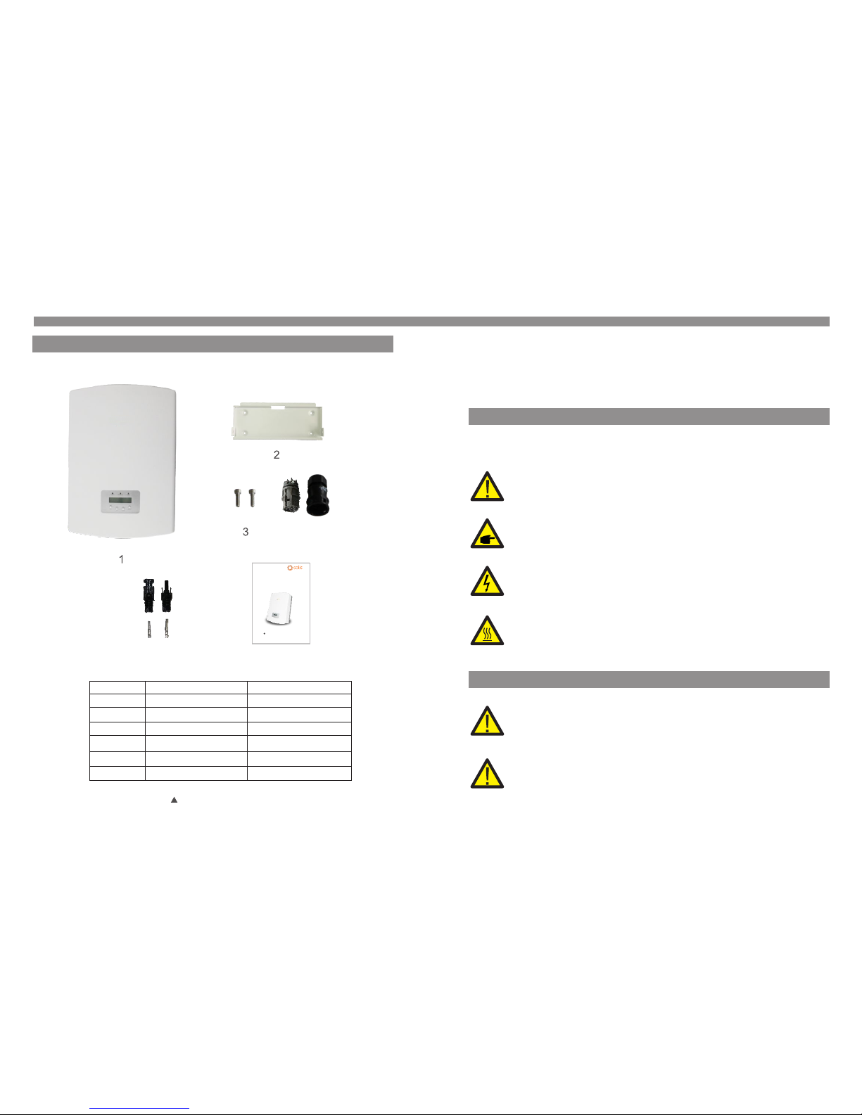
1.2 Packaging
When you receive the inverter, please check if all the parts listed below are included:
1. Introduction
Par t NO.
1
Des cript ion
PV gr id tie in verte r
2
Wal l moun ting b rac ket
3
Loc king sc rews
5
AC con necto r
6
DC co nnect ors
Man ual
7
Num ber
1
1
2
1
4 pai rs(2 fo r Solis -6K)
1
Table 1.1 Material list
4
5
6
PV Grid Tie Inve rter
Installatio n and Ope ratio n Manua l
2014, Ningbo Gin long Tech nolog ies Co. , Ltd.
C
Ver 2.5
Solis Three Phase Inverter
3. Overview
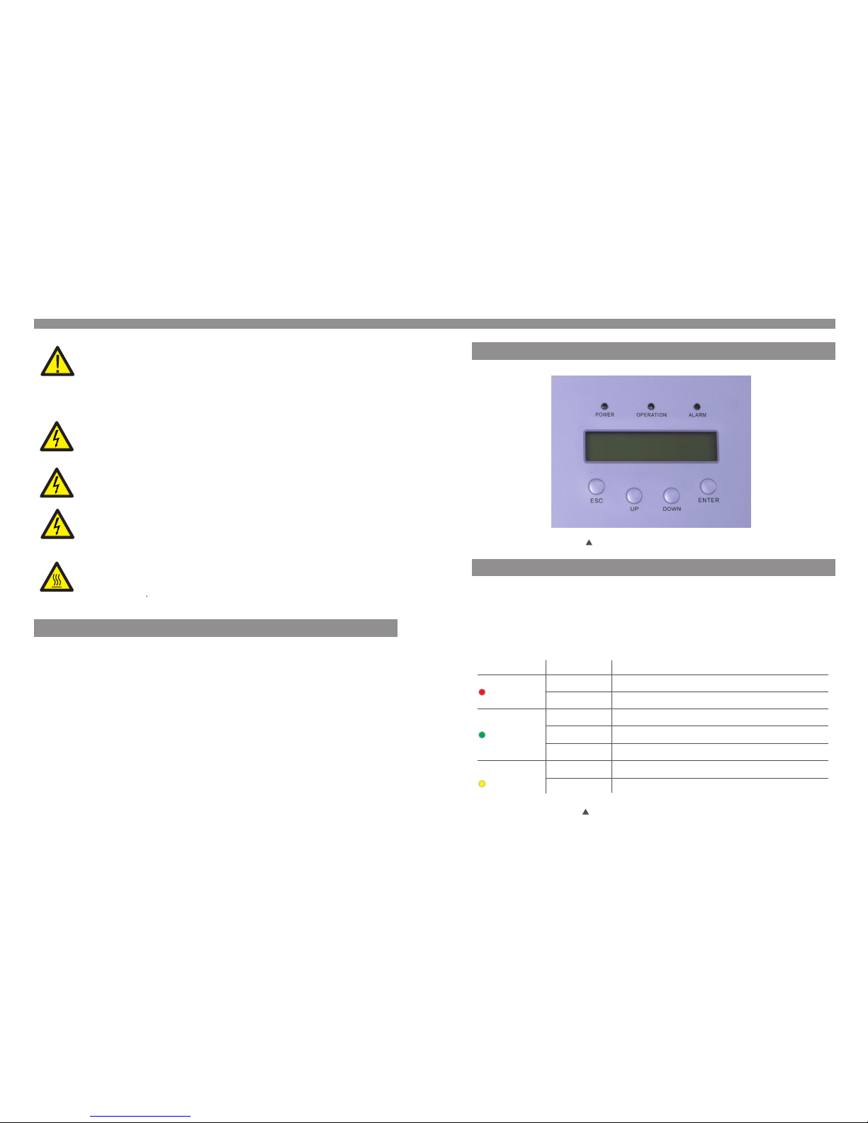
3.1 Front Panel Display
Fig ure 3.1 F ront Pa nel Dis play
3.2 LED Status Indicator Lights
The re are th ree LED s tatus i ndicator l ight s in the f ron t pane l of the i nver ter. Lef t LED:
POW ER LED (r ed) ind icates the p ower s tatu s of th e inve rter. M iddl e LED: OP ERATIO N
LED ( green ) indicate s the op erat ion s tatu s. Rig ht LED : ALA RM LE D (yel low) i ndic ates
the a larm st atus. P lease s ee Tab le 3.1 f or deta ils
Des cript ion
The i nvert er can de tect DC p ower
No DC p ower or l ow DC pow er
The i nvert er is ope ratin g prope rly.
The i nvert er has st opped t o suppl y power.
The i nvert er is ini tiali zing.
Ala rm or fau lt cond ition i s detec ted.
The i nvert er is ope ratin g prope rly.
Sta tus
ON
OFF
ON
OFF
OFF
ON
FLA SHING
Lig ht
POW ER
OPE RATION
ALA RM
Table 3 .1 Stat us Indi cator L ights
2.Safety Instructions
2.3 Notice For Use
The i nvert er has be en constru cted a ccor din g to the a ppli cabl e safet y and tec hnica l
gui delin es. Use the in vert er in in sta llat ions t hat me et the fo llowi ng sepc ifica tion ON LY:
1. Perm anent i nstal latio n is require d.
2. The in verte r must be c onnec ted to a se parat e grounded AC g roup , to whi ch no o ther
ele ctric al equi pment is con nect ed.
3. The el ectri cal ins talla tion must me et all t he app lic able r egul atio ns and st andar ds.
4. The in verte r must be i nstal led acc ording to th e inst ruct ion s stat ed in th is man ual .
5. The in verte r must be i nstal led acc ording to th e corr ect te chn ical s peci fica tions .
6. To start up the in verte r, the Gri d Suppl y Main Sw itch (AC) mu st be sw itch ed on , befo re
the s olar pa nel's DC iso lato r shal l be sw itch ed on. To st op the i nver ter, the G rid S uppl y
Mai n Switc h (AC) mu st be swi tched o ff befo re the s olar pa nel's D C isolator s hall b e
swi tched o ff.
CAUTIO N:
The P V array ( Solar p anels) sup plie s a DC vol tag e when i t is exp osed t o light .
CAUTIO N:
Ris k of elec tric sh ock fro m energy sto red in c apac ito rs of th e Inve rter. D o not
rem ove cov er until 5 min utes a fter d isc onne ctin g all so urces o f suppl y. Se rvic e
tec hnici an only. Warra nty ma y be voi ded i f any un auth oriz ed remo val of co ver.
CAUTIO N:
The s urfac e tempe ratur e of the inver ter ca n reac h up to 7 5℃ (167 F ).
To avoi d risk of burn s, do no t touc h the s urfa ce whe n inve rter is o perat ing.
Inv erter m ust be in stall ed out th e reach of chi ldre n.
WARNING :
To redu ce the ri sk of fire, br anch -cir cui t over -cur rent p rotec tive de vices
(OC PD) are r equir ed for ci rcuits con nect ed to th e Inv erte r.
The r ecomm end rated tr ip cur rent f or AC br eake r shou ld be 25 A for S olis- 6K
inv erter, 3 2A for Sol is-10K, So lis- 15K, S oli s-20 K-HV i nver ter.
CAUTIO N:
Ris k of elec tric sh ock. Do n ot remove co ver. Th ere is n o user s erv icea ble
par ts insi de. Ref er serv icing to qua lifi ed and a ccr edit ed ser vice t echni cian.
.7..6.
4. Installation
4.1 Select a Location for the Inverter
3.3 Keypad
3.4 LCD
The re are fo ur keys i n the fro nt pane l of the In verter(f rom le ft to ri ght ):
ESC , UP, DO WN and E NTE R keys . The ke ypad i s used f or:
Scr ollin g through th e disp laye d opt ions ( the UP a nd DOW N keys );
Acc ess to mo dify th e adjustab le set ting s (th e ESC an d ENTE R keys ).
3. Overview
The t wo-li ne Liqu id Crystal D ispl ay (LC D) is l ocat ed at th e fron t panel o f the Inv erter,
whi ch show s the fol lowing inf orma tion :
Inv erter o perat ion sta tus and data ;
Ser vice me ssages for o pera tor;
Ala rm mess ages and fau lt ind icat ion s.
.8.
.9.
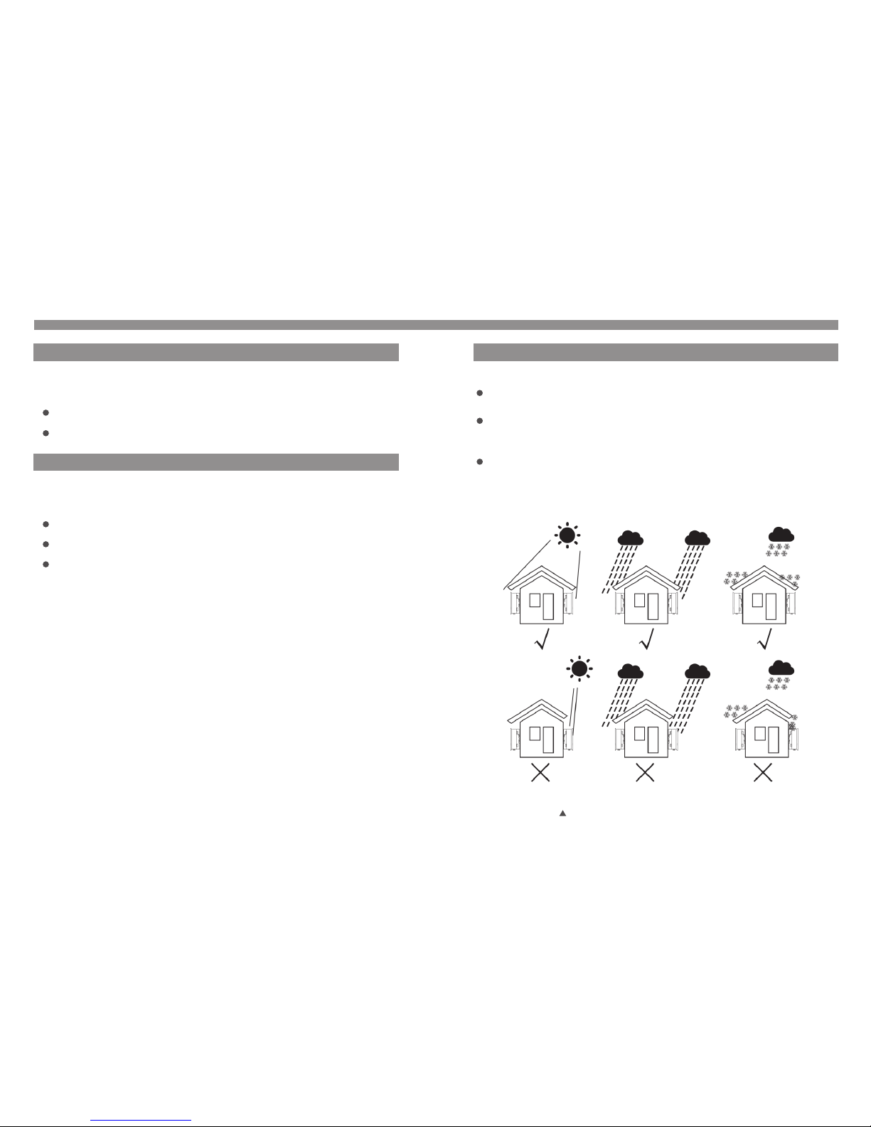
To sele ct a loca tion fo r the invert er, the f ollo win g crit eria s houl d be cons idere d:
To avoi d over heati ng amb ient a ir te mper atur e MUST b e cons idere d when ch oosin g
the i nvert er inst allation l ocat ion. G inl ong re comm end us ing a sun s hade mi nimizing
dir ect sun light when t he amb ient a ir te mper atur e arou nd the un it exce eds 40°C.
Do no t insta ll in sma ll closed sp aces w here a ir cann ot circ ulate f reely. To av oid
ove rheat ing, al ways make su re the f low of a ir ar ound t he inv erte r is not bl ocked .
Exp osure t o direct sun ligh t will i ncr ease t he ope rati onal te mpera ture of t he inverte r and
may c ause ou tput po wer limiti ng. Gi nlon g rec omme nd inv erte r insta lled to a void direc t
sun light o r raini ng.
Fig ure 4.1 R ecomm end Instal lati on pla ce
 Loading...