

Ginlong Solis-2.5K-2G-US, Solis-1K-2G-US, Solis-1.5K-2G-US, Solis-2K-2G-US, Solis-3K-2G-US User's Installation And Operation Manual
...Page 1
2014, Ningbo Ginlong Technologies Co., Ltd.
C
Ningb o Gi nlong Te chn ol ogies C o. , Ltd.
No. 57 Ji nt ong Roa d, B inhai I nd ust ri al Park ,
Xiang sh an, Nin gb o, Zhej ia ng, 3 15 712, P.R. China
Tel: +86 (0 )5 74 6578 1 80 6
Fax: +8 6 (0 )574 65 78 1 606
Email : in fo@gi nl ong.c om
Web : ww w.ginl on g.com
Ple ase rec ord t he se rial nu mber of y our i nve rte r and q uot e thi s whe n you con tact us .
PV Grid Tie Inverter
Inst al la tion and Oper at ion Manual
Solis Single Phase Inverter
Ver 2. 5
-US version
Page 2

1. Introduction
2. Safety Instructions
2.1 Safety Symbols
2.2 General Safety Instructions
2.3 Notice For Use
3. Overview
3.1 Front Panel Display
3.2 LED Status Indicator Lights
3.3 Keypad
3.4 LCD
4. Installation
4.1 Select Location for the Inverter
4.2 Mounting the Inverter
4.3 Electrical Connections
5. Start & Stop
5.1 Start the Inverter
5.2 Stop the Inverter
Contents
.1.
3
5
5
5
6
7
7
7
8
8
9
9
10
11
15
15
15
………………………
………………………………………
………………………………………………
………………………………
………………………
……………………………………………
…………………………………………………
………………………………………………
…………………
…………………………………
……………………………
………………………………………
………………………………
…………………………………
………………………………………………
……………………………………
………………………………………
1.1 Product Descriptions
3
…………………………………
1.2 Packaging
4
…………………………………………
Page 3
1. Introduction
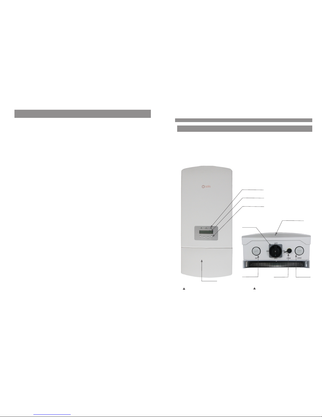
1.1 Pr oduct Des criptions
Figure 1.1 Front side view
.3.
Sol is sing le phas e US seri es inve rters c an tran sfer DC p ower fr om PV pan els int o AC
pow er and fe ed into g rid.
Sol is sing le phas e US seri es inve rters c ontai n 9 model s which a re list ed belo w:
Sol is-1K -2G-U S Solis -1.5K -2G-U S Solis -2K-2 G-US So li s-2 .5K -2G-U S
Sol is-3K -2G-U S Solis -3.6K -2G-U S Solis -4K-2 G-US So li s-4 .6K -2G-U S
Sol is-5K -2G-U S
Figure 1.2 Bottom side view
DC Switch
Water drill hole
DC input
AC input
RS 485
Wiring box
LCD display
4 buttons
LED lights
6. Operation
6.1 Main Menu
6.2 Information
6.3 Settings
6.3.1 Set Time
6.3.2 Set Address
6.4 Advanced Info.
6.4.1 Alarm Message
Contents
.2.
16
16
16
18
18
18
19
19
…………………………………………………
……………………………………………
……………………………………………
………………………………………………
………………………………………
……………………………………
………………………………………
………………………………
6.4.3 Standard No.
6.4.4 Version
6.4.5 Communication Data
6.5 Advanced Settings
6.5.1 Select Standard
6.5.2 Grid ON/OFF
7. Maintenance
8. Trouble Shooting
9. Specifications
20
20
20
21
21
22
24
24
26
……………………………………
…………………………………………
…………………………
…………………………………
………………………………
…………………………………
………………………………………………
…………………………………………
……………………………………………
6.4.2 Temperature
20
……………………………………
6.6 ARC Fault
23
……………………………………………
6.5.3 New Password
6.5.4 Calibrate Energy
23
23
………………………………
…………………………………
Page 4

2.Safety Instructions
2.2 Ge neral Saf ety Instruc tions
WARNIN G:
Ele ctric al inst allat ions mu st be don e in acco rdanc e with th e local a nd nati onal
ele ctric al safe ty stan dards .
.5.
CAUTI ON:
CAU TION, R ISK OF EL ECTRI C SHOCK s ymbol i ndica tes imp ortan t safet y
ins truct ions, w hich if n ot corr ectly f ollow ed, cou ld resu lt in ele ctric s hock.
CAUTI ON:
CAU TION, H OT SURFA CE sy mbol in dicat es safe ty inst ructi ons, wh ich if no t
cor rectl y follo wed, co uld res ult in bu rns.
NOTE:
NOT E symbo l indic ates im porta nt safe ty inst ructi ons, wh ich if no t corre ctly
fol lowed , could r esult i n some da mage or t he dest ructi on of the i nvert er.
2.1 Sa fety Symb ols
Saf ety sym bols us ed in thi s manua l, whic h highl ight po tenti al safe ty risk s and imp ortan t
saf ety inf ormat ion, ar e liste d as foll ows:
WARNIN G:
WAR NIN G sym bol ind icate s impor tant sa fety in struc tions , which i f not
cor rectl y follo wed, co uld res ult in se rious i njury o r death .
Imp roper u se may re sult in p otent ial ele ctric s hock ha zards o r burns . Th is ma nual
con tains i mport ant ins truct ions th at shou ld be fol lowed d uring i nstal latio n and
mai ntena nce. Pl ease re ad thes e instr uctio ns care fully b efore u se and ke ep them f or
fut ure ref erenc e.
WARN ING :
Ple ase d on’t c onn ect P V arra y pos iti ve(+) or ne gat ive (-) to t he gr ound , it co uld
cau se se riou s dam age t o the in ver ter.
1. Introduction
.4.
1.2 Pa ckaging
Par t NO.
1
Des cript ion
PV gr id tie in verte r
2
Wal l mou nti ng brac ket
3
Loc king sc rews
4
Exp ansio n screw s
1
5
3
2
4
Man ual
5
Num ber
1
1
2
4
1
When you receive the inverter, please check if all the parts listed below are included:
Table 1.1 Accessory list
2014, Ningbo Gin long Techn ologi es Co., L td.
C
PV Grid Tie Inve rter
Installatio n and Ope ratio n Manua l
Solis Single Phase Inverter
Ver 2.3
-US version
Page 5
3. Overview
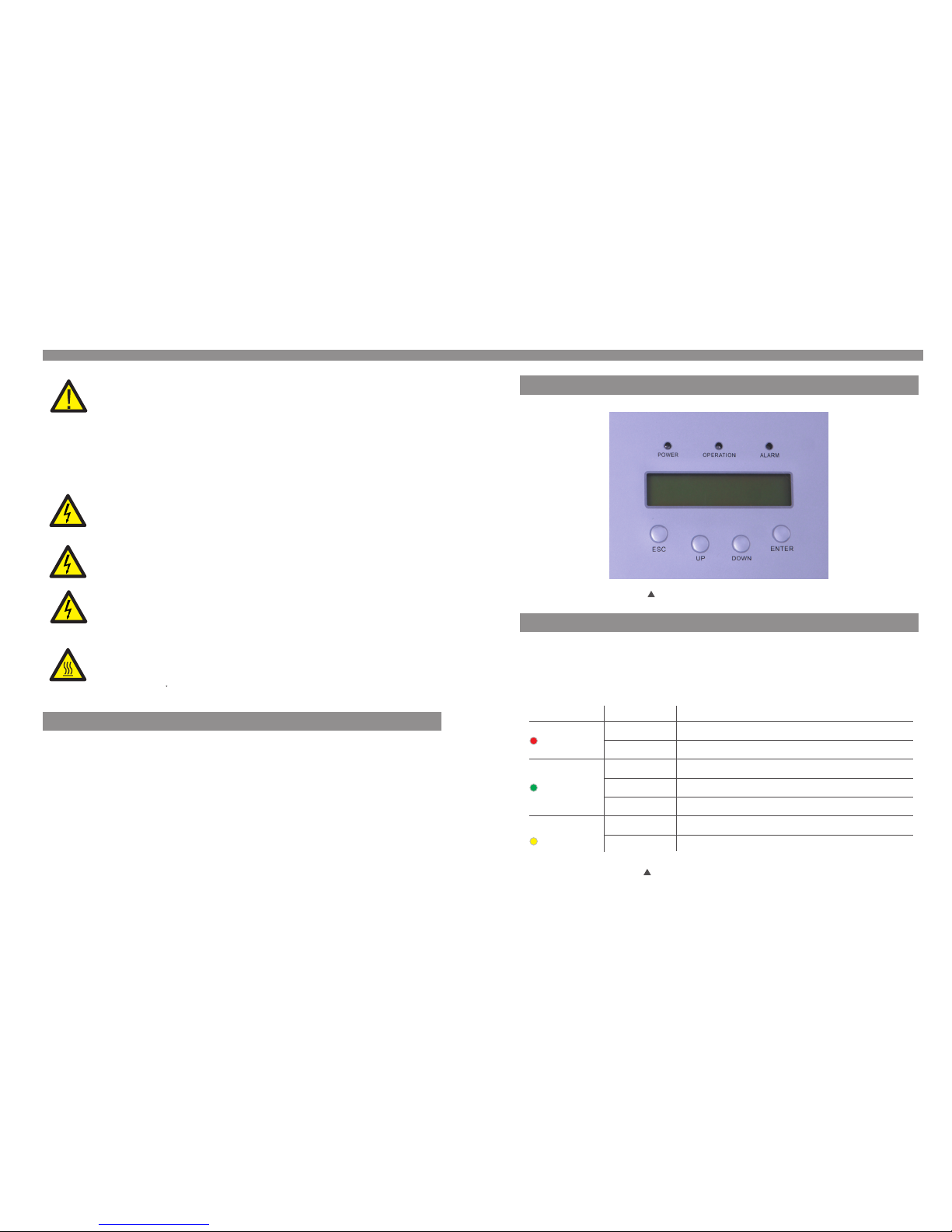
3.1 Fr ont Panel D isplay
Fig ure 3.1 F ront Pa nel Dis play
3.2 LE D Status In dicator Lig hts
The re are th ree LED s tatus i ndica tor lig hts in th e front p anel of t he inve rter. Le ft LED:
POW ER LED (r ed) ind icate s the pow er stat us of the i nvert er. Midd le LED: O PERATI ON
LED ( green ) indic ates th e opera tion st atus. R ight LE D: ALARM L ED (yel low) in dicat es
the a larm st atus. P lease s ee Tab le 3. 1 for det ails
Des cript ion
The i nvert er can de tect DC p ower
No DC p ower or l ow DC pow er
The i nvert er is ope ratin g prope rly.
The i nvert er has st opped t o suppl y power.
The i nvert er is ini tiali zing.
Ala rm or fau lt cond ition i s detec ted.
The i nvert er is ope ratin g prope rly.
Sta tus
ON
OFF
ON
OFF
OFF
ON
FLA SHING
Lig ht
POW ER
OPE RATION
ALA RM
Table 3 .1 Stat us Indi cator L ights
.7.
2.Safety Instructions
2.3 No tice For Us e
The i nvert er has be en cons truct ed acco rding t o the app licab le safe ty and te chnic al
gui delin es. Use t he inve rter in i nstal latio ns that m eet the f ollow ing sep cific ation O NLY:
1. Perm anent i nstal latio n is requ ired.
2. The el ectri cal ins talla tion mu st meet a ll the ap plica ble reg ulati ons and s tanda rds.
3. The in verte r must be i nstal led acc ordin g to the in struc tions s tated i n this ma nual.
4. The in verte r must be i nstal led acc ordin g to the co rrect t echni cal spe cific ation s.
5. To start up the in verte r, the Gri d Suppl y Main Sw itch (A C) must b e switc hed on, b efore
the s olar pa nel's D C isola tor sha ll be swi tched o n. To st op th e inver ter, the G rid Sup ply
Mai n Switc h (AC) mu st be swi tched o ff befo re th e solar p anel' s DC isol ator sh all be
swi tched o ff.
.6.
CAUTI ON:
The P V array ( Solar p anels ) suppl ies a DC vo ltage w hen it is e xpose d to ligh t.
CAUTI ON:
Ris k of elec tric sh ock fro m energ y store d in capa citor s of the In verte r. Do not
rem ove cov er unti l 5 minut es afte r disco nnect ing all s ource s of supp ly. Serv ice
tec hnici an only. Wa rrant y may be vo ided if a ny unau thori zed rem oval of c over.
CAUTI ON:
The s urfac e tempe ratur e of the in verte r can rea ch up to 75℃ ( 167 F).
To avoi d risk of b urns, d o not tou ch the su rface w hen inv erter i s opera ting.
Inv erter m ust be in stall ed out th e reach o f child ren.
WARNIN G:
To redu ce the ri sk of fir e, over -curr ent pro tecti ve devi ces (OC PD) are
req uired f or circ uits co nnect ed to the I nvert er.
The D C OCPD sh ould be i nstal led as lo cal req uirem ent. Al l photo volta ic
sou rce and o utput c ircui t condu ctors s hall ha ve disc onnec ts comp lying w ith
the N EC, Sec tion 69 0, Part I I. All si ngle ph ase inv erter s arein tegra te with D C
swi tch.
The t rip cur rent fo r AC OC PD for 1- 1.5kW m odels s hould b e 10A, fo r 2-2.5 kW
mod els sho uld be 15 A, for 3- 3.6kW s hould b e 20A, fo r 4-5kW s hould b e 25A.
CAUTI ON:
Ris k of elec tric sh ock. Do n ot remo ve cove r. Th ere i s no user s ervic eable
par ts insi de. Ref er serv icing t o quali fied an d accre dited s ervic e techn ician .
Page 6
4. Installation
4.1 Se lect a Loca tion for the In verter
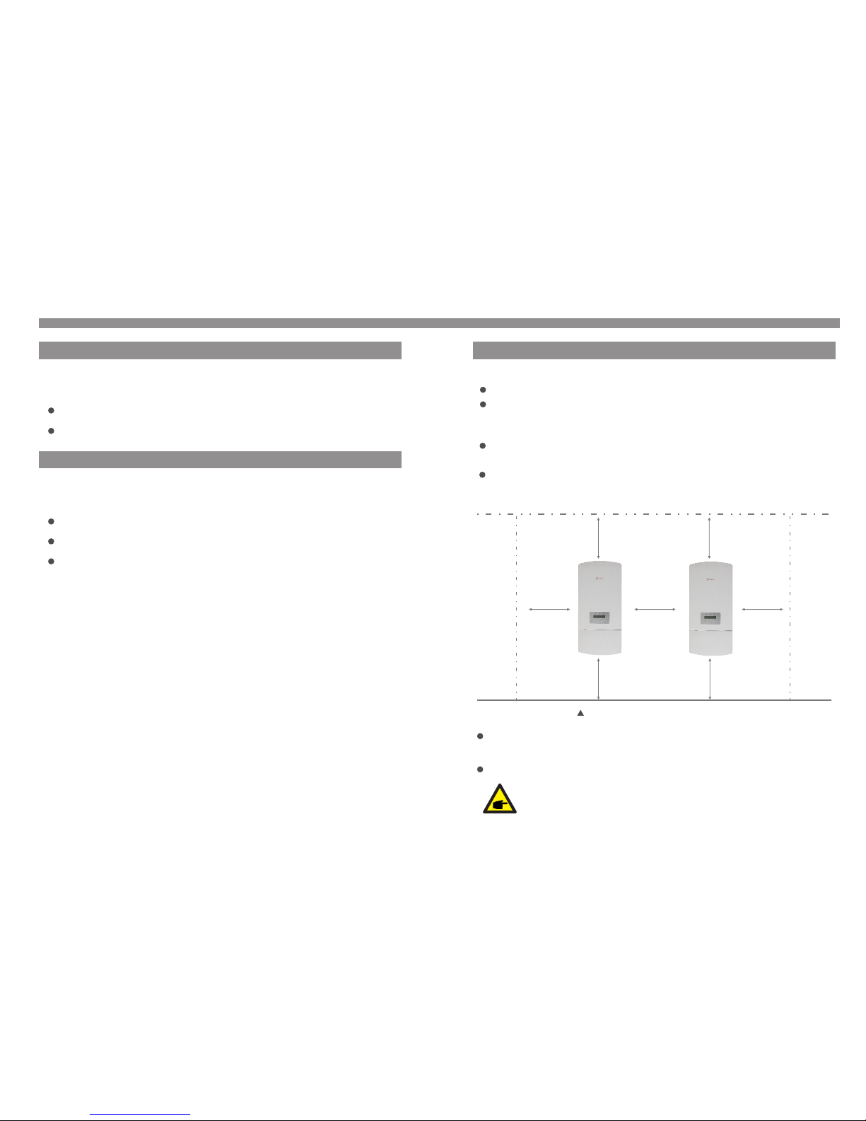
To sele ct a loca tion fo r the inv erter, t he foll owing c riter ia shou ld be con sider ed:
Ins tall on a w all or st rong st ructu re capa ble of be aring t he weig ht.
The i nvert er is des igned t o work in e xtrem e tempe ratur es. The a mbi ent ope ratin g
tem perat ure ran ge is fro m -25℃ to 60℃.
If th ere is mo re than 1 i nvert er inst alled t ogeth er, A min imum 30 0mm cle aranc e
sho uld be ke pt betw een eac h inver ter. The b ott om of the i nvert er shou ld be 500 mm
cle aranc e to the gr ound.
Vis ibi lity of t he LED st atus in dicat or ligh ts and th e LCD loc ated at t he fron t panel o f
the i nvert er shou ld be con sider ed.
Adeq uate ve ntil atio n must be pro vide d if the inv erte r is to be inst alled i n a confin ed spac e.
.9.
NOTE:
Not hing sh ould be s tored o n or plac ed agai nst the i nvert er.
300m m
500m m
500m m
300m m 300m m
300m m
300m m
Fig ure 4.1 I nvert er Moun ting cl earan ce
3.3 Ke ypad
3.4 LC D
The re are fo ur keys i n the fro nt pane l of the In verte r(fro m left to r ight) :
ESC , UP, DO WN an d ENTER k eys. Th e key pad is us ed for:
Scr ollin g throu gh the di splay ed opti ons (th e UP and DO WN ke ys);
Acc ess to mo dify th e adjus table s ettin gs (the E SC and EN TER key s).
3. Overview
The t wo-li ne Liqu id Crys tal Dis play (L CD) is lo cated a t the fro nt pane l of the In verte r,
whi ch show s the fol lowin g infor matio n:
Inv erter o perat ion sta tus and d ata;
Ser vice me ssage s for ope rator ;
Ala rm mess ages an d fault i ndica tions .
.8.
Ins tall ve rtica lly wit h a maxim um incl ine of +/ - 5°.If th e mo unt ed in ve rte r is ti lt ed to a n
ang le grea ter tha n the max imum no ted, he at diss ipati on can be i nhibi ted, an d may res ult
in le ss than e xpect ed outp ut powe r.
Page 7
4.3 El ectrica l Connectio ns
.11.
4. Installation
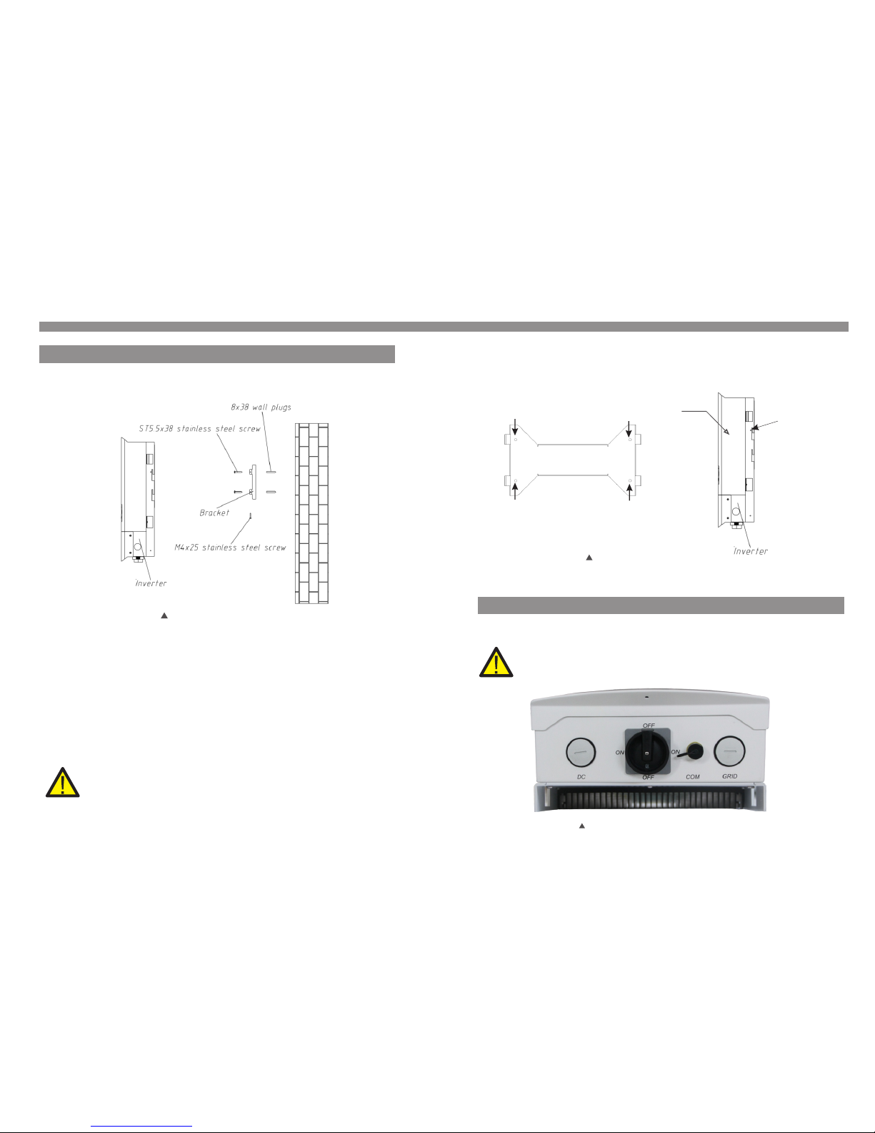
3. Car eful ly han g the inv erte r on the up per part of the wa ll mou nt bracket by f itti ng the
hook s into th e slot of t he bracket . Use M4×25 st ainless st eel sc rews and wash ers
at holes E and F (in Fi gure 4 .2) to se cure t he moun ting hooks t o the rea r of the invert er.
Fig ure 4.3 W all M oun t Brack et
A
B
C
D
Inv erter
E (F)
Bef ore con necti on the wi re, ple ase uns crew th e four sc rews on b oth sid e of wiri ng box,
the n open th e cover.
Fig ure 4.4 B ottom s ide of in verte r
4. Installation
Inv erter s hould b e mount ed in a ver tical p ositi on as sho wn in Fig ure 4.2 . Th e ste ps to
mou nt the in verte r on the wa ll are gi ven as fo llows :
1. Loca te the wa ll stud s in the de sired l ocati on and al ign the w all mou nt brac ket ove r
the s tuds. M ark the m ounti ng hole s. For ma sonry w alls, t he moun ting ho les sho uld be
for a s uitab le dyna bolt ty pe moun ting sy stem.
2. MAKE SU RE BR ACK ET IS ho riz ont al. E nsu re th at the A, B , C, and D m oun tin g hol es
(in F igu re 4.3 ) are a lig ned w ith th e wal l's m ost s ecu re poi nts ( e.g . wal l stu ds in ca se of
cla d bui ldi ng mat eri als ).
.10 .
4.2 Mo unting th e Inverter
Ple ase use s uitab le fixi ngs for w all typ e (e.g. u se dyna bolts f or bric k, maso nry, etc ).
Fig ure 4.2 I nvert er Moun ting
WARNIN G:
Bra cket mu st be mou nted ve rtica lly on a ve rtica l wall su rface .
Ple ase pre ss the co ver of wi ring bo x while l oose th e screw. O therw ise it co uld
bre ak the sc rew thr ead.
Page 8
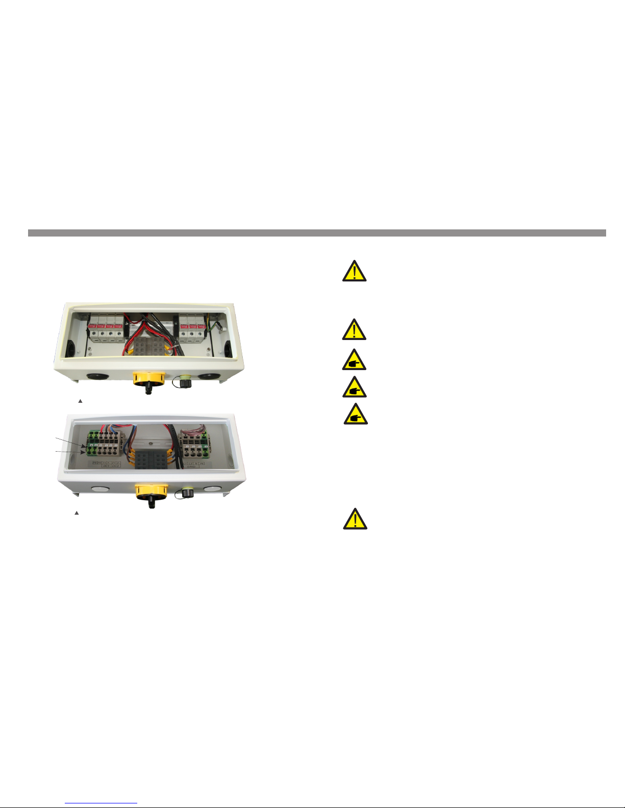
Fig ure 4.5 C onnec tion ar ea of inv erter (Fuse t ype)
DC1+
DC1-
DC2+
DC2-
L1 L 2
N
.13 .
4. Installation
Ple ase ref er figu re 4.5 an d 4.6 to co nnect t he DC1 an d DC2 in th e DC term inal of i nvert er,
the n conne ct the ar ray mou nting b ondin g condu ctor to t wo “PE” t ermin al of DC si de. The
DC wi re conn ected t o DC term inals ( shown i n Figur e 4.5 and 4 .6) is re comme nded
AWG 12- 8. Fo r fuse ty pe inve rter KL M-20 of C ooper B ussma nn or the s ame typ e, only
pro fessi onal ca n repla ce it.
Con nect gr id side o f inver ter:
The i nvert er is sui table f or 208V a nd 240V g rid. Pl ease se e table 4 .1 to con nect ca ble to
inv erter t ermin als. Du e to inve rter mo nitor s volta ge betw een L1 an d L2, Neu tral co uld be
eit her con necte d or not fo r 240V gr id. Gro und mus t be conn ect to th e PE term inal. T he
cab le for gr id conn ectio n to AC term inals ( “L1”, “ L2”, “N ” and “PE ”) is rec ommen ded for
AWG 4 -8. F or fu se type i nvert er, KLM- 30 of Coo per Bus smann o r the sam e type co uld be
use d, only p rofes siona l can rep lace it .
Bef ore ele ctric al conn ectio n Pleas e make su re belo w steps a re stri ctly fo llowe d:
a. Swit ch the Gr id Supp ly Main S witch ( AC) OFF.
b. Swit ch the DC S witch O FF.
.12 .
4. Installation
Term ina l conne ction s:
Bef ore c onne cti on, p lea se mak e sur e the po lar ity o f the ou tpu t vol tage o f PV ar ray
mat che s the“DC +”and “D C-”sy mbols.
Warn ing
Bef ore c onne cti ng in ver ter, pl eas e make sure t he PV ar ray o pen c ircu it vo lta ge is
wit hin t he lim it of t he inv ert er. Oth erw ise t he invert er co uld b e dama ged . The
max imu m allo wab le in put short c irc uit curre nt li mit o f the ph oto vol taic a rra y for ea ch
MPP T inpu t cha nne l is 10A dc fo r the 1- 3.6 kW models a nd it is 15Ad c for the 4-5 kW
mod els .
Ple ase d on’t c onn ect P V arra y pos iti ve or ne gat ive pole to t he gr ound , it co uld
cau se se riou s dam age s to the i nve rte r
Ple ase use q ualif ied DC ca ble for P V syste m.
Fus e type co nnect ion:
Str ip the en d of wire a bout 10 mm, loo se the sc rew on th e termi nal, th en inse rt the wi re
int o the ter minal . Tig ht the sc rews wi th the to rque of 5 Nm.
Non -Fuse t ype con necti on:
Str ip the en d of wire a bout 18 mm. Use a s lotte d screw drive r, inser t to the en d of the
ter minal A and i nsert t he wire i nto the t ermin al B. Loo se the sc rewdr iver, th e cable w ill be
fix ed in the t ermin al.
Fig ure 4.6 C onnec tion ar ea of inv erter (Non- Fuse ty pe)
Termi nal A
Termi nal B
Con nect PV s ide of in verte r:
For f use typ e: Dama ge to the i nvert er thro ugh the u se of fus es as dis conne cting
uni ts in the o utput c ircui t of the in verte r.
WARNIN G:
Dam age to th e DC Disc onnec t due to en large d knock outs.
Enl arged k nocko uts ena ble moi sture t o penet rate th e DC Disc onnec t which
cou ld dama ge elec troni c compo nents i n the DC Di sconn ect.
Note:
Page 9

5. Start & Stop
5.1 St art the Inv erter
To start up the Inverter, it is important that the following steps are strictly followed:
1. Swit ch the gr id supp ly main S witch ( AC) ON fi rst.
2. Swit ch the DC s witch O N. If the v oltag e of PV arr ays are h igher t han sta rt up vol tage,
the i nvert er will t urn on. T he re d LED pow er will l ight, a nd the LC D shows t he comp any's
nam e and the i nvert er mode l.
Sol is-5K -2G-U S
Fig ure 5.1 C ompan y Name an d Inver ter Mod el on LCD
3. When b oth the D C and the AC s ides su pply to t he inve rter, it w ill be re ady to ge nerat e
pow er. Init ially, t he in verte r will ch eck bot h its int ernal p arame ters an d the par amete rs
of th e AC gr id, to en sure th at they a re with in the ac cepta ble lim its. At th e same ti me,
the g reen LE D will fl ash and t he LCD di splay s the inf ormat ion of IN ITIAL IZING .
4. Af ter 3 0-3 00 second s (de pen din g on lo cal r equ ire ment), th e inv ert er wi ll st art to
gen era te po wer. Th e gre en LE D will b e on co nti nua lly a nd the L CD di spl ays
GEN ERATI NG.
WARNIN G:
Do no t touch t he surf ace whe n the inv erter i s opera ting. I t may be
hot a nd caus e burns .
5.2 St op the Inve rter
To stop t he Inve rter, th e follo wing st eps mus t be stri ctly fo llowe d:
1. Swit ch the Su pply Ma in Swit ch (AC) O FF.
2. Wait 30 s eco nds . Swi tch t he DC S wit ch OF F. All the LE Ds of t he in ver ter w ill b e off in o ne
min ute .
Gin long
.15 ..14 .
4. Installation
Inv erter m onito ring Co nnect ion:
The i nvert er can be m onito red by Wi -Fi or GP RS func tions . All t he comm unica tion
fun ction s are opt ional ( Figur e 4.6), p lease r efer to c ommun icati on conn ectio n
ins truct ions.
Fig ure4. 6 Wi-Fi c ommun icati on func tion
Inter ne t
GPR S monit oring
Wi- Fi moni torin g
Sma rt phon e monit oring
PC mo nitor ing
Web s erv er
Rou ter
Wi- Fi moni torin g
Wi- Fi box
Table 4 .1 Grid t ermin al conn ectio n
L1
L2L3
L1
L2
N
208 V~
3PH -△-3W
SPL IT-P HASE
240 V~
L1
L2
N
L1 L2
N
Yes
Yes No
Yes
Yes
Opt ional
Con necti on requ iemen t
TER MINAL
GRI D
STAN DARD
Page 10
6. Operation
V_D C1 350. 8V
I_D C1 5.1A
V_D C2 350. 8V
I_D C2 5.1A
V_G rid 230 .4V
I_G rid 8.1 A
Sta tus: Ge nerat ing
Pow er: 148 8W
Gri d Frequ ency
F_G rid 60. 06Hz
Total E nergy
025 8458 kw h
Thi s Month : 0123k wh
Las t Month : 0123k wh
Today : 15.1k wh
Yeste rday: 1 3.5kw h
10 se c
10 se c
10 se c
10 se c
10 se c
10 se c
10 se c
10 se c
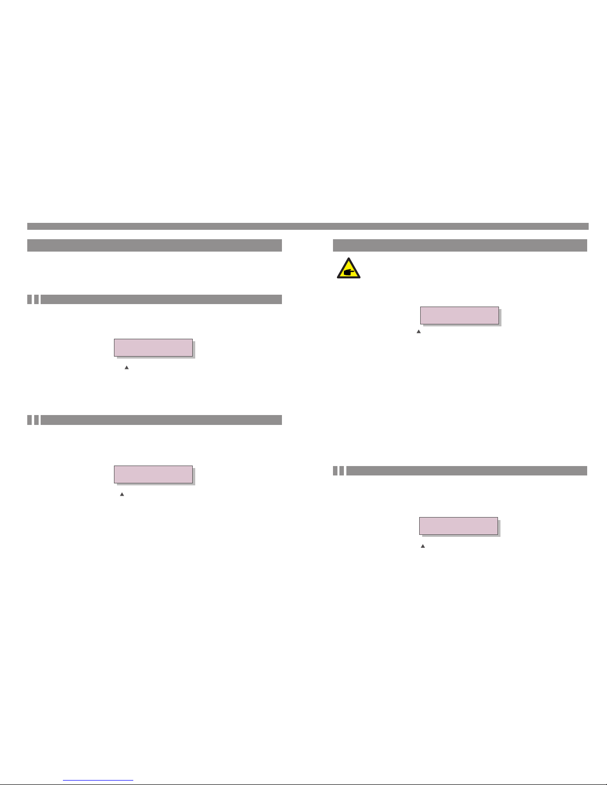
V_D C1: Sho ws inpu t 01 volt age val ue.
I_D C1: Sho ws inpu t 01 curr ent val ue.
V_D C2: Sho ws inpu t 02 volt age val ue.
I_D C2: Sho ws inpu t 02 curr ent val ue.
V_G rid: Sh ows the g rid's v oltag e value
I_G rid: Sh ows the g rid's c urren t value .
Status: Shows instant status of the Inverter.
Power: Shows instant output power value.
F_G rid: Sh ows the g rid's f reque ncy val ue.
Total g enera ted ene rgy val ue
Thi s Month : Tota l ene rgy gen erate d this mo nth.
Las t Month : Tota l ene rgy gen erate d last mo nth.
Today : Tota l ene rgy gen erate d today.
Yest erd ay: Tot al ener gy ge ne rat ed ye st erd ay.
Dis play
Dur ation
Des cript ion
Table 6 .1 Info rmati on list
Pre ssing t he ESC ke y retur ns to the M ain Men u. Pres sing th e ENTER k ey lock s
(Fi gure 6. 2(a)) o r unloc ks (Fig ure 6.2 ( b)) the s creen .
5.2 St op the Inve rter
Fig ure 6.2 L ocks an d Unloc ks the Sc reen of L CD
(b)(a)
.17 ..16 .
6. Operation
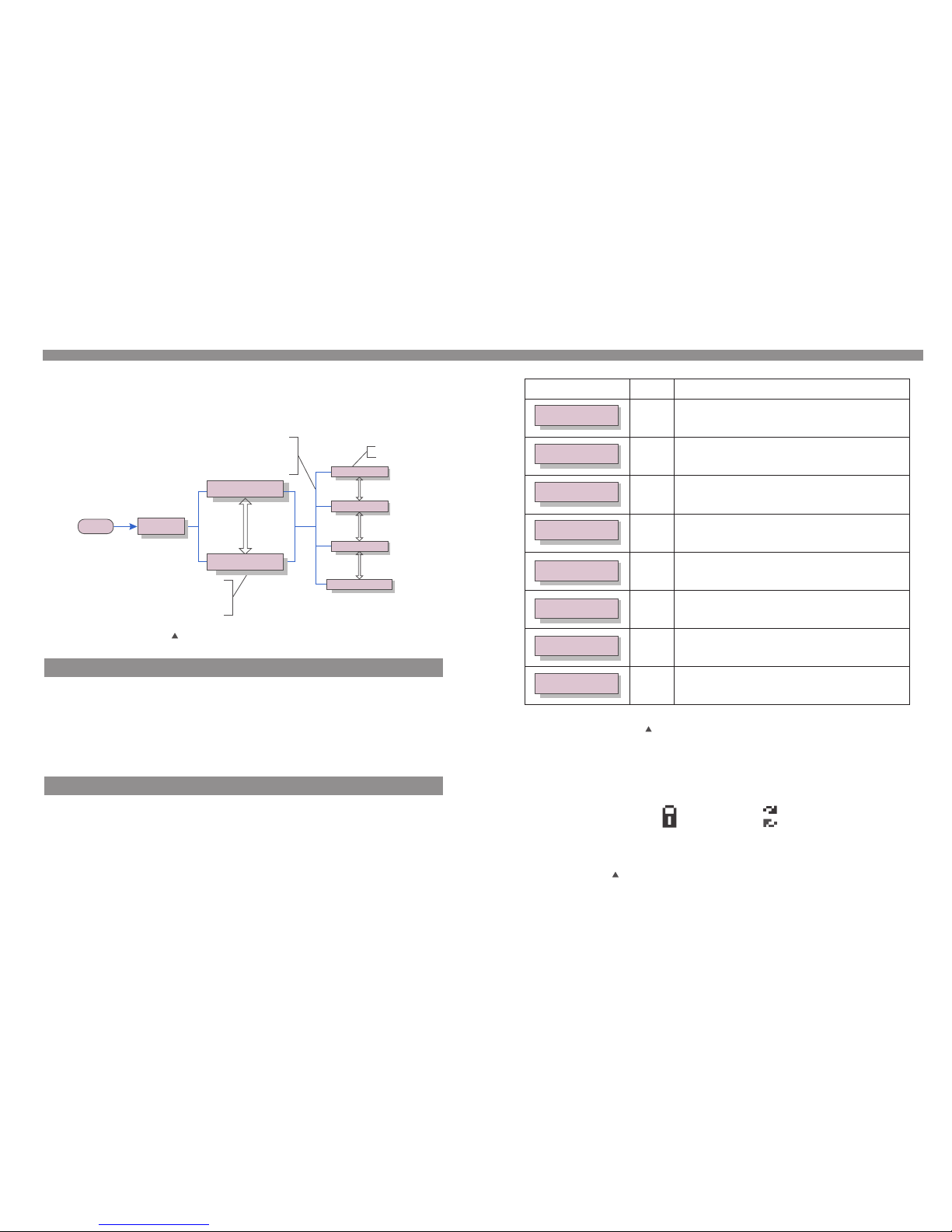
6.1 Ma in Menu
Dur ing nor mal ope ratio n, the di splay a ltern ately s hows th e power a nd the op erati on
sta tus wit h each sc reen la sting f or 10 sec onds (s ee Figu re 6.1) . Scree ns can al so be
scr olled m anual ly by pre ssing t he UP and D OWN k eys. Pr ess the E NTER ke y to
acc ess to th e Main Me nu.
Fig ure 6.1 O perat ion Ove rview
5 sec
Manufacturer
Model name
Sta rt
Pow er 3424 W
01- 01-20 14 12:0 4
Sta tus: Ge nerat ing
01- 01-20 14 12:0 4
Inf ormat ion
Set tings
Adv anced I nfo.
Adv anced s ettin gs
UP/ DOWN
UP/ DOWN
UP/ DOWN
UP/ DOWN or
aut o-scr oll
(10 s ec)
Pre ssing t he
ENT ER key
giv es acce ss to
the m ain men u.
Pre ssing t he
ESC k ey
cal ls back t he
pre vious m enu.
Mai n Menu
The re are fo ur subm enus in t he Main M enu (se e Figur e 6.1):
1. Info rmati on
2. Sett ings
3. Advan ced Inf o.
4. Advan ced Set tings
6.2 In formati on
The S olis Si ngle Ph ase Inv erter m ain men u provi des acc ess to op erati onal da ta and
inf ormat ion. Th e inf ormat ion is di splay ed by sel ectin g "Info rmati on" fro m the men u
and t hen by sc rolli ng up or do wn.
Page 11
6. Operation
.19 .
6.4 Adv anced Inf o - Techni cians Onl y
Aft er ente r the cor rect pa sswor d the Mai n Menu wi ll disp lay a scr een and b e able to a ccess
to th e follo wing in forma tion.
1. Alar m Messa ge
2. Temper ature
3. Stan dard No .
4. Versi on
5. Comm unica tion Da ta
The s creen c an be scr olled m anual ly by pre ssing t he UP/D OWN key s. Pres sing th e ENTER
key g ives ac cess to a s ubmen u. Pres s the ESC k ey to ret urn to th e Main Me nu.
6.4.1 Alarm Me ss ag e
The d ispla y shows t he 10 lat est ala rm mess ages (s ee Figu re 6.6) . Scree ns can be s croll ed
man ually b y press ing the U P/ DOWN k eys. Pr ess the E SC key to r eturn t o the pre vious
men u.
Ala rm0: OV- G-V
Tim e: 27 -11 Da ta: 7 171
Fig ure 6.6 Al arm Mes sage
NOTE:
To access t o thi s ar ea is f or f ull y qu ali fi ed an d ac cre di ted t echni cians o nly.
Pleas e ent er t he pa ss wor d to “ Adv anced I nfo .” and “A dva nc ed se tti ng ”
YES =<ENT > NO=<E SC>
Pas sword :0000
Fig ure 6.5 E nter pa sswor d
Sel ect “Ad vance d Info. ” from th e Main Me nu. The s cre en will r equir e the pas sword a s below
The d efaul t passw ord is “0 010". P lease p ress “d own” to m ove the c ursor, p ress “u p” to
sel ect the n umber.
.18 .
6.3 Se ttings
The f ollow ing sub menus a re disp layed w hen the S ettin gs menu i s selec ted:
1. Set Tim e
2. Set Add ress
6.3.1 Set Time
Thi s funct ion all ows tim e and dat e setti ng. Whe n this fu nctio n is sele cted, t he LCD wi ll
dis play a sc reen as s hown in F igure 6 .3.
NEX T=<EN T> OK=< ESC>
01- 01-20 10 16:3 7
Fig ure 6.3 S et Time
Pre ss the UP /DOWN k eys to se t time an d data. P ress th e ENTER k ey to mov e from on e
dig it to the n ext (fr om left t o right ). Pres s the ESC k ey to sav e the set tings a nd retu rn to
the p revio us menu .
6.3.2 Set Addr es s
YES =<ENT > NO=<E SC>
Set Ad dress : 02
Fig ure 6.4 S et Addre ss
Pre ss the UP /DOWN k eys to se t the add ress. P ress th e ENTER k ey to sav e the set ti ngs .
Pre ss the ES C key to ca ncel th e chang e and ret urn to th e previ ous men u.
6. Operation
Thi s funct ion is us ed to set t he addr ess whe n the inv erter i s conne cted to t he PC. Th e
add ress nu mber ca n be assi gned fr om “01” to “99” (see Fi gure 6. 4). The d efa ult add ress
num ber of So lis Sin gle Pha se Inve rter is “ 01”.
Page 12

6. Operation
.21 .
Thi s funct ion is us ed to sel ect the g rid's r efere nce sta ndard ( see Fig ure 6.11 ).
YES =<ENT > NO=<E SC>
Sta ndard :UL-2 40V-A
Fig ure 6.11
NOTE:
This fu nct io n is fo r te chn ic ian s us e onl y.
NOTE:
Befor e to us in g thi s fu nct io n, pl ea se se t "G RID O FF " to st op inve rter (r efe r
to Sect ion 6 .5 .2) .
Pre ss th e UP/ DOW N keys t o sel ect t he sta nda rd (A S47 77, V DE4 105 , VDE0 126 , UL- 240 V-A,
UL- 208 V-A, U L-2 40V, UL- 208 V, MEX- CFE , G83 /2 (f or 1-3 .6k W mod els ), G5 9/3 ( for 4- 5kW
mod els ), EN 504 38 DK, EN50 438 I E, EN 504 38 NL an d “Use r-D ef” f unc tio n). P res s the
ENT ER ke y to con fir m the s ett ing . Pre ss the E SC ke y to ca ncel chan ges a nd re tur ns to
pre vio us me nu.
NOTE:
The def aul t se tti ng i s 240 V sp lit p ha se “U L- 240 V” o r “UL -240V- A”, if it ’s
diffe ren t pleas e selec t 208V si ngl e ph ase “ UL -20 8V ” or “U L- 208 V-A ” or
220V sp lit p ha se “M EX -CF E” . Oth er s tan da rds a re f or 50 Hz grid , pleas e
don’t s ele ct .
6.5.1 Selec ti ng S ta nd ard
6.5 Adv anced Set tings - Technicia ns Only
Sel ect Adva nced Se tting s from th e Main Me nu to acc ess the f ollow ing opt ions:
1. Sele ct Stan dard 2. Gri d ON/OF F
3.N ew Pass word 4. Calib rate En ergy
NOTE:
To access t o thi s ar ea is f or f ull y qu ali fi ed an d ac cre di ted t echni cians o nly.
Pleas e fol lo w 6.4 t o en ter p as swo rd t o acc es s thi s me nu.
6.4.2 Tempe ra tu re
The s creen s hows th e tempe ratur e insid e the inv erter ( see Fig ure 6.7 ).
Fig ure 6.7 Tem per ature i nside t he Inve rter
Tempe ratur e
046 .6
℃
6. Operation
6.4.3 Stand ar d No .
The s creen s hows th e refer ence st andar d of the In verte r (see Fi gure 6. 8).
Sta ndard : UL-24 0V-A
Fig ure 6.8 E xampl e of Stan dard of t he Inve rter
6.4.4 Versio n
The s creen s hows th e model v ersio n and the s oftwa re vers ion of th e Inver ter
(se e Figur e 6.9).
Mod el: 08
Sof tware Ve rsion : D2000 1
Fig ure 6.9 M odel Ver sion an d Softw are Vers ion
6.4.5 Commu ni ca ti on D ata
The s creen s hows th e inter nal dat a of the In verte r (see Fi gure 6. 10), wh ich is fo r servi ce
tec hnici ans onl y.
01- 05: 01 25 E 4 9D AA
06- 10: C2 B5 E 4 9D 55
Fig ure 6.1 0 Commu nicat ion Dat a
.20 .
The re ar e 4 sett ing s for U SA and CS A mark et, U L-2 40V a nd UL- 208 V are t he se tti ngs fo r
inv ert er wi tho ut AFCI m odu le, U L-2 40V- A and UL- 208 V-A are th e set tin gs fo r inverte r
int egr ate w ith AFC I mod ule .
Page 13

.23 .
6. Operation
.22 .
Sel ectin g the “Us er-De f” menu w ill acc ess to th e follo wing su bmenu ( see Fig ure 6.1 2),
Fig ure 6.1 2
Pres s the UP/DO WN keys to scr oll thro ugh item s. Pres s the ENTER ke y to edit the
high light ed item. Pr ess the UP/ DOWN key s again to ch ange the se tting . Press the EN TER
key to sav e the setti ng. Pres s the ESC key to ca ncel cha nges and re turns to th e previ ous
menu .
OV-V : 262 V
UN- V: 210V
OV-V : 240 --- 270V
UN- V: 180- --2 10V
OV-G -F: 60. 3—62.0H z(50. 3---5 2.0Hz )
UN- G-F: 57 .0—59.5 Hz(47 .0--- 49.5H z)
Bel ow is the s ettin g range f or “Use r-Def ”. Usin g this fu nctio n, the li mits ca n be chan ged
man ually.
6.5.2 Grid ON /O FF
Thi s funct ion is us ed to sta rt up or st op the po wer gen erati on of Sol is Sing le Phas e
Inv erter ( see Fig ure 6.1 3).
Gri d ON
Gri d OFF
Fig ure 6.1 3 Set Gri d ON/OF F
Scr eens ca n be scro lled ma nuall y by pres sing th e UP/DO WN keys . Press t he ENTE R key
to sa ve the se tting . Press t he ESC ke y to retu rn to the p revio us menu .
6.5.3 Clear in g En er gy
NOTE:
Pleas e, se t "G rid O N" t o sta rt u p the i nv ert er a fte r the set tings ( refer t o
Secti on 6. 5. 2). O th erw is e the i nv ert er w on' t st art u p.
NOTE:
The " Use r-D ef " fun ct ion c an b e onl y us ed by t he s erv ic e eng ineer a nd
must be a llo we d by th e lo cal e ne rgy s up pli er.
6.6 Arc f ault(fo r AFCI version )
Sol is Sing le Phas e Inver ter can i ntegr ate wit h AFC I modul e which c an dete ct the ar c in DC
cir cuit. I f arc fau lt happ en, it ca n only be r emove d manua lly.
Dur ing sta rt up inv erter w ill che ck AFCI mo dule. I f the che ck is OK, i nvert er will s tart
nor mally. I f the c heck is f ail, LC D will sh ow belo w:
Fig ure 6.1 6 AFC I check f ail
AFCI C heck Fa il
Res tart< ESC>
Pre ss <ESC > for 3 sec onds, t he inve rter wi ll rest art. If t he faul t happe n again , pleas e turn
off i nve rter to r estar t. If the f ault st ill hap pen, pl ease co ntact u s.
Thi s funct ion is us ed to set t he new pa sswor d for men u “Adva nced in fo.” an d “Adva nced
inf ormat ion” (s ee Figu re 6.14 ).
Mai ntena nce or re place ment co uld cle ar or cau se a diff ere nt valu e of tota l energ y. Us e thi s
fun ction c ould al low use r to revi se the va lue of to tal ene rgy to th e same va lue as be fore. I f
the m onito ring we bsite i s used th e data wi ll be syn chron ous wit h this se tting a utoma tical ly.
(se e Figur e 6.15) .
Pre ss the DO WN key to m ove the c ursor, P ress th e UP key to r evi se the va lue. Pr ess the
ENT ER key to e xecut e the set ting. P ress th e ESC key t o retur n to the pr ev iou s men u.
Ent er the ri ght pas sword b efore s et new pa sswor d. Pres s the DOW N key to mo ve the
cur sor, Pre ss the UP k ey to r evise t he valu e. Pres s the ENT ER key to e xecut e the set ting.
Pre ss the ES C key to re turn to t he prev ious me nu.
6.5.3 New Pas sw or d
6.5.4 Calib ra te E ne rg y
Fig ure 6.1 4 Set new p asswo rd
Fig ure 6.1 5 Calib rate en ergy
YES =<ENT > NO=<E SC>
Pas sword : 0000
YES =<ENT > NO=<E SC>
Ene rgy:0 00000 0kWh
6. Operation
Page 14

8. Trouble Shooting
NOTE:
If the in ver te r dis pl ays a ny a lar m me ssa ge a s lis te d in Tabl e 8.1 ; pl eas e
turn of f the i nvert er (ref er to S ec tio n 5. 2 to st op y our i nv ert er ) and w ai t for 5
minut es be fo re re st art in g it (r ef er to S ec tio n 5. 1 to st art you r inver ter ). I f the
failu re pe rs ist s, p lea se c ont ac t you r lo cal d is tri butor o r the ser vice ce nte r.
Pleas e kee p re ady w it h you t he f oll ow ing i nf orm at ion b efore c ontac ting us .
1. Seri al number o f Sol is Si ngl e Pha se In ver ter;
2. The dis tri but or/ dea ler o f Sol is Single P has e Inv ert er (i f ava ila ble );
3. Inst all ati on dat e.
4. The des cri pti on of p rob lem ( i.e. the al arm m ess age d isp lay ed on th e LCD a nd th e sta tus
of th e LED statu s ind ica tor l igh ts. O the r rea din gs obt ain ed fr om th e Inf orm ati on su bme nu
(re fer t o Sec tio n 6.2) w ill a lso b e hel pfu l.) ;
5. Th e PV arr ay co nfi gur ati on (e .g. n umb er of pa nel s, ca pac ity o f pan els , numb er of s tri ngs
, etc .);
6. Your c ont act de tai ls.
.25 ..24 .
8. Trouble Shooting
The i nve rte r is de signed in a cco rda nce w ith t he mo st imp ort ant i nte rna tio nal g rid -ti ed
sta nda rds a nd sa fet y and el ect rom agn eti c com pat ibi lit y req uir eme nts . Befo re de liv eri ng to
the c ust ome r, the in ver ter h as be en su bje cte d to sev era l tes ts to e nsu re it s opti mal o per ati on
and r eli abi lit y.
In ca se of fai lure, t he LCD sc reen wi ll disp lay an al arm mes sage. I n this ca se, the i nvert er
may s top fee ding in to the gr id. The f ail ure des cript ions an d their c orres pondi ng alar m
mes sages a re list ed in Table 8 .1:
Ala rm Mess age
OV-G -V
UN- G-V
OV-G -F
UN- G-F
G-I MP
NO- GRID
OV-D C
OV-B US
UN- BUS
GRI D-INT F.
INI -FAULT
OV-T EM
GRO UND-FA ULT
Fai lure de scrip tion
Ove r grid vo ltage
Und er grid v oltag e
Ove r grid fr equen cy
Und er grid f reque ncy
Hig h grid im pedan ce
No gr id volt age
Ove r DC volt age
Ove r DC bus vo ltage
Und er DC bus v oltag e
Gri d inter feren ce
Ini tiali zatio n syste m fault
Ove r Temp eratu re
Gro und fau lt
Table 8 .1 Faul t messa ge and de scrip tion
ILe ak-FAU LT
Rel ay-FAU LT
DCi nj-FAU LT
Hig h Grid le akage c urren t
Rel ay chec k fault
Hig h DC inje ction c urren t
AFC I Check FA ULT
ARC -FAULT
AFC I modul e self ch eck fau lt
ARC d etect ed in DC ci rcuit
Sol is Sing le Phas e Inver ter doe s not req uire an y regul ar main tenan ce. How ever, cl eanin g
the d ust on he at-si nk will h elp the i nvert er to dis sipat e the hea t and inc rease i ts life t ime.
The d ust can b e remov ed with a s oft bru sh.
CAUT ION:
Do not to uch th e inver ter' s surfa ce whe n it is oper atin g. Some p arts of th e inve rter
may be ho t and cau se burn s. Turn off t he inve rter (r efer t o Secti on 5.2) a nd wait f or
a cool -dow n perio d befor e befo re any ma intenance o r clean ing op eration.
The L CD and t he LED s tat us ind ica tor li ght s can be c lean ed wi th a dam p clot h if they are t oo
dir ty to be r ead.
NOT E:
Nev er use any sol vent s, abr asi ves or c orro siv e mate rial s to cle an the i nverter.
7. Maintenance
Fig ure 6.1 7 Arc f ault
ARC- Fault
Res tart< ESC>
Ple ase che ck DC cab les and c onnec tions t o ident ify the s ource o f possi ble arc ing. Th en
pre ss <ESC > for 3 sec onds, t he inve rter wi ll rest art.
Dur ing nor mal ope ratio n, If arc f ault ha ppen in D C circu it, the i nvert er will s top out put and
LCD show be low:
6. Operation
Page 15
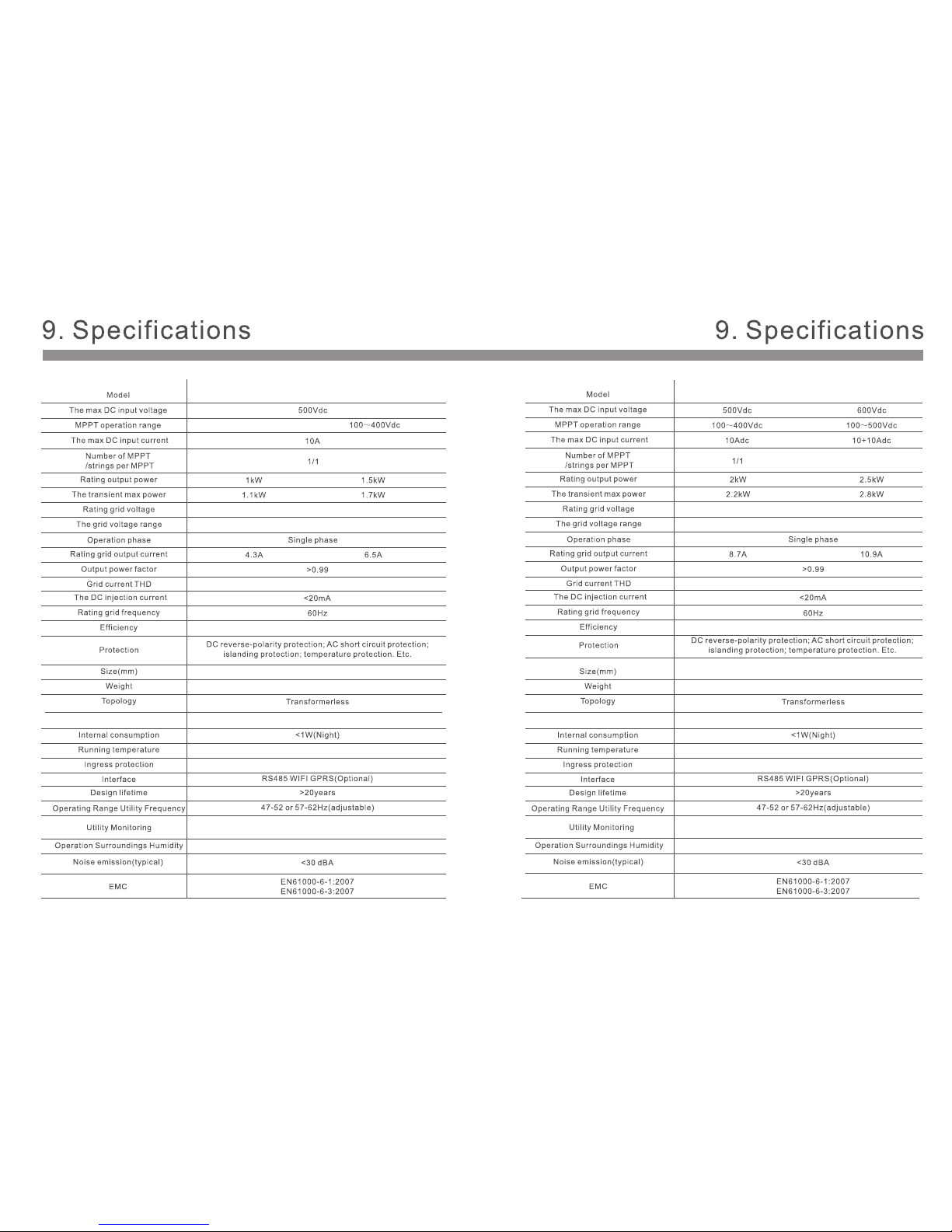
DC Sw itch Opt ional
208 V/240 V
183 ~228( for20 8V rate d)/211 ~264( for24 0V rate d)
Sol is-2K -2G-U S Sol is-2. 5K-2G -US
.27 .
DC Sw itch Opt ional
208 V/240 V
183 ~228( for20 8V rate d)/211 ~264( for24 0V rate d)
Sol is-1K -2G-U S
Sol is-1. 5K-2G -US
.26 .
NEM A 4X
70~ 400 Vdc
THD <3%
>96 .8%
-13 °F~1 40°F
339W*657H*164D mm(13.3W*25.9H*6.5D inch)
9.8kg/21.6lb
CAN/CSAC22.2 N107.1, UL1741, UL1998, UL1699B, FCC part 15, Class B
CAN/CSAC22.2 N107.1, UL1741, UL1998, UL1699B, FCC part 15, Class B
THD <3%
>96 .8% >97 .5%
339W*657H*164D mm
(13.3W*25.9H*6.5D inch)
339W*657H*172.5D mm
(13.3W*25.9H*6.8D inch)
9.8kg/21.6lb
15kg/33.1lb
NEM A 4X
-13 °F~1 40°F
2/2
0-1 00%
0-1 00%
Page 16

DC Sw itch Opt ional
208 V/240 V
183 ~228( for20 8V rate d)/211 ~264( for24 0V rate d)
Sol is-3K -2G-U S
.28 .
DC Sw itch Opt ional
208 V/240 V
183 ~228( for20 8V rate d)/211 ~264( for24 0V rate d)
Sol is-3. 6K-2G -US
.29 .
2/2
2/2
THD <3%
THD <3%
>97 .5%>97 .5%
339W*657H*172.5D mm(13.3W*25.9H*6.8D inch)
15kg/33.1lb15kg/33.1lb
339W*657H*172.5D mm(13.3W*25.9H*6.8D inch)
NEM A 4X
-13 °F~1 40°F
NEM A 4X
-13 °F~1 40°F
CAN/CSAC22.2 N107.1, UL1741, UL1998, UL1699B, FCC part 15, Class B
CAN/CSAC22.2 N107.1, UL1741, UL1998, UL1699B, FCC part 15, Class B
0-1 00%
0-1 00%
Page 17

DC Sw itch Opt ional
208 V/240 V
183 ~228( for20 8V rate d)/211 ~264( for24 0V rate d)
Sol is-4. 6K-2G -US
.31 .
DC Sw itch Opt ional
208 V/240 V
183 ~228( for20 8V rate d)/211 ~264( for24 0V rate d)
Sol is-4K -2G-U S
.30 .
THD <3%
THD <3%
>97 .8%>9 7.8%
339W*657H*172.5D mm(13.3W*25.9H*6.8D inch)
17kg/33.1lb17kg/33.1lb
339W*657H*172.5D mm(13.3W*25.9H*6.8D inch)
NEM A 4X
-13 °F~1 40°F
NEM A 4X
-13 °F~1 40°F
CAN/CSAC22.2 N107.1, UL1741, UL1998, UL1699B, FCC part 15, Class B
CAN/CSAC22.2 N107.1, UL1741, UL1998, UL1699B, FCC part 15, Class B
0-1 00%
0-1 00%
2/( 1 and 2)
10+ 18 Adc
2/( 1 and 2)
10+ 18 Adc
Page 18
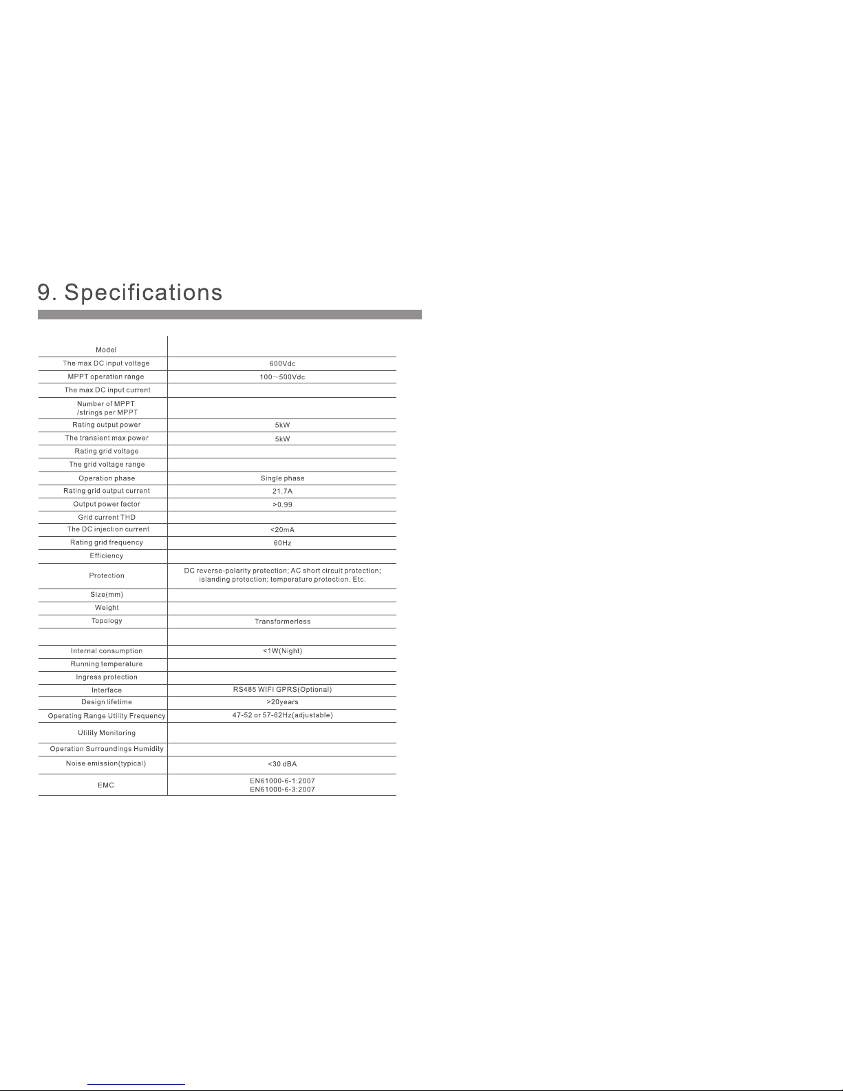
DC Sw itch Opt ional
.32.
208 V/240 V
183 ~228( for20 8V rate d)/211 ~264( for24 0V rate d)
Sol is-5K -2G-U S
2/( 1 and 2)
THD <3%
>97 .8%
17kg/33.1lb
339W*657H*172.5D mm(13.3W*25.9H*6.8D inch)
NEM A 4X
-13 °F~1 40°F
CAN/CSAC22.2 N107.1, UL1741, UL1998, UL1699B, FCC part 15, Class B
0-1 00%
10+ 18 Adc
 Loading...