

Ginlong Solis-6K, Solis-10K, Solis-15K, Solis-20K-HV, Solis-6K-LV Installation And Operation Manual
...
PV Grid Tie Inverter
Insta llati on and Opera tion Ma nual
Ver 2. 6
Solis Three Phase Inverter

1. Introduction
2. Safety Instructions
2.1 Safety Symbols
2.2 General Safety Instructions
2.3 Notice For Use
3. Overview
3.1 Front Panel Display
3.2 LED Status Indicator Lights
3.3 Keypad
3.4 LCD
4. Installation
4.1 Selecting Location for the Inverter
4.2 Mounting the Inverter
4.3 Electrical Connections
5. Start and Stop
5.1 Start the Inverter
5.2 Stop the Inverter
Contents
.1.
3
5
5
5
6
7
7
7
8
8
9
9
11
12
18
19
19
………………………
………………………………………
………………………………………………
………………………………
………………………
……………………………………………
…………………………………………………
………………………………………………
…………………
………………………………
……………………………
………………………………………
………………………………
…………………………………
……………………………………………
……………………………………
……………………………………
1.2 Packaging
4
……………………………………
1.1 Introductions
3
……………………………………
Optional
1. Introduction
Sol is thre e phase seri es PV in vert ers c ould t rans fer DC p ower fr om PV pan els int o AC
pow er and fe ed into g rid. Th ere ar e 6 models for S olis t hree p has e inve rter.
Sol is-6K , Solis-10 K, Sol is-1 5K ar e used f or 380 /400 V three p hase gr id system,
Sol is-20 K-HV is used f or 480 V thre e pha se gri d syst em.
Sol is-6K -LV, Solis-10 K-LV ar e use fo r 208/ 220 /240 V thre e phas e grid sy stem.
All 6 m odels a re transfo rmer less t opo logy g rid ti e PV inv erter.
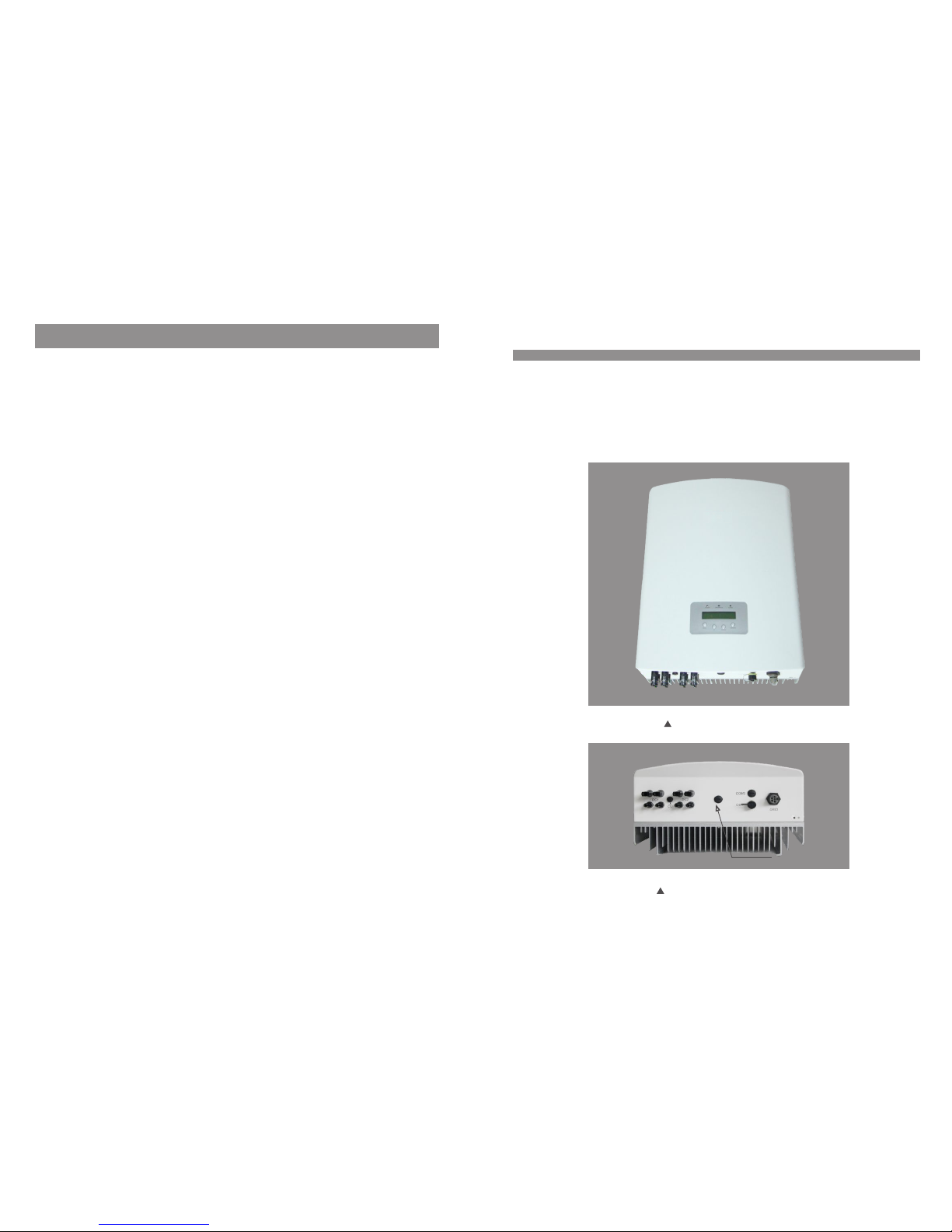
Figure 1.1 Front side view
.3.
Figure 1.2 Bottom side view
6. Operation
6.1 Main Menu
6.2 Information
6.3 Settings
6.3.1 Set Time
6.3.2 Set Address
6.4 Advanced Info.
6.4.1 Alarm Message
Contents
.2.
20
20
20
22
22
22
23
23
…………………………………………………
……………………………………………
……………………………………………
………………………………………………
……………………………………
…………………………………
………………………………………
………………………………
6.4.2 Temperature
6.4.3 Standard No.
6.4.4 Version
6.5 Advanced Settings
6.5.1 Selecting Standard
6.5.2 Grid ON/OFF
7. Maintenance
8. Trouble Shooting
9. Specifications
23
24
24
24
25
27
28
28
30
………………………………………
……………………………………
…………………………………………
…………………………………
……………………………
…………………………………
………………………………………………
…………………………………………
……………………………………………
6.4.5 Communication Data
24
…………………………
6.5.3 Calibrate Energy
27
……………………………
2.Safety Instructions
.5.
2.2 General Safety Instructions
WARNING :
Ele ctric al install atio ns mus t be do ne in ac cord ance w ith the l ocal an d natio nal
ele ctric al safe ty stan dards
CAUTIO N:
CAU TION, R ISK OF EL ECTRI C SHOCK s ymbol i ndica tes imp ortant saf ety
ins truct ions, w hich if not co rrec tly fo llo wed, c ould r esul t in elec tric sh ock.
CAUTIO N:
CAU TION, H OT SURFA CE sym bol i ndic ates s afet y instr uctio ns, whi ch if not
cor rectl y follo wed, could r esul t in bur ns.
NOTE:
NOT E symbo l indic ates im portant sa fety i nstr uct ions , whic h if not c orr ectl y
fol lowed , could r esult in som e dama ge or th e des truc tion o f the in verte r.
2.1 Safety Symbols
Saf ety sym bols us ed in thi s manual, wh ich hi ghli ght p oten tial s afet y risks a nd impo rtant
saf ety inf ormat ion, ar e liste d as follows :
WARNING :
WAR NING s ymbo l ind icat es imp orta nt safe ty inst ructi ons, wh ich if no t
cor rectl y follo wed, could r esul t in ser iou s inju ry or de ath.
Imp roper u se may re sult in pote ntia l elec tri c shoc k haza rds or b urns. T his ma nual
con tains i mportant i nstr ucti ons t hat sh ould b e foll owe d duri ng ins tall ation a nd
mai ntena nce. Pl ease read th ese in stru cti ons ca refu lly be fore us e and kee p them fo r
fut ure ref erenc e.
WARN ING:
Ple ase don ’t connect PV a rray po sitiv e(+) o r negat ive(- ) to the gr ound , it coul d
cau se seri ous da mage to t he inve rter.
.4.
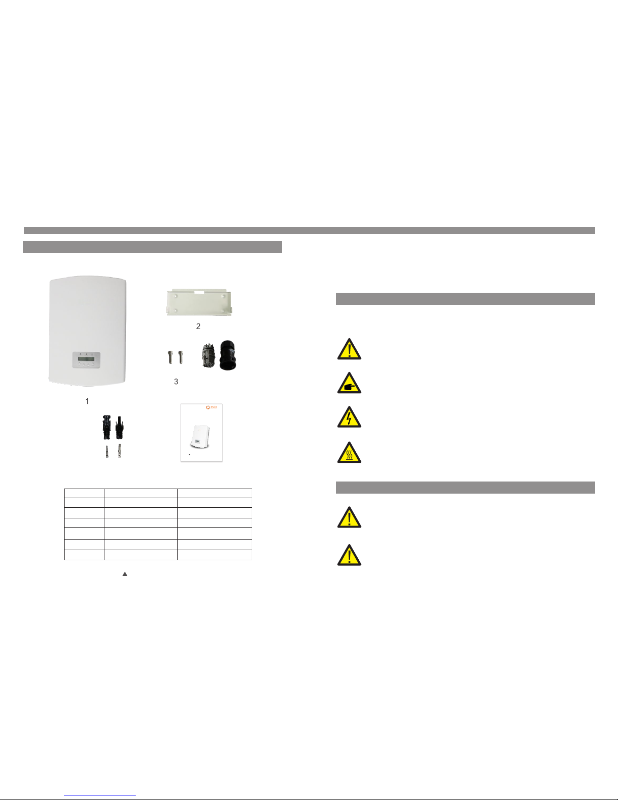
1.2 Packaging
When you receive the inverter, please check if all the parts listed below are included:
1. Introduction
Par t NO.
1
Des cript ion
PV gr id tie in verte r
2
Wal l moun ting b rac ket
3
Loc king sc rews
5
AC con necto r
6
DC co nnect ors
Man ual
7
Num ber
1
1
2
1
4 pai rs(2 fo r Solis -6K)
1
Table 1.1 Material list
4
5
6
PV Grid Tie Inve rter
Installatio n and Ope ratio n Manua l
2014, Ningbo Gin long Tech nolog ies Co. , Ltd.
C
Ver 2.5
Solis Three Phase Inverter
3. Overview
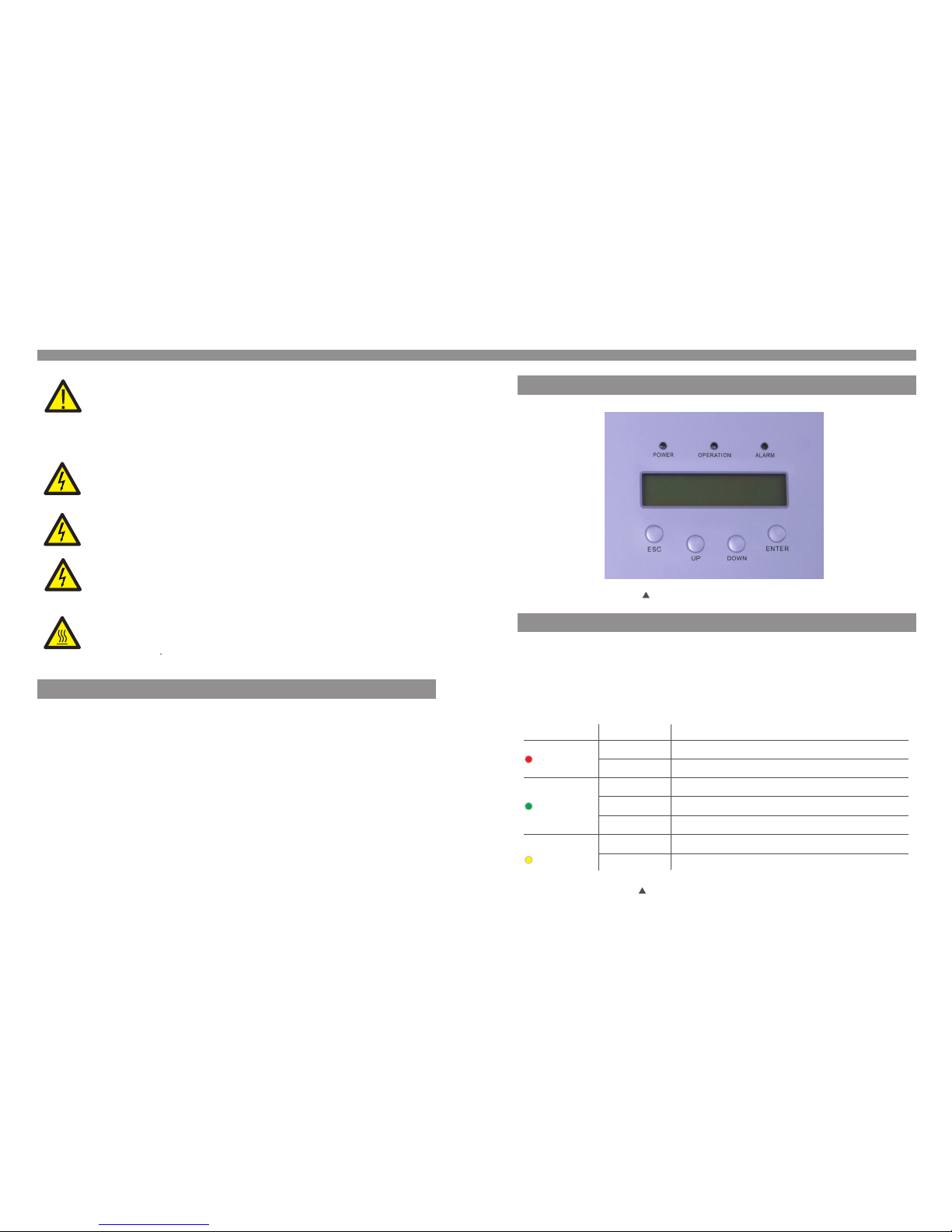
3.1 Front Panel Display
Fig ure 3.1 F ront Pa nel Dis play
3.2 LED Status Indicator Lights
The re are th ree LED s tatus i ndicator l ight s in the f ron t pane l of the i nver ter. Lef t LED:
POW ER LED (r ed) ind icates the p ower s tatu s of th e inve rter. M iddl e LED: OP ERATIO N
LED ( green ) indicate s the op erat ion s tatu s. Rig ht LED : ALA RM LE D (yel low) i ndic ates
the a larm st atus. P lease s ee Tab le 3.1 f or deta ils
Des cript ion
The i nvert er can de tect DC p ower
No DC p ower or l ow DC pow er
The i nvert er is ope ratin g prope rly.
The i nvert er has st opped t o suppl y power.
The i nvert er is ini tiali zing.
Ala rm or fau lt cond ition i s detec ted.
The i nvert er is ope ratin g prope rly.
Sta tus
ON
OFF
ON
OFF
OFF
ON
FLA SHING
Lig ht
POW ER
OPE RATION
ALA RM
Table 3 .1 Stat us Indi cator L ights
2.Safety Instructions
2.3 Notice For Use
The i nvert er has be en constru cted a ccor din g to the a ppli cabl e safet y and tec hnica l
gui delin es. Use the in vert er in in sta llat ions t hat me et the fo llowi ng sepc ifica tion ON LY:
1. Perm anent i nstal latio n is require d.
2. The in verte r must be c onnec ted to a se parat e grounded AC g roup , to whi ch no o ther
ele ctric al equi pment is con nect ed.
3. The el ectri cal ins talla tion must me et all t he app lic able r egul atio ns and st andar ds.
4. The in verte r must be i nstal led acc ording to th e inst ruct ion s stat ed in th is man ual .
5. The in verte r must be i nstal led acc ording to th e corr ect te chn ical s peci fica tions .
6. To start up the in verte r, the Gri d Suppl y Main Sw itch (AC) mu st be sw itch ed on , befo re
the s olar pa nel's DC iso lato r shal l be sw itch ed on. To st op the i nver ter, the G rid S uppl y
Mai n Switc h (AC) mu st be swi tched o ff befo re the s olar pa nel's D C isolator s hall b e
swi tched o ff.
CAUTIO N:
The P V array ( Solar p anels) sup plie s a DC vol tag e when i t is exp osed t o light .
CAUTIO N:
Ris k of elec tric sh ock fro m energy sto red in c apac ito rs of th e Inve rter. D o not
rem ove cov er until 5 min utes a fter d isc onne ctin g all so urces o f suppl y. Se rvic e
tec hnici an only. Warra nty ma y be voi ded i f any un auth oriz ed remo val of co ver.
CAUTIO N:
The s urfac e tempe ratur e of the inver ter ca n reac h up to 7 5℃ (167 F ).
To avoi d risk of burn s, do no t touc h the s urfa ce whe n inve rter is o perat ing.
Inv erter m ust be in stall ed out th e reach of chi ldre n.
WARNING :
To redu ce the ri sk of fire, br anch -cir cui t over -cur rent p rotec tive de vices
(OC PD) are r equir ed for ci rcuits con nect ed to th e Inv erte r.
The r ecomm end rated tr ip cur rent f or AC br eake r shou ld be 25 A for S olis- 6K
inv erter, 3 2A for Sol is-10K, So lis- 15K, S oli s-20 K-HV i nver ter.
CAUTIO N:
Ris k of elec tric sh ock. Do n ot remove co ver. Th ere is n o user s erv icea ble
par ts insi de. Ref er serv icing to qua lifi ed and a ccr edit ed ser vice t echni cian.
.7..6.
4. Installation
4.1 Select a Location for the Inverter
3.3 Keypad
3.4 LCD
The re are fo ur keys i n the fro nt pane l of the In verter(f rom le ft to ri ght ):
ESC , UP, DO WN and E NTE R keys . The ke ypad i s used f or:
Scr ollin g through th e disp laye d opt ions ( the UP a nd DOW N keys );
Acc ess to mo dify th e adjustab le set ting s (th e ESC an d ENTE R keys ).
3. Overview
The t wo-li ne Liqu id Crystal D ispl ay (LC D) is l ocat ed at th e fron t panel o f the Inv erter,
whi ch show s the fol lowing inf orma tion :
Inv erter o perat ion sta tus and data ;
Ser vice me ssages for o pera tor;
Ala rm mess ages and fau lt ind icat ion s.
.8.
.9.
To sele ct a loca tion fo r the invert er, the f ollo win g crit eria s houl d be cons idere d:
To avoi d over heati ng amb ient a ir te mper atur e MUST b e cons idere d when ch oosin g
the i nvert er inst allation l ocat ion. G inl ong re comm end us ing a sun s hade mi nimizing
dir ect sun light when t he amb ient a ir te mper atur e arou nd the un it exce eds 40°C.
Do no t insta ll in sma ll closed sp aces w here a ir cann ot circ ulate f reely. To av oid
ove rheat ing, al ways make su re the f low of a ir ar ound t he inv erte r is not bl ocked .
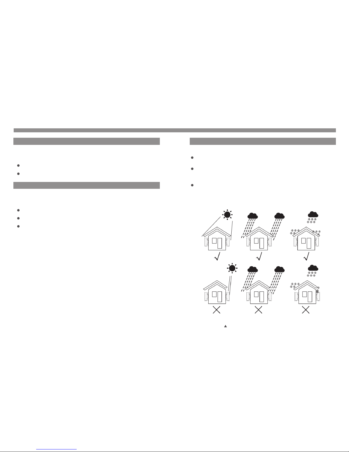
Exp osure t o direct sun ligh t will i ncr ease t he ope rati onal te mpera ture of t he inverte r and
may c ause ou tput po wer limiti ng. Gi nlon g rec omme nd inv erte r insta lled to a void direc t
sun light o r raini ng.
Fig ure 4.1 R ecomm end Instal lati on pla ce

For 1 o r more in verte r insta lled, a mini mum 12 in cle ara nce sh ould b e kept b etwee n each
inv erter o r other o bject. The bo ttom of t he inve rter sh ould be 20in c lear ance t o the
gro und.
Vis ibil ity of th e LED sta tus ind icato r lights and t he LCD l ocat ed at t he fro nt pan el of
the i nvert er shou ld be consid ered .
Adeq uate vent ilatio n must be prov ided if the in verter is t o be install ed in a confined space .
NOTE:
Not hing sh ould be stor ed on or p lace d aga inst t he inv erte r.
Ins tall on a w all or st rong st ructu re capable o f bear ing th e wei ght.
Ins tall ve rtica lly with a max imum i ncli ne of + /- 5°.If t he mounted i nver ter is t ilt ed to an
ang le grea ter tha n the maximu m note d, hea t dis sipa tion c an be in hibit ed, and m ay resu lt
in le ss than e xpected ou tput p ower.
500m m
500m m
500m m
500m m 500m m
500m m
500m m
Fig ure 4.1 I nvert er Moun ting cl earance
4. Installation4. Installation
Inv erter s hould b e mounted in a v erti cal po sit ion as s hown i n Figu re 4.3. T he ste ps to
mou nt the in verte r on the wall ar e give n as fol low s:
1. Loca te the wa ll stud s in the de sired loca tion a nd ali gn th e wall m ount b rack et over
the s tuds. M ark the m ounti ng holes. Fo r maso nry wa lls , the mo unti ng hol es shou ld be
for a s uitab le dyna bolt ty pe mountin g syst em.
2. MAKE SU RE BRA CKET IS h orizontal . Ensu re that t he A, B, C, an d D mount ing ho les
(in F igure 4 .3) ar e align ed wit h the wal l's mo st secu re poi nts (e. g. wal l studs i n case of
cla d build ing ma teri als).
4.2 Mounting the Inverter
Ple ase use s uitable fi xing s for wa ll ty pe (e. g. use d ynab olts fo r brick , mason ry, etc) .
Fig ure 4.3 I nvert er Moun ting
WARNING :
Bra cket mu st be mou nted verti call y on a ver tic al wal l surf ace.
Bra cket
M4×14 s tainl ess ste el screw
Inv erter
Sui table f ixing s crews
.10 . .11.
Fig ure 4.2 I nvert er Moun ting cl earance

4. Installation4. Installation
A
B
C
D
Inv erter
E F
4.3 Electrical Connec tions
The I nvert er is des igned for el ectr ical c onn ecti on wit hout r emovi ng the co ver. The m eani ng
of th e symbo ls located a t the bo ttom o f the i nver ter ar e list ed in Tabl e 4.1 .All e lect rica l
ins talla tions m ust be in a ccordanc e with a ll loc al an d nati onal e lect rical c odes .
Table 4.1 Terminals
+
-
Pos itive D C input t erminal
Neg ative D C input term inal
DC 1
Pos itive o r negative D C 1 inpu t term ina l
DC 2
Pos itive o r negative D C 2 inpu t term ina l
DC SW ITCH
Swi tch of DC i nput te rminals( opti onal )
COM
Com munic ation conn ecti on equ ipm ent te rmin al (Op tiona l)
GRI D
Gri d wires c onnec tion equip ment t ermi nal
3. Car efully hang the inverter o n the upper p art of the wa ll mount br acket by f itting the
hook s into the sl ot of the bra cket. Us e M4×14 stai nless st eel scre ws at holes E an d F
(in Fig ure 4.) to secure the mounti ng hooks to t he rear of th e invert er.
Fig ure 4.4 W all Mo unt Br ack et
The e lectr ical co nnection o f the in vert er mu st fol low th e step s liste d below :
1. Swit ch the Gr id Supp ly Main S witch ( AC) O FF.
2. Swit ch the D C Swi tch O FF.
3. Assem ble PV inpu t conn ect or of th e Inve rter.
Bef ore con nect ion, pl ease ma ke sur e the pol arity o f the out put vol tage of PV arr ay
mat ches th e“DC+”a nd “DC -”symbols.
Max imum 10 00Voc fo r
Sol is-6K S olis-10K So lis-1 5K Soli s-20 K-H V
Max imum 60 0Voc for
Sol is-6K -LV Sol is-1 0K-LV
Bef ore con nect ing inv erter, pleas e make su re the P V array open ci rcuit v oltag e is
wit hin the l imit of t he inve rter
Ple ase don ’t connect P V arra y posit ive or ne gativ e pole to the gro und, it c ould
cau se seri ous damages t o the inv erter
Fig ure 4.5 DC+ C onne ctor Fig ure 4.6 DC- C onne ctor
Ple ase use q ualified D C cabl e for P V sys tem.
.12 . .13 .

4. Installation4. Installation
iii ) Cri mp the co ntact p in to the w ire using a pr oper w ire cr imp er as sh own in F igur e 4.9
Fig ure 4.9 C rimp th e conta ct pin to t he wire
iv) Ins ert the c ontac t pin to th e top par t of the co nnect or and screw u p the ca p nut to
the t op part o f the con necto r (as sho wn in Fig ure 4.10).
The s teps to a ssemb le the DC c onnector s are li sted a s fol lows :
I) Stri p off the D C wire f or ab out 7m m, Dis asse mble th e conne ctor ca p nut (se e Figure 4.7 ).
ii) Ins ert the w ire int o the con necto r cap nut a nd contact p in as sh own in F igu re 4.8 .
Fig ure 4.7 D isass emble the Co nnec tor Ca p nut
Fig ure 4.8 I nsert t he Wire i nto the C onnector C ap nut a nd con tac t pin
Fig ure 4.1 0 Conne ctor with Ca p nut Sc rewe d on
Fig ure 4.11 C onne ct the DC C onnec tors to t he Inve rter
v) Th en con nect th e DC conn ector s to the in verte r. Small clic k will c onfi rm co nnec tion
(as s hown in F igure 4 .11).
4. Ass emble t he grid side c onne ctor o f the I nver ter.
For a ll AC conn ections, 2 .5- 6m m 105 ℃ c abl e is req uire d to be us ed. Ple ase mak e sure
2
the r esist ance of c able is lowe r than 1 .5 ohm . If th e wire i s long er tha n 20m, it 's
rec ommen ded to use 6mm cab le.
2
WARNING :
The re are sy mbo ls mar ked in side t he conn ector ( see
Fig ure4. 12), th e Line wire of g rid mu st be co nne cted t o ter minal ; the “L” “ 1” “2”
Ear th wire o f grid mu st be connec ted to“ ”; it is r ecom mended th at the
Neu tral wi re of gri d is connect ed to“N”te rmin al (n ot req uire d)
“L” “ 1” “2” “N ” “ ”
.14 . .15 .

4. Installation4. Installation
Fig ure 4.1 2 AC Gr id Ter mina l Conne ctor
Fig ure 4.1 3 AC Gr id Ter mina l Conne ctor In side
The s teps to a ssemb le the AC grid te rmin al con nec tors a re lis ted as f ollow s:
Fig ure 4.1 4 Conne ct Wires to th e Grid Ter mina l
Eac h Solis t hree ph ase invert er is su ppli ed wi th an AC gr id ter mina l conne ctor, which i s
in Fi gure 4. 12.
L
N
1
2
G
a) Stri p the end o f AC wire a bout 8 mm, In sert th e cable thro ugh th e jack et an d cap
nut o f conne ctor, th en inse rt the wi res to th e grid termi nal an d tigh ten t he scr ews
on th e conne ctor (a s shown i n Figur e 4.13). Ple ase tr y to pul l out t he wir e to mak e
sur e it is wel l conne cted.
Fig ure 4.1 5 Tig hten up t he cap on t he term inal
c) Conn ect the AC g rid ter minal conn ecto r to the i nve rter. S mall c lick w ill con firm
con necti on (as sh own in Fi gure 4.16) .
Fig ure 4.1 6 Conne ct AC Ter mina l Conne ctor to t he inverte r
b) Assem ble the c onnec tor and tigh ten up c ap on th e ter mina l (as sh own in F igure 4 .14).
.16 . .17 .

5. In verte r monit oring C onnectio n.
The i nvert er can be m onito red by Wi-Fi o r GPRS f unct ion s. All th e comm unic ation
fun ction s are opt ional (Fig ure 4. 17), p lea se ref er to co mmun icati on conn ectio n
ins truct ions.
Fig ure 4.1 7 Wi-Fi c ommun ication fu ncti on
Intern et
GPR S monit oring
Wi- Fi moni torin g
Sma rt phon e monitori ng
PC mo nitor ing
Web s erve r
Rou ter
Wi- Fi moni torin g
Wi- Fi box
4. Installation
.19 .
.18 .
5.1 Start the Inverter
To start up the Inverter, it is important that the following steps are strictly followed:
1. Swit ch the Su pply Ma in Swit ch (AC) O N first .
2. Swit ch the DC I solat or ON. If t he volt age of PV a rrays a re high er than star t up vol tage ,
the i nvert er will t urn on. The red L ED powe r will light , and th e LCD sh ows t he com pany 's
nam e and the i nvert er mode l.
Sol is-15 K
Fig ure 5.1 C ompan y Name and Inv erte r Mode l on LC D
3. When b oth the D C and the AC g rid sid es supply to t he inv erte r, it wi ll be re ady to
gen erate p ower. In itial ly, the in vert er will c heck both it s inte rnal p ara mete rs and t he
par amete rs of the AC g rid, to ensu re tha t they a re wi thin t he acc epta ble lim its. At th e
sam e time, t he gree n LED wil l flash and th e LCD di spla ys th e info rmat ion of
INI TIALI ZING.
4. Af ter 30- 180 se cond s (depe ndin g on loca l requ irem ent), t he inv erter w ill st art to
gen erat e power. Th e gree n LED wil l be on co ntinu ally a nd the LC D disp lays
GEN ERATIN G.
WARNING :
Do no t touch t he surf ace when the i nver ter is o per atin g. It ma y be
hot a nd caus e burns.
5.2 Stop the Inverter
To stop t he Inve rter, th e follo wing steps m ust be s tric tly follo wed:
1. Swit ch the Gr id Supp ly Main S witch ( AC) OFF.
2. Wait 30 s econ ds. Swi tch of f the DC sw itch o r pull out the DC i nput c able . All t he LED s of
the i nver ter will be off i n a minut e.
Gin long
5. Start & Stop

6. Operation
6.1 Main Menu
Dur ing no rmal o pera tion , the di spla y show s the po wer an d the operati on stat us alt erna tely
wit h each s cree n last ing fo r 10 sec onds ( see Fi gure 6 .1). Screens can al so be sc roll ed
man uall y by pre ssin g the UP a nd DOWN k eys. P ress ing th e ENTE R key gi ves ac cess t o
Mai n Menu .
Fig ure 6.1 O perat ion Ove rview
5 sec
Model name
Sta rt
Pow er 9424 W
01- 01-20 10 09:0 4
Sta tus: Ge nerat ing
01- 01-20 10 09:0 4
Inf ormat ion
Set tings
Adv anced I nfo.
Adv anced s ettin gs
UP/ DOWN
UP/ DOWN
UP/ DOWN
UP/ DOWN or
aut o-scr oll
(10 s ec)
Pre ssing t he
ENT ER key
giv es acce ss to
the m ain men u.
Pre ssing t he
ESC k ey
cal ls back t he
pre vious m enu.
Mai n Menu
The re are fo ur subm enus in the Ma in Men u (see F igu re 6.1 ):
1. Info rmati on
2. Sett ings
3. Advan ced Inf o.
4. Advan ced Set tings
6.2 Information
The S olis th ree pha se PV invert er mai n menu p rov ides a cces s to ope ratio nal dat a and
inf ormat ion. Th e info rmati on is dis played by se lect ing "I nfo rmat ion" f rom th e men u and
the n by scro lling u p or down.
6. Operation
Pre ssing t he ESC ke y retur ns to the M ain Menu. Pr essi ng the E NTE R key to l ock (F igur e
6.2 (a)) or u nlock (Fig ure 6. 2 (b)) t he sc reen .
V_D C1 350. 8V
I_D C1 5.1A
V_D C2 350. 8V
I_D C2 5.1A
V_G rid 400 .4V
I_G rid 8.1 A
Sta tus: ge nerat ing
Pow er: 148 8W
Gri d Frequ ency
F_G rid 50. 06Hz
Total E nergy
025 8458 kw h
Thi s Month : 0123k wh
Las t Month : 0123k wh
Today : 02kwh
Yeste rday: 0 1kwh
10 se c
10 se c
10 se c
10 se c
10 se c
10 se c
10 se c
10 se c
V_D C1: Sho ws input 01 vo ltag e valu e.
I_D C1: Sho ws inpu t 01 current v alue .
V_D C2: Sho ws input 02 vo ltag e valu e.
I_D C2: Sho ws inpu t 02 current v alue .
V_G rid: Sh ows gri d voltage va lue.
I_G rid: Sh ows gri d current va lue.
Sta tus: Sh ows sta tus of th e inver ter.
Pow er: Sho ws outp ut power val ue.
F_G rid: Sh ows fre quenc y of grid valu e.
Total e nergy o utput valu e (sin ce the l ast t ime
ene rgy was c leared).
Thi s Month : Tota l ener gy gene rated t his mon th.
Las t Month : Tota l ener gy gene rated l ast mon th.
Today : Tota l ener gy gene rated d uring this D ay.
Yest erda y: Total e nerg y gen erat ed las t Day.
Dis play
Dur ation
Des cript ion
Table 6 .1 Info rmati on Indi cator
5.2 Stop the Inverter
Fig ure 6.2 L ock and U nlock the Sc reen o f LCD
(b)(a)
.20 . .21 .

6. Operation
6.3 Settings
The f ollow ing sub menus are di spla yed wh en the Se tting s menu is s elect ed:
1. Set Tim e
2. Set Add ress
6.3.1 Setting Time
Thi s funct ion all ows tim e and date set ting . When t his f unct ion is s elec ted , the LC D will
dis play a sc reen as show n in Fig ure 6. 3.
NEX T=<EN T> OK=< ESC>
01- 01-20 10 16:3 7
Fig ure 6.3 S et Time
Pre ss the UP /DOWN k eys to se t time an d data. Pres s the EN TER ke y to mo ve fro m one
dig it to the n ext (fr om left t o right ). Pres s the ESC k ey to save the s etti ngs an d ret urn to
the p revio us menu .
6.3.2 Setting Address
YES =<ENT > NO=<E SC>
Set Ad dress : 02
Fig ure 6.4 S et Addre ss
Pre ss the UP /DOWN k eys to se t the add ress. Pres s the EN TER ke y to sa ve the s etti ngs.
Pre ss the ES C key to ca ncel th e change and r etur n to the p rev ious m enu.
Thi s funct ion is us ed to set t he address o f an inv erte r con nect ed to PC f or com mun icat ion
pur pose. T he add ress nu mber ca n be assigne d from “0 1”to “99”(s ee Fi gure 6 .4).
The d efaul t addre ss number of S olis t hree p has e inve rter i s “01”.
6. Operation
.23 ..22 .
6.4 Advanced Info - Tech nicia ns Only
Sel ect “Ad vanced Inf o.” fr om the M ain Menu to d ispl ay a scr een a nd be ab le to ac cess t o
the f ollow ing inf ormat ion.
1. Alar m Messa ge
2. Temper ature
3. Stan dard No .
4. Versi on
5. Comm unica tion Da ta
The s creen c an be scroll ed man uall y by pr essi ng the U P/DO WN keys . Press ing the E NTER
key g ives ac cess to a subm enu. P ress t he ES C key to r etur n to the M ain M enu.
6.4.1 Alarm Message
The d ispla y shows t he 10 latest a larm m essa ges ( see Fi gure 6 .5). S cre ens ca n be scr olle d
man ually by pres sing the UP/ DOWN keys . P ress the ESC key to r etur n t o th e pr evio us
men u.
Ala rm0: OV- G-V
Tim e: 27- 11 Data : 7171
Fig ure 6.5 Al arm Mes sage
6.4.2 Temperature
The s creen s hows th e temperat ure in side t he in vert er (se e Figu re 6.6) .
Fig ure 6.6 Tem pera ture in side th e Inver ter
Tempe ratur e
046 .6
℃
NOTE:
To access to t his ar ea is f or ful ly qu alif ied a nd acc redited t echn ici ans on ly.

6. Operation
6.4.3 Standard No.
The s creen s hows th e referenc e stan dard o f the I nver ter (s ee Fig ure 6.7 ).
Sta ndard : VDE01 26
Fig ure 6.7 E xampl e of Stan dard of the In vert er
6.4.4 Version
The s creen s hows th e model vers ion an d the so ftw are ve rsio n of the I nvert er
(se e Figur e 6.8).
Mod el: 08
Sof tware Ve rsion : D20001
Fig ure 6.8 M odel Ver sion and Sof twar e Versi on
6.4.5 Communication Data
The s creen s hows th e internal d ata of t he Inv ert er (se e Figu re 6.1 3), w hich i s for se rvic e
tec hnici ans only.
01- 05: 01 25 E 4 9D AA
06- 10: C2 B5 E 4 9D 55
Fig ure 6.9 C ommun ication Da ta
6.5 Advanced Settings - Tec hnici ans Onl y
Sel ect Adva nced Setti ngs fr om the M ain M enu to a cces s the fo llowi ng opti ons:
1. Sele ct Stan dard
2. Grid O N/OFF
3.C alibr ate Ene rgy
NOTE:
To access to t his ar ea is f or ful ly qu alif ied a nd acc redited t echn ici ans on ly.
For tech nic ians only.
6. Operation
.25 ..24 .
Thi s funct ion is us ed to sel ect the grid 's ref eren ce st anda rd (se e Figu re 6.10 ).
YES =<ENT > NO=<E SC>
Sta ndard : G59/3
Fig ure 6.1 0
NOTE:
This fun ctio n is fo r tech nic ians u se on ly.
NOTE:
Before t o usin g thi s func tio n, ple ase s et "GR ID OFF " to st op inv ert er (re fer
to Secti on 6.5 .2) .
NOTE:
The inve rter i s cus tomi zed a ccor din g to the l ocal stan dard b efo re shi ppi ng
to the cus tome r. The " User- Def" f unc tion c an be o nly us ed by the ser vice
engine er and m ust t o be all owe d by the l oca l ener gy suppli er.
6.5.1 Selecting Standard
Fig ure 6.11
OV-G -V1: 44 0V
OV-G -V1-T: 1S
Sel ectin g the Use r-Def sub me nu wil l acce ss to t he fol lowi ng sub menu (s ee Figu re 6.11) :
Bel ow is the s ettin g range for Us er-D ef. Us e thi s func tion c an cha nge the l imits m anual ly.
Pre ss the UP /DOWN k eys to se lect th e standard ( AS47 77, AS4 777 _NQ, AU S-Q- 0.9,
AUS -Q-0. 8, VDE4 105, VD E0126, UL- 240V, UL -208V, M EX-C FE, G8 3/2 , G59/ 3,
EN5 0438 DK , EN50438 IE , EN50 438 NL , EN5 0438 L, EN5 0438 T an d “Use r-D ef”
fun ction ).
Pre ss the EN TER key t o confi rm the se tting . Press the ES C key to c ance l cha nges a nd
ret urns to p revio us menu.
The s tanda rd AUS-Q-0. 9 and AUS -Q-0 .8 me an fix ed the i nver ter out put pow er fact or
to 0. 9 and 0.8 . Th ey are f or Aus tral ia Ene rgex a nd Ergo n stand ard, pleas e make s ure th e
set ting is s uitab le for lo cal requir emen t. Oth erw ise it c ould r educ e the pow er gene rated .
The d efaul t setti ng for Au stra lia is s tand ard AS4 777.
IMPORTA NT NOT E for insta llation i n Aust rali a:

6.5.2 Grid ON/OFF
Thi s funct ion is us ed to sta rt or sto p the gen erati on of Solis th ree ph ase in ver ter
(se e Figur e 6.12) .
Gri d ON
Gri d OFF
Fig ure 6.1 2 Set Gri d ON/OF F
Scr eens ca n be scrolle d manu ally b y pre ssin g the UP /DOW N keys. P ress th e ENTER k ey
to ex ecute t he sett ing. Pr ess the E SC key to r eturn to the p revi ous me nu.
6.5.3 Calibrate Energy
Mai ntena nce or re placemen t coul d clea r or ca use a di ffer ent va lue of t ota l ener gy. Use t his
fun ction c ould al low user to re vise t he val ue of t otal e nerg y to the s ame val ue as bef ore. If
the m onito ring we bsite is use d the da ta wil l be sy nchr onou s with t his set ting au tomat icall y.
(se e Figur e 6.13) .
Fig ure 6.1 3 Calib rate energ y
Pre ss the DO WN key to m ove the c ursor, Pres s the UP k ey to re vise t he value. P ress t he
ENT ER key to e xecut e the set ting. P ress th e ESC key to ret urn to t he pre vio us men u.
YES =<ENT > NO=<E SC>
Ene rgy:0 000000kW h
6. Operation6. Operation
.27 .
NOTE:
There ar e two st age f or vol tag e and fr equency l imits in Us er-D ef, p leas e
make sur e limi t 1 is in t he sco pe of l imit 2 , oth erwi se the set wi ll be fa ile d.
The init ial va lue s of the U ser -Def s tan dard a re some ref eren ce va lues . They
are not in dica tin g the va lue s of the s tan dard y ou are curr entl y usi ng.
Pres s the UP/DOW N keys to scro ll throug h items. Pre ss the ENTER key to ed it the highl ighted
item . Press the UP /DOWN key s again to chan ge the setting. Press the ENTER key to save th e
sett ing. Pres s the ESC key to can cel the change and retu rn to the previ ous menu.
NOTE:
It must se t Grid O N (re fer to S ect ion 6. 5.2) befo re the n ew st anda rd ca n
be used.
For S olis- 6K-LV/ Soli s-1 0K-LV
OV-G -V1: 22 0---2 88V
OV-G -V1-T: 0. 1---9 S
OV-G -V2: 22 0---2 88V
OV-G -V2-T: 0. 1---1 S
UN- G-V1: 1 60--- 210V
UN- G-V1- T: 0.1 ---9S
UN- G-V2: 1 60--- 210V
UN- G-V2- T: 0.1 ---1S
OV-G -F1: 50 .2-53 Hz(60 .2-63 Hz)
OV-G -F1-T: 0. 1-9S
OV-G -F2: 51 -53Hz (61-6 3Hz)
OV-G -F2-T: 0. 1-9S
UN- G-F1: 4 7-49. 5Hz(5 7-59.5Hz )
UN- G-F1- T: 0.1 -9S
UN- G-F2: 4 7-49H z(57-59H z)
UN- G-F2- T: 0.1 -9S
Bel ow is the v oltag e and freque ncy pr otec tio n limi ts ran ge for S olis th ree pha se PV
inv erter :
For S oli s-6K /Sol is-1 0K/ Soli s-15 K/So lis -20K -HV
OV-G -V1: 41 0---5 30V OV-G -F1 : 50.2 -53H z(60 .2-63 Hz)
OV-G -V1-T: 0. 1---9 S OV-G-F 1-T: 0. 1--- 9S
OV-G -V2: 43 0---5 80V OV-G -F2 : 51-5 3Hz( 61-6 3Hz)
OV-G -V2-T: 0. 1---1 S OV-G-F 2-T: 0. 1--- 9S
UN- G-V1: 3 00--- 360V UN -G-F1 : 47-49 .5Hz( 57-59 .5Hz)
UN- G-V1- T: 0.1 ---9S U N-G -F1- T: 0. 1--- 9S
UN- G-V2: 2 30--- 330V UN -G-F2 : 47-49 Hz(57 -59Hz )
UN- G-V2- T: 0.1 ---1S U N-G -F2- T: 0. 1--- 9S
.26 .

Sol is thre e phase inve rter d oes no t req uire a ny reg ular m ainte nance . Howev er, clean the
hea t-sin k will help in vert er dis sip atin g heat a nd inc rease t he life t ime of in verte r.
The d irt on th e inver ter can b e cleaned wi th a sof t brus h.
CAU TION:
Do no t touch t he surf ace when the i nver ter is o per atin g. Som e part s may be ho t
and c ause bu rns. Turn OFF y our in vert er (r efer t o Sect ion 5. 2) an d let it c ool
dow n befor e you do any mai nten ance o r cle anin g of inv erte r.
The L CD and th e LED sta tus ind icator lig hts ca n be cle ane d with c loth i f they a re too
dir ty to be re ad.
NOT E:
Nev er use any solven ts, abr asives or corr osive materi als to cl ean the invert er.
8. Trouble Shooting
The i nver ter is de sign ed in acc orda nce wi th the mo st imp ortan t inte rnat ional g rid- tied
sta ndar ds and sa fety a nd elec trom agne tic com pati bili ty requirem ents . Before deli veri ng to
the c usto mer, the i nver ter has b een su bject ed to se vera l tests t o ensu re its op tima l opera tion
and r elia bility.
In ca se of fai lure, t he LCD scree n will d ispl ay an a larm m essa ge. In t his cas e, the in verte r
may s top fee ding in to the gr id. The f ailu re desc ripti ons and thei r corr espo ndi ng ala rm
mes sages a re listed in Tabl e 8.1:
.29 ..28 .
7. Maintenance
8. Trouble Shooting
Ala rm Mess age
OV-G -V
UN- G-V
OV-G -F
UN- G-F
G-I MP
NO- GRID
OV-D C
OV-B US
UN- BUS
GRI D-INT F.
INI -FAULT
OV-T EM
GRO UND-FA ULT
Fai lure de scrip tion
Ove r grid vo ltage
Und er grid v oltag e
Ove r grid fr equen cy
Und er grid f reque ncy
Hig h grid im pedan ce
No gr id volt age
Ove r DC volt age
Ove r DC bus vo ltage
Und er DC bus v oltag e
Gri d inter feren ce
Ini tiali zatio n syste m fault
Ove r Temp eratu re
Gro und fau lt
Table 8 .1 Faul t messa ge and descr ipti on
NOTE:
If the inv erte r dis play s any a larm m ess age as l isted in Tabl e 8.1; p lease
turn off the inv erter (re fer to S ect ion 5. 2 to st op you r inverte r) and wait f or 5
minute s befo re re star tin g it (re fer to Sect ion 5.1 to st art yo ur in vert er) . If the
failur e pers ist s, ple ase c onta ct yo ur loc al distri buto r or th e serv ice c ente r.
Please k eep re ady w ith yo u the f ollo win g info rmation b efor e con tact ing u s.
1. Seri al numb er of th e Inver ter;
2. The dis trib utor /deal er of th e Inver ter (i f avai lable );
3. Inst allat ion da te.
4. The des crip tion of probl em (i. e. the al arm me ssage displ ayed o n the LCD a nd the st atus
of th e LED sta tus in dica tor lig hts. O ther re adin gs obt ained f rom th e Infor mati on sub menu
(re fer to Se ctio n 6.2) w ill als o be hel pful. );
5. PV a rray ’s conf igur ation ( e.g. n umber of pane ls, ca pacit y of pan els, nu mber o f stri ngs, et c.);
6. Your c ontac t deta ils.
ILe ak-FAU LT
Rel ay-FAU LT
DCi nj-FAU LT
Hig h Grid le akage c urren t
Rel ay chec k fault
Hig h DC inje ction c urren t

9. Specifications
Ope ratin g Range U tilit y Frequ ency
Mod el
The m ax DC inp ut volt age
MPP T opera tion ra nge
The m ax dc inp ut curr ent
Num ber of MP PT/st rings p er MPPT
Rat ed outp ut powe r
The m ax. tra nsien t power
Rat ed grid v oltag e
The g rid vol tage ra nge
Ope ratio n phase
Rat ed grid o utput c urren t
Out put pow er fact or
Gri d curre nt THD
The d c injec tion cu rrent
Rat ed grid f reque ncy
Max . Effic iency
Pro tecti on
Siz e(mm)
Wei ght
Topol ogy
Int ernal c onsum ption
Run ning te mpera ture
Ing ress pr otect ion
Int erfac e
Des ign lif etime
Uti lity Mo nitor ing
Ope ratio n Surro undin gs Humi dity
EMC
100 0Vdc
15+ 15Adc
2/1
400 Vac
313~4 70Vac( adjus table )
Thr ee phas e
>0. 99
<4% (Total TH D)
<20 mA
50/ 60Hz
>97 .5%
430 W*600H* 220Dm m
27k g
Tran sform erle ss
-2 5~60℃
IP6 5
Rs4 85 WIFI G PRS(O ption al)
>20 years
47- 52 or 57- 62Hz( adjus table )
0~95%
EN6 1000- 6-1:2 007
EN6 1000- 6-3:2 007
Sol is-6K
200~8 00Vdc
6kW
6.6 kW
8.7 Aac
<6W (Nigh t)
Isl andin g prote ction V F ina ccord ance wi th UL 174 1,
AC AC
G59 /3, AS47 77,VD E 0126- 1-1, VD E 4105, C EI 0-21 ,CQC
.31 ..30 .
9. Specifications
Ope ratin g Range U tilit y Frequ ency
Mod el
The m ax DC inp ut volt age
MPP T opera tion ra nge
The m ax dc inp ut curr ent
Num ber of MP PT/st rings p er MPPT
Rat ed outp ut powe r
The m ax. tra nsien t power
Rat ed grid v oltag e
The g rid vol tage ra nge
Ope ratio n phase
Rat ed grid o utput c urren t
Out put pow er fact or
Gri d curre nt THD
The d c injec tion cu rrent
Rat ed grid f reque ncy
Max . Effic iency
Pro tecti on
Siz e(mm)
Wei ght
Topol ogy
Int ernal c onsum ption
Run ning te mpera ture
Ing ress pr otect ion
Int erfac e
Des ign lif etime
Uti lity Mo nitor ing
Ope ratio n Surro undin gs Humi dity
EMC
Sol is-10 K
100 0Vdc
200~8 00Vdc
18+ 18Adc
2/2
400 Vac
313~4 70Vac( adjus table )
Thr ee phas e
>0. 99
<4% (Total TH D)
<20 mA
50/ 60Hz
>97 .5%
430 W*600H* 220Dm m
Tran sform erle ss
-2 5~60℃
IP6 5
RS4 85 WIFI G PRS(O ption al)
>20 years
47- 52 or 57- 62Hz( adjus table )
0~95%
EN6 1000- 6-1:2 007
EN6 1000- 6-3:2 007
<6W (Nigh t)
Isl andin g prote ction V F in acc ordan ce with U L 17 41,
AC AC
G59 /3, AS47 77,VD E 0126- 1-1, VD E 4105, C EI 0-21 ,CQC
Sol is-15 K
15k W
15k W
21. 7Aac
30k g
18+ 18Adc
2/2
10k W
11kW
14. 5Aac
Sol is-20 K-HV
20k W
20k W
24A ac
480 Vac
427~5 23Vac( adjus table )

.32 .
Sol is-6K -LV
15+ 15Adc
150~5 00Vdc
600 Vdc
6kW
6.6 kW
208 /220/ 240Vac
180~2 70Vac( adjus table )
16. 6/15. 7/14. 4Aac
>97 .2%
27k G
Ope ratin g Range U tilit y Frequ ency
Mod el
The m ax DC in put vol tage
MP PT ope ratio n range
The m ax dc inp ut curr ent
Rat ed outp ut powe r
The t ransi ent max p ower
Rat ed grid v oltag e
The g rid vol tage ra nge
Ope ratio n phase
Rat ing gri d outpu t curre nt
Out put pow er fact or
Gri d curre nt THD
The d c injec tion cu rrent
Rat ed grid f reque ncy
Max . Effic iency
Pro tecti on
Siz e(mm)
Wei ght
Topol ogy
Int ernal c onsum ption
Run ning te mpera ture
Ing ress pr otect ion
Int erfac e
Des ign lif etime
Uti lity Mo nitor ing
Ope ratio n Surro undin gs Humi dity
EM C
Num ber of M PPT /stri ngs per MPP T
2/2
Tran sform erle ss
-2 5~60℃
IP 65
RS 485 WI FI G PRS (Opti onal)
>20 years
47- 52 or 57- 62Hz( adjus table )
0~95%
EN 61000 -6-1: 2007
EN 61000 -6-3: 2007
<6W (Nigh t)
430 W*600H* 220Dm m
>0. 99
<4% (Total T HD)
<20 mA
50/ 60Hz
Thr ee phas e
Isl andin g prote ction V F i nac corda nce wit h UL 174 1,
AC A C
G59 /3, AS4 777, VDE 0 126-1 -1, VD E 4105 , CEI 0 -21,C QC
9. Specifications
Sol is-10 K-LV
18+ 18Adc
10k W
10k W
25/ 25/24 Aac
 Loading...