

Gina 6000N-5, 6000NV-5, 8000N-5, 8000NV-5 User Manual
USER'S MANUAL
Models : 6000N-5/6000NV-5/8000N-5/8000NV-5

GINA 6000N-5,6000NV-5,8000N-5, & 8000NV-5 User’s Manual
TABLE OF CONTENTS
GENERAL INFORMATION 1-1
Introduction 1-1
GINA Models 1-1
GINA 6000N-5 / 8000NV-5 1-1
GINA 8000N-5 / 8000NV-5 1-1
System Requirements 1-2
Spread Spectrum Technology 1-2
Advantages of Spread Spectrum Technology 1-2
Definitions of Terms 1-3
FCC Requirements 1-5
FCC Statement 1-6
Customer Support 1-6
Product Returns 1-6
Safety Considerations 1-7
GINA MODELS 6000N-5, 6000NV-5, 8000N-5, & 8000NV-5 2-1
Overview 2-1
Operation 2-1
GINA Programming Overview 2-1
General Operation 2-3
Front Panel 2-3
Rear Panel 2-3
Setup Mode 2-4
Repeater Setup 2-4
Getting Started 2-6
Point-to-Mulitpoint Without Repeater 2-6
Point-to-Multipoint With Repeater 2-7
Channel Frequency Table 2-9
Voice Operation (Models 6000NV-5 and 8000NV-5 Only) 2-12
Command Set 3-1
Specifications 3-7
6000N-5/6000NV-5 3-7
8000N-5/8000NV-5 3-9
Limited Warranty 4-1
General 4-1
Warranty Limitations 4-1
APPENDIX A: RS-232 Configuration Data A-1
APPENDIX B: Using an External Antenna with GINA B-1
APPENDIX C: System Block Diagram C-1
APPENDIX D: The ASCII Character Set D-1
i-1
©2001 GRE America, Inc. All rights reserved. This material is the property of GRE America, Inc. Copying or reproducing this material
is strictly prohibited. All violators shall be prosecuted to the fullest extent of the law.
3/01 (rev. 3)

GINA User’s Manual
ACCESSORY NOTES
Instructions for EIA 442 / RS-232 Full Duplex Converter (12-4002)
Instructions for EIA485 / RS-232 Half Duplex Converter (12-4003)
ANTENNA NOTES
2.4 GHz Patch Antenna (30-0033)
900 MHz Omni Directional Magnetic Mount Mobile Antenna (30-0034)
900 MHz Omni Directional Antenna (30-0035)
900 MHz Yagi Antenna (30-0036)
2.4 GHz Linear Antenna (30-0037)
2.4 GHz Omni Directional Antenna (30-0038)
2.4 GHz Parabolic Dish Antenna (30-0050)
APPLICATION NOTES
World-Wide Applications
Application Note 7100: Connection of GINA 6000N-5/8000N-5 to a Model 170 Traffic Controller
Application Note 7104: Configuration of GINA RJ22 Jack
Application Note 7111: Basic GINA Testing Procedures
Application Note 7113: How Far Will It Go?
Application Note 7117: Connection of GINA to Allen Bradley Series 5 PLC
Application Note 7118: GINA Software Repeater Polling Active Path Reassignment
PRODUCT NOTE
Technical Information Note 7106
QUICK SETUP NOTE
Windows® HyperTerminal quick setup guide
i-2
©2001 GRE America, Inc. All rights reserved. This material is the property of GRE America, Inc. Copying or reproducing this mate rial
is strictly prohibited. All violators shall be prosecuted to the fullest extent of the law.
3/01 (rev. 3)

Introduction
GINA 6000N-5 / 6000NV-5
General Information
GINA User’s Manual
General Information
This document is the User’s Manual for the GINA transceiver Models :
6000N-5,6000NV-5,8000N-5 and 8000NV-5.
NOTE: Read this manual completely before you try to use any GINA
product.
Model 6000N-5 is a standard GINA transceiver. Model 6000NV-5 has an
additional voice handset for audio communication. GINA 6000N-5 is a
stand-alone, high frequency data transceiver using spread spectrum technology. GINA 6000N-5 has a standard RS-232 serial data interface that
can be driven asynchronously at rates to 38.4 K baud. GINA 6000N-5
receives and transmits data in the frequency range of 902 to 928 MHz at
air speeds to 128 Kbps. GINA 6000N-5 can perform point-to-point or
point-to-multipoint communication. GINA 6000N-5 contains a packet
controller module with a custom communication protocol. GINA 6000N5 implements a subset of standard packet framing with a built-in Cyclic
Redundancy Check (CRC). As the GINA 6000N-5 performs a CRC, if
data is corrupted, GINA 6000N-5 will discard that data. To assure accurate data transmission your system (peripheral) is responsible for error
verification.
GINA 8000N-5 / 8000NV-5
Model 8000N-5 is a standard GINA transceiver. Model 8000NV-5 has an
additional voice handset for audio communication. GINA 8000N-5 is a
stand-alone, high frequency data transceiver using spread spectrum technology. GINA 8000N-5 has a standard RS-232 serial data interface that
can be driven asynchronously at rates to 38.4 Kbps. GINA 8000N-5
receives and transmits data in the frequency range of 2.404 - 2.478 GHz at
air speeds to 128 Kbps. GINA 8000N-5 can perform point-to-point or
point-to-multipoint communication. GINA 8000N-5 contains a packet
controller module with a custom communication protocol that provides
communications handshaking, error detection, packet sequencing, flow
control, and supports three repeaters to extend the communication range.
GINA 8000N-5 implements a subset of standard packet framing with a
built in Cyclic Redundancy Check (CRC). As the GINA 8000N-5 performs a CRC, if data is corrupted GINA will discard that data. To assure
accurate data transmission your system (peripheral) is responsible for
error verification.
1-1
© 2000 GRE America, Inc. All rights reserved. This material is the property of GRE America, Inc. Copying or reproducing this material
is strictly prohibited. All violators shall be prosecuted to the fullest extent of the law.
3/01 (rev. 3)
General Information
GINA User’s Manual
System Requirements
For all GINA models, the only system requirement is an EIA232
(RS-232) peripheral or a personal computer (PC). When using a PC, any
communications software package such as BitCom©, Procomm©,
Crosstalk
©
, or Windows 95/98
©
Hyper Terminal mode.
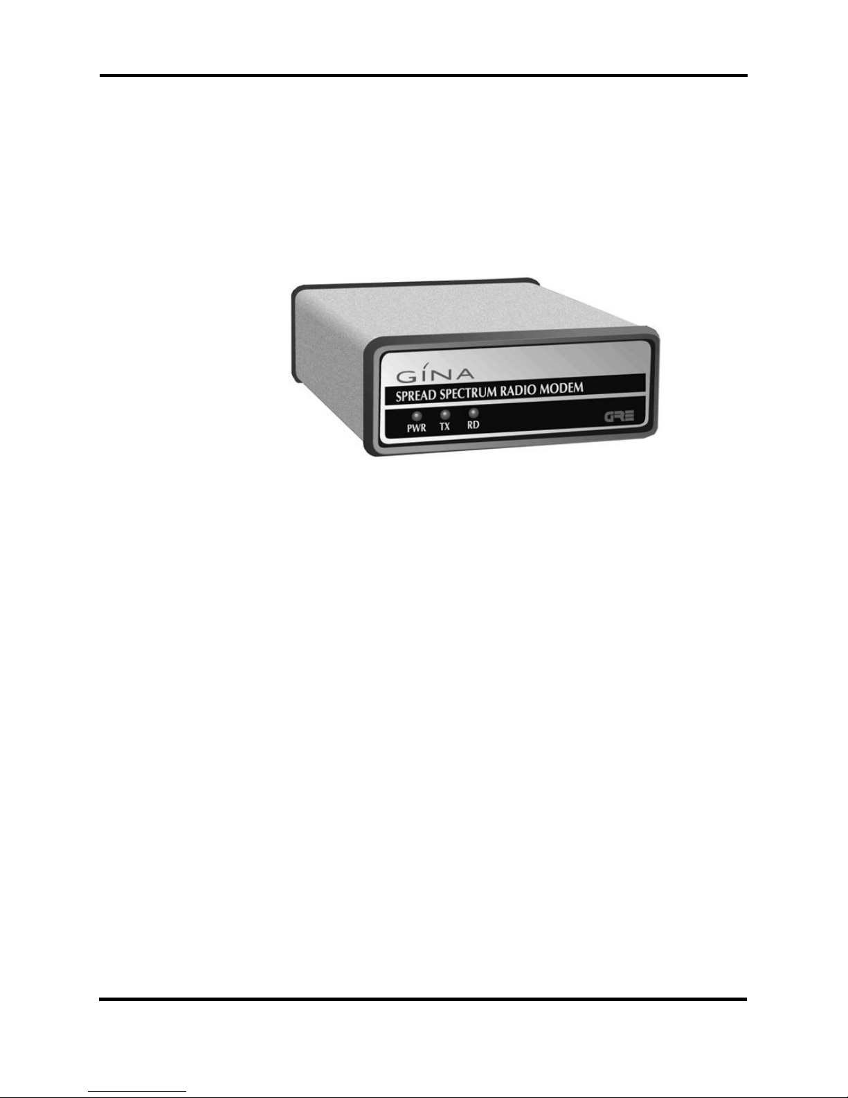
GINA is a highly secure spread spectrum radio.
Figure 1-1. The GINA Transceiver
Spread Spectrum Technology
GINA uses spread spectrum technology, a technique originally developed
by the U.S. military during World War II, to prevent the jamming of communications signals. Spread spectrum technology uses a narrow bandwidth radio frequency and spreads it over a wider portion of the
bandwidth. Since the signal is spread out over the band, it renders narrow
band jammers virtually ineffective. Additionally, the spread spectrum
band can be used with low probability of interception, which is an ideal
method of communication since it is ‘radio silent’ to a conventional
receiver.
Advantages of Spread Spectrum Technology
Spread spectrum technology has many advantages. Among them are:
• System flexibility. Additions can be made easily.
• Interference immunity. Spread spectrum radios are immune
to noise.
1-2
© 2001 GRE America, Inc. All rights reserved. This material is the property of GRE America, Inc. Copying or reproducing this mat erial
is strictly prohibited. All violators shall be prosecuted to the fullest extent of the law.
3/01 (rev. 3)
General Information
GINA User’s Manual
• Error-free communication. Automatic error detection is
built into some models.
• Cost. Spread spectrum technology is inexpensive compared
to an equivalent hard-wired installation.
• Data throughput. Spread spectrum technology is a transpar-
ent, real-time, point-to-point, and point-to-multipoint wireless network.
• Multi-channel . Spread spectrum radios have multiple chan-
nels that can be dynamically changed with software. It allows
for repeaters, redundant base stations, and overlapping
antenna cells. A great advantage is in the dynamic control of
radio signal ‘peaks’ and ‘valleys.’
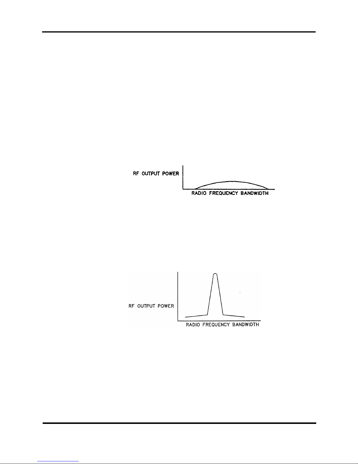
A typical spread spectrum radio signal is shown in Figure 1-2.
Definitions of Terms
Figure 1-2. Spread Spectrum Radio Signal
A typical narrow band signal is shown in Figure 1-3.
Figure 1-3. Narrow Band Radio Signal
DATA INTERFACE — The asynchronous interface port provided for
connectivity is a EIA-232 (RS232) standard.
© 2000 GRE America, Inc. All rights reserved. This material is the property of GRE America, Inc. Copying or reproducing this material
is strictly prohibited. All violators shall be prosecuted to the fullest extent of the law.
DIRECT SEQUENCE — Direct sequence is a technique that takes a
1-3
3/01 (rev. 3)

General Information
GINA User’s Manual
narrow-band signal and spreads it over a broader portion of the radio
frequency band.
KEY-UP TIME — The time that a radio requires when switching from
transmit to receive and vice-versa. There is no key-up time required due
to an internal buffer. Except for Models 5000N38 and 7000N38, data can
be received and transmitted through the RS-232 port simultaneously in a
full duplex mode using TDD (time division duplex).
NOTE: Key-up time and spreading code length are interrelated. In a
direct sequenced technique, the spread sequence system must (in real
time) attempt to match its despreading code with the incoming radio
signal in order to determine the validity of the data. The longer the
spreading code, the longer the receiver must search before it can determine that a valid data signal is being transmitted.
SYNCHRONIZATION — Applied each time that the radio switches
between transmit and receive, synchronization produces direct overhead
on each transmitted message, thereby reducing radio efficiency. In applications involving very long, constant messages (such as a large file transfer), synchronization time becomes less of a deciding factor.
MULTIPATH — Radio signals may take several paths to reach the
intended receiver. The receiver must sort out the main path from all the
‘ghost’ images. The longer the spreading factor and/or the faster the raw
data rate, the more difficult (and eventually impossible) it is to sort out the
signals, resulting in a loss of robust communication.
NUMBER OF CHANNELS — The number of channels varies per
GINA model. Models 6000N5, and 6000NV-5 have 21 channels provided
in the 902 - 928 MHz frequency range. Models 8000N-5 and 8000NV-5
have 37 channels provided in the 2.404 - 2.478 GHz frequency range.
Note that the channels are overlapping and, depending on the unit separation, only one channel may be used.
PROCESSING GAIN MEASUREMENTS — Since processing gain is
a function of the RF bandwidth of the transmitted signal compared to the
bit rate of the data, the theoretical calculation is:
10Log(Spreading Code Rate) x (Main Lobe Factor)
RF Data Rate
NOTE: Assuming that the RF main lobe of [sin x/]2 for direct sequence is
0.88 (main lobe factor) times the bandwidth spreading code clock rate.
RANGE — The communication distance between GINA’s may vary
according to environment and application. (Robustness and range are
almost interchangeable terms; robustness and range vary according to the
antenna system used.)
1-4
© 2001 GRE America, Inc. All rights reserved. This material is the property of GRE America, Inc. Copying or reproducing this mat erial
is strictly prohibited. All violators shall be prosecuted to the fullest extent of the law.
3/01 (rev. 3)

General Information
GINA User’s Manual
RAW DATA RATE — Response time of data transmission/reception.
The raw data rate is factory set to 128 Kbps.
ROBUSTNESS — GRE America, Inc. believes that an RF link should be
‘as good as wire.’ Robustness is closely related to range. Variables for
robustness and range include:
• Transmitter Output Power
• Receiver Sensitivity
• Spreading Code Length
• Raw Data Rate
• Antenna Configuration
NOTE: Spreading Code Length, Raw Data Rate, Robustness, and Multipath are interrelated; all terms are defined in this section.
SPREADING CODE LENGTH — A shorter spreading code length
results in better performance in measurable areas such as cost, actual data
throughput, size, range, and robustness.
FCC Requirements
A longer spreading code length reduces the possibility of unintended signal interruption and/or regulatory implications. GRE America has taken
all the above criteria and used a spreading code length of 127 chip with
four different codes selectable by channel.
SYSTEM RESPONSE TIME — Raw data rate, reflected by transmission response time. The minimum response time is 12 msec.
The FCC has allocated the frequencies between 902 – 928 MHz and
2.404 and 2.478 GHz for use with spread spectrum technology and does
not require the end user to obtain an FCC license to operate a GINA transceiver.
NOTE: Professional installers who replace GRE-provided whip antennas
with one not approved by GRE America, must obey FCC regulations concerning effective radiated power in the U.S. or the effective rules in the
destination country relating to ERP. For detail specifications, refer to
FCC Rules Part 15.247.
© 2000 GRE America, Inc. All rights reserved. This material is the property of GRE America, Inc. Copying or reproducing this material
is strictly prohibited. All violators shall be prosecuted to the fullest extent of the law.
1-5
3/01 (rev. 3)

General Information
GINA User’s Manual
FCC Statement
This equipment has been tested and found to comply with the limits for a
Class B digital device, pursuant to Part 15 of the FCC Rules. These limits
are designed to provide reasonable protection against harmful interference in a residential installation. This equipment generates, uses, and can
radiate radio frequency energy and, if not installed and used in accordance with the instructions, may cause harmful interference to radio communications. However, there is no guarantee that interference will not
occur in a particular installation. If this equipment does cause harmful
interference to radio or television reception (which can be determined by
turning the equipment off and on) the user is encouraged to try to correct
the
interference by one or more of the following measures:
• Re-orient or relocate the transceivers.
• Increase the separation between equipment and transceivers.
• Connect the equipment into a different outlet or circuit differ-
ent from the one where the receiver is connected.
• Consult a dealer or an experienced radio technician for help.
Customer Support
Product Returns
Shielded cables and I/O cords must be used for this equipment to comply
with relevant FCC regulations.
Changes or modifications not expressly approved in writing by GRE
America, Inc. may void the user’s authority to operate this equipment.
If you need answers to technical questions or require information about
product updates, please contact GRE America’s Technical Support Team
at:
Tel: (650) 591-1400
Fax: (650) 591-2001
(800) 233-5973 (USA)
Between 8:00 A.M. and 5:00 PM, Pacific Time
Email : support@greamerica.com
1-6
© 2001 GRE America, Inc. All rights reserved. This material is the property of GRE America, Inc. Copying or reproducing this mat erial
is strictly prohibited. All violators shall be prosecuted to the fullest extent of the law.
3/01 (rev. 3)
If, after speaking to a technical support person, it is determined that your
GINA unit requires servicing, call GRE and request a RMA number for
repair and return units. Write the RMA number on the outside of the ship-

ping box for reference.
NOTE: Units returned without an RMA number will not be accepted.
For further information, please write us at:
Safety Considerations
For your safety, here are some things that you should do and not do:
DO read this manual completely before using GINA.
General Information
GINA User’s Manual
GRE America, Inc.
425 Harbor Boulevard
Belmont, CA 94002 USA.
Attn: Customer Support
DO follow all instructions carefully.
DO use the same caution with GINA as you would use with any
electrical appliance.
DO NOT try to use GINA for purposes for which it was not intended.
DO NOT locate GINA in an area that does not have adequate ventila-
tion for cooling.
DO NOT use a ‘universal’ battery adapter with GINA. Only use the
adapter supplied with the unit.
© 2000 GRE America, Inc. All rights reserved. This material is the property of GRE America, Inc. Copying or reproducing this material
is strictly prohibited. All violators shall be prosecuted to the fullest extent of the law.
1-7
3/01 (rev. 3)

GINA 6000N-5, 6000NV-5, 8000N-5, & 8000NV-5
GINA User’s Manual
GINA Models 6000N-5, 6000NV-5, 8000N-5, & 8000NV-5
Overview
Models 6000N-5 and 8000N-5 are standard GINA transceivers. Model
6000NV-5/8000N-5 have an additional voice handset for audio communication. GINA 6000N-5/8000N-5 are stand-alone, high frequency data
transceivers using spread spectrum technology. GINA 6000N-5/8000N-5
have a standard RS-232 serial data interface that can be driven asynchronously at rates to 38.4 K baud. GINA 6000N-5 receives and transmits
data in the frequency range of 902 to 928 MHz at air speeds of up to 128
Kbps. GINA 8000N-5 receives and transmits data in the frequency range
of 2.404 - 2.478 GHz at air speeds to 128 Kbps. GINA 6000N-5/8000N-5
can perform point-to-point or point-to-multipoint communication. GINA
6000N-5/8000N-5 contains a packet controller module with a custom
communication protocol. GINA 6000N-5/8000N-5 implements a subset
of standard packet framing with a built-in Cyclic Redundancy Check
(CRC). As the GINA 6000N-5/8000N-5 performs a CRC, if data is corrupted, GINA will discard that data. To assure accurate data transmission
your system (peripheral) is responsible for error verification.
Operation
This section contains operating instructions for the GINA transceiver.
GINA Programming Overview
GINA is a transparent communication device. Depending on your peripheral software, GINA can be controlled to work as a point-to-point or
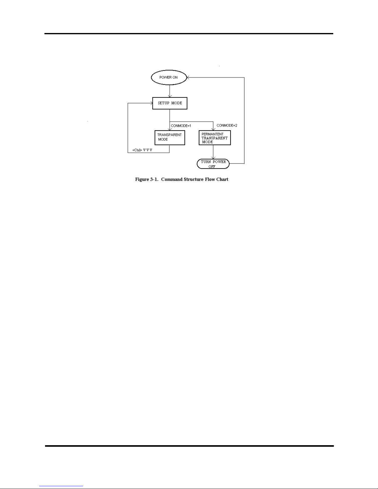
point-to-multipoint transceiver. Figure 2-1 is a flowchart illustrating the
command structure overview.
2-1
© 2001 GRE America, Inc. All rights reserved. This material is the property of GRE America, Inc. Copying or reproducing this mat erial
is strictly prohibited. All violators shall be prosecuted to the fullest extent of the law.
3/01 (rev. 3)
GINA 6000N-5, 6000NV-5, 8000N-5, & 8000NV-5
GINA User’s Manual
Figure 2-1. Command Structure Flowchart
As illustrated in figure 2-1, there are three modes of operation:
1. SETUP MODE. The setup mode is where the parameters of GINA
can be changed. There are 17 dedicated commands that may be
altered to accommodate different timing application.
NOTE: Any changed parameters are automatically stored in
memory.
2. TRANSPARENT MODE. The transparent mode converts GINA
into a mode that is completely transparent to the user. The data is
immediately transmitted if the PACWAIT or PACSIZE command
limits are exceeded.
NOTE: To return to the setup mode from the transparent mode,
press <CTRL> + <V> three times in succession.
3. PERMANENT TRANSPARENT MODE. The permanent trans-
parent mode is similar to the transparent mode except that there is
no escape character to return to the setup mode. Once in the permanent transparent mode, the only way to return to setup mode is by
turning the radio off (reset).
© 2001 GRE America, Inc. All rights reserved. This material is the property of GRE America, Inc. Copying or reproducing this material
is strictly prohibited. All violators shall be prosecuted to the fullest extent of the law.
3/01 (rev. 3)
2-2

GINA 6000N-5, 6000NV-5, 8000N-5, & 8000NV-5
GINA User’s Manual
General Operation
Front Panel Indicators
As shown in Figures 2-2 operating indicators and Voice option Jack
located on the front panel and consist of:
1. PWR LED (Light Emitting Diode). This LED is lit when power is
applied to the transceiver.
2. TX LED . Indicates that a signal is being transmitted by GINA.
3. RD LED. Indicates that a signal is being received by GINA.
4. Voice Handset Jack. Standard RJ-11 telephone jack for the GINA
handset (Model 6000NV-5 and 8000NV-5 only).
NOTE: GINA only operates with the handset supplied with the
unit. Do not attempt to use a standard telephone handset.
Rear Panel
(4) Optional Voice
Handset Jack
(3) Receiver Indicator
(2) Transmit Indicator
(1) Power Indicator
Figure 2-2. GINA Transceiver Front Panel
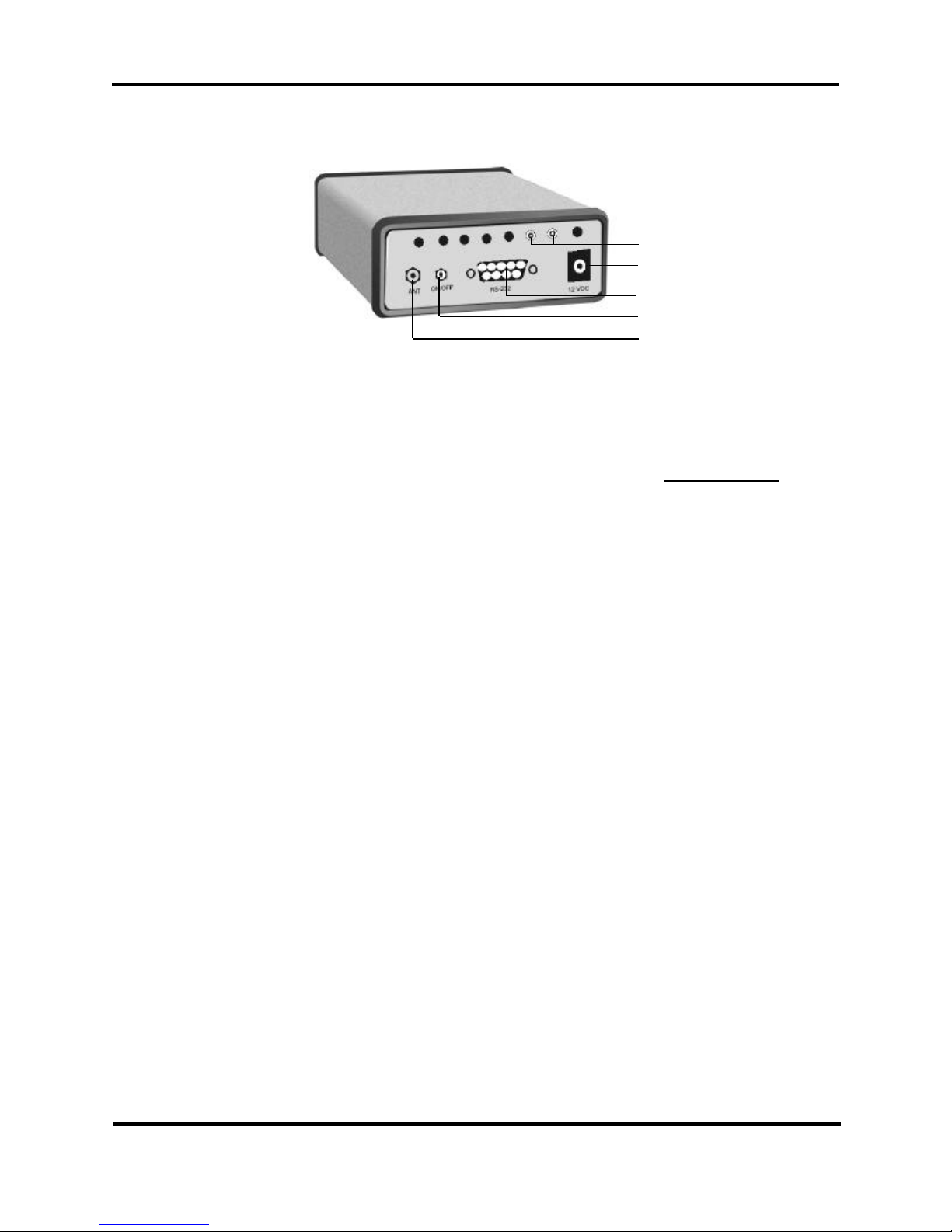
As shown in Figure 2-3, the rear panel contains a power switch and three
connectors, as follows:
1. The GINA antenna jack (non-standard SMA type).
2. ON/OFF toggle switch. Controls power to the transceiver.
3. RS-232 (DB9) connector. Data interface to PC or DTE equipment.
4. 12 VDC. Power connector
2-3
© 2001 GRE America, Inc. All rights reserved. This material is the property of GRE America, Inc. Copying or reproducing this mat erial
is strictly prohibited. All violators shall be prosecuted to the fullest extent of the law.
3/01 (rev. 3)
Setup Mode
GINA 6000N-5, 6000NV-5, 8000N-5, & 8000NV-5
GINA User’s Manual
5. RSSI for Receiver Signal Strenght
.
(5) Optional RSSI Jack
(4) 12 V DC Power Supply
Jack (center pole positive)
(3) DB9 RS-232 Connector
(2) Power ON/OFF Switch
(1) Antenna Connector
Reverse SMA Type
Figure 2-3. GINA Transceiver Rear Panel
When GINA is turned on, type the word GINA within 5-seconds to enter
the setup mode (or, if the CONMODE command is set to “1” (transparent
mode), press <CTRL> + <V> three times). Once in the setup mode, the
radio responds with the following prompt:
Repeater Setup
SET UP > Enter command sets
NOTE: Any PC with standard communication software or a dumb terminal peripheral can be used to send ASCII commands to GINA. In addition, GINA is initially factory set at 9600 baud. The communication
software must be initially set up for 9600,8,N,1.
After completion, type QUIT and GINA enters either transparent mode
or transparent permanent mode (depending on how CONMODE is set).
If there are no changes in the parameters (commands), GINA enters one
of the transparent modes 5 seconds after it has been turned on.
GINA can be set up to work as a dedicated repeater to extend its range.
Below is a description on how to put GINA into a repeater configuration:
Setting Repeater Unit
1. Set RID (Repeater ID) to the desired ID number (between 1 and
99).
© 2001 GRE America, Inc. All rights reserved. This material is the property of GRE America, Inc. Copying or reproducing this material
is strictly prohibited. All violators shall be prosecuted to the fullest extent of the law.
3/01 (rev. 3)
2. Set ENR (Enable Repeater)
2-4

GINA 6000N-5, 6000NV-5, 8000N-5, & 8000NV-5
GINA User’s Manual
0 = OFF
1 = Permanent mode (ENR remains enabled after power
down).
2 = Temporarily ON mode (ENR disables if the power is
turned off).
Setting Transmitter Unit (Host)
1. Set TXID (Transmitter ID) to the desired ID number (between 1
and 99).
2. Set TXP (Transmit Path) equal to that of the RID of the Repeater
ID.
3. Set RID (Repeater ID) to zero.
4. Set ENR (Enable Repeater) to zero.
Setting Receiver(s) Parameters (Remote)
1. Set TXID of the remote radio different from the TXID of the Transmitter (Host) radio, 1...99.
NOTE: If you do not want to receive the message from other
remote units, set all the remote TXID’s the same.
IMPORTANT: If the host and remote(s) TXID’s are set to the
same value, neither radio will display any data.
2. If the receiver(s) is going to respond back to the transmitter through
a repeater, you must set the receiver(s) as follows:
a. Set TXP (Transmit Path) equal to that of the RID of the
Repeater ID.
b. Set RID and ENR to zero.
After parameters are set, type QUIT to enter the transparent mode.
2-5
© 2001 GRE America, Inc. All rights reserved. This material is the property of GRE America, Inc. Copying or reproducing this mat erial
is strictly prohibited. All violators shall be prosecuted to the fullest extent of the law.
3/01 (rev. 3)
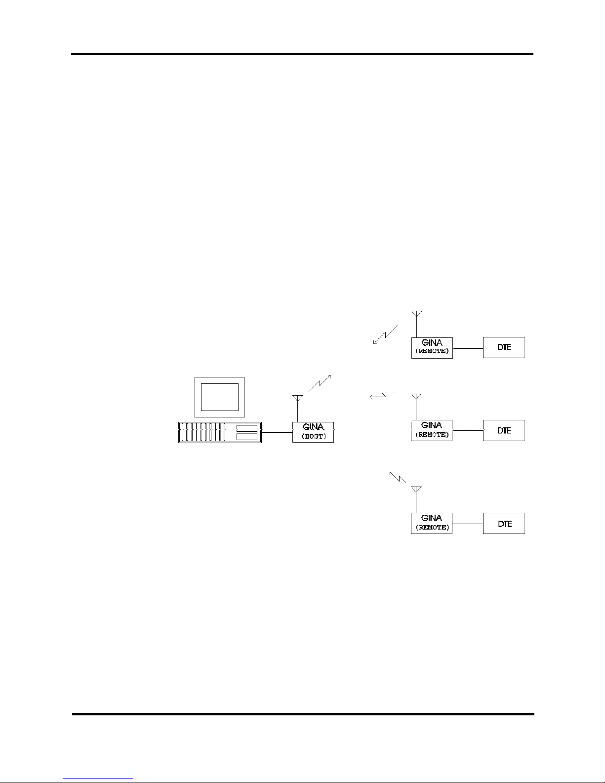
Getting Started
Figures 2-4 and 2-5 illustrate quick and easy ways to setup and manipulate a point-to-multipoint application (without a repeater and using a
repeater).
Point-to-Multipoint Without Repeater
1. GINAs arrive factory set with default parameters. Install the
GINAs, wait 5 seconds after power up, and they are ready to transfer data.
2. If parameters were changed, go into SETUP mode and enter
RESET. This resets the GINA parameters back to the factory
default settings.
GINA 6000N-5, 6000NV-5, 8000N-5, & 8000NV-5
GINA User’s Manual
© 2001 GRE America, Inc. All rights reserved. This material is the property of GRE America, Inc. Copying or reproducing this material
is strictly prohibited. All violators shall be prosecuted to the fullest extent of the law.
3/01 (rev. 3)
Figure 2-4. Point-to-Multipoint Without Repeater
3. If you do not want the remote(s) to receive any data being transmitted from other remote(s), give the same Transmit ID (TXID) value
to all remote(s). Make sure the Host TXID is different than the
Remote(s) TXID.
2-6

GINA 6000N-5, 6000NV-5, 8000N-5, & 8000NV-5
GINA User’s Manual
Point-to-Multipoint With Repeater
Set the Host, Repeater and Remote GINAs as follows (refer to figure 5-5).
Setting Host Unit
1. Set TXID = *1 (Transmit ID)
2. Set TXP = *99 (Transmit path) must equal RID value set in
Repeater
All other parameters are set to default.
Setting Remote Units
1. Set TXID = *2-98. Remote TXIDs must be different from the host
TXID.
2. Setting remote TXIDs with all of the same value will not allow
Remotes to communicate with other remotes.
3. Setting the remote TXIDs to different values will allow remotes to
intercommunicate.
Note: By using matching and different values, various communication paths
can be established. All communication path MUST GO THROUGH THE
REPEATER. Timing considerations for the repeater unit must be resolved
when programming equipment used in the application
Setting Repeater Unit
1. Set RID = *99
2. Set ENR = 1
All other parameters at default values
* Example values
2-7
© 2001 GRE America, Inc. All rights reserved. This material is the property of GRE America, Inc. Copying or reproducing this mat erial
is strictly prohibited. All violators shall be prosecuted to the fullest extent of the law.
3/01 (rev. 3)
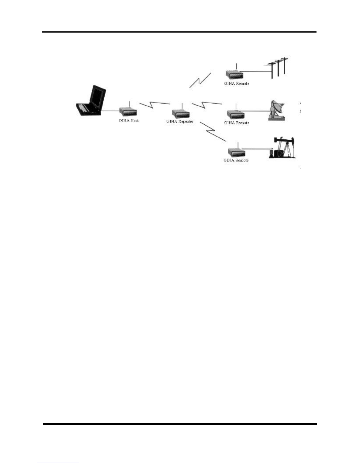
GINA 6000N-5, 6000NV-5, 8000N-5, & 8000NV-5
Figure 2-5. Point-to-Multipoint With Repeater
GINA User’s Manual
© 2001 GRE America, Inc. All rights reserved. This material is the property of GRE America, Inc. Copying or reproducing this material
is strictly prohibited. All violators shall be prosecuted to the fullest extent of the law.
3/01 (rev. 3)
2-8

GINA 6000N-5, 6000NV-5, 8000N-5, & 8000NV-5
GINA User’s Manual
Channel Frequency Table
CHANNEL CODE SWITCH SETTINGS
FOR GINA MODELS 6000N-5 AND 6000NV-5
CHANNEL FREQUENCY (MHz) PN CODE
1 905.055 1
2 906.055 2
3 907.055 3
4 908.055 4
5 909.055 2
6 910.055 3
7 911.055 4
8 912.055 1
9 913.055 3
10 914.055 4
11 915.055 1
12 916.055 2
13 917.055 4
14 918.055 1
15 919.055 2
16 920.055 3
17 921.055 1
18 922.055 2
19 923.055 3
20 924.055 4
21 925.055 2
2-9
© 2001 GRE America, Inc. All rights reserved. This material is the property of GRE America, Inc. Copying or reproducing this mat erial
is strictly prohibited. All violators shall be prosecuted to the fullest extent of the law.
3/01 (rev. 3)
 Loading...