

Gina 2000-64K User Manual
USER'S MANUAL
Model : 2000-64K
TM
Overview
GINA User’s Manual
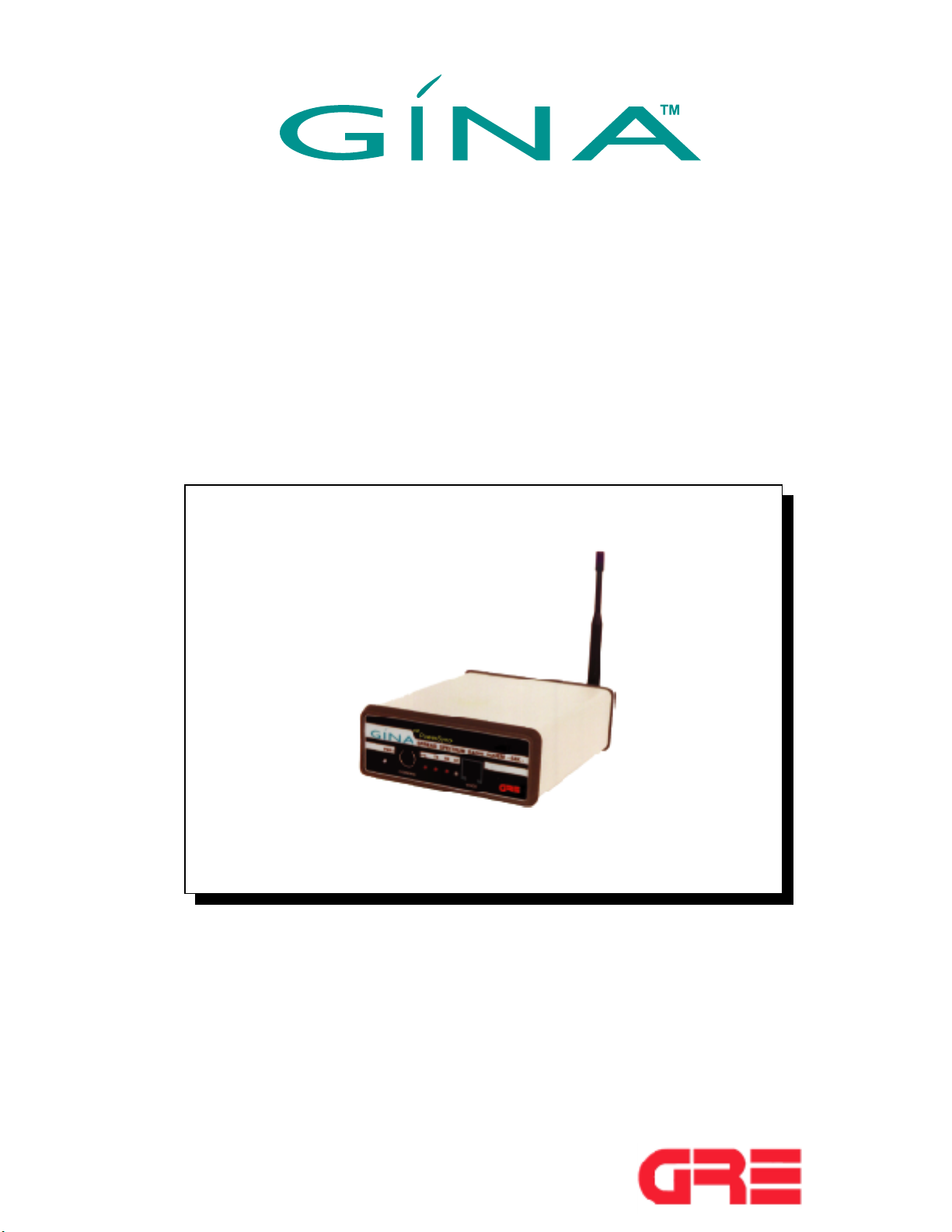
GINA MODEL 2000-64K
GINA Model 2000-64K is a stand-alone, high frequency data transceiver using
spread spectrum technology . GINA 2000-64K capabilities include
synchronous data transmission at speeds to 64 Kbps at the data port with EIA 562/
RS-232, EIA530/RS-530, and V.11 (V.35) interfaces. GINA 2000-64K receives
and transmits data in the frequency range of 2.404 - 2.478 Ghz at air speeds of
up to 186 Kbps. Communicating at this speed allows GINA 2000-64K to be a
full (TDD) duplex link. GINA can be configured to be used as a point-topoint communication device. GINA 2000-64K contains a packet controller
module with a custom communication protocol that provides communications
handshaking, cyclic redundancy checking (CRC), packet sequencing, and
flow control.
Figure 6-1. GINA 64K Transceiver
Operation
This section contain operating instructions for the GINA transceiver,
including controls and indicators, DTE requirements, channel selection, and voice
operation.
1-1
©1999 GRE America, Inc. All rights reserved. This material is the property of GRE America, Inc. Copying or reproducing this material is strictly prohibited. All violators shall be prosecuted to the fullest extent of the law.
1/99
GINA User’s Manual
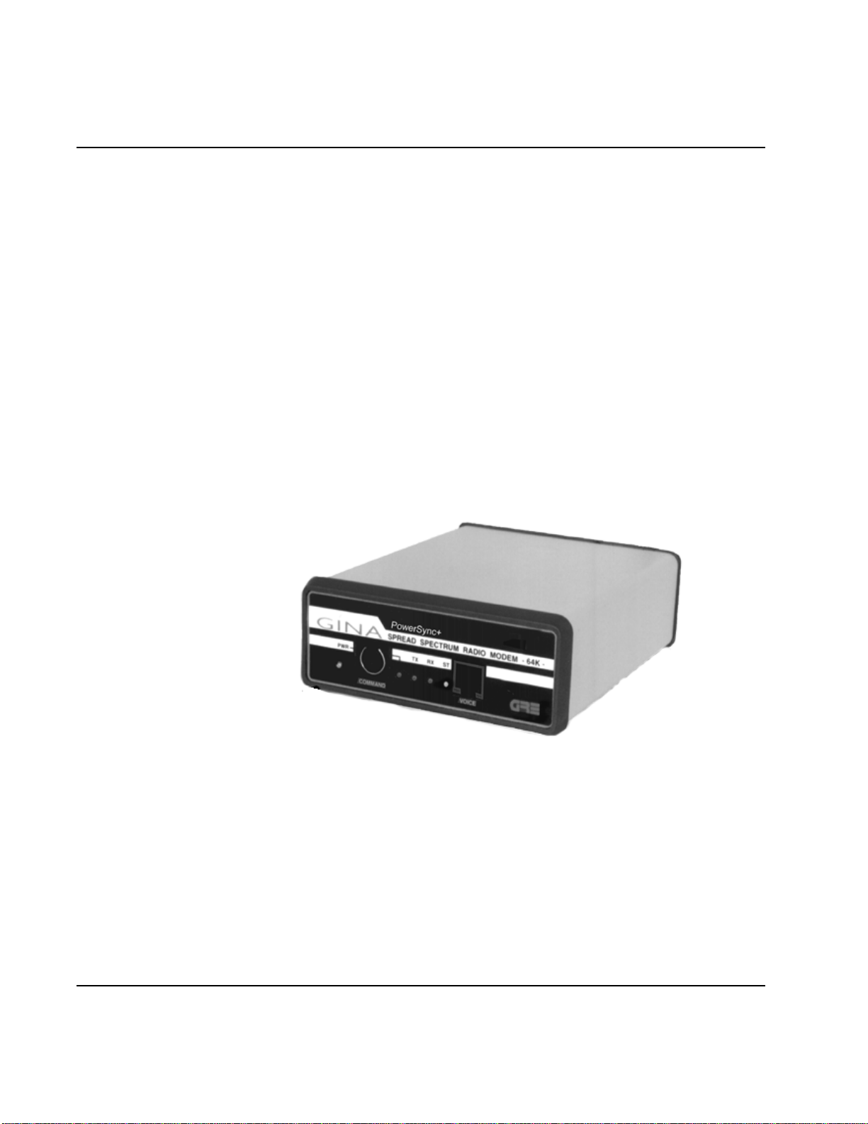
Controls and Indicators
Front Panel
As shown in Figure 6-2, operating indicators, a voice handset jack, and
the command data port are located on the front panel and consists of:
1. PWR LED (Light Emitting Diode). This LED is lit when
power is applied to the transceiver.
2. TX LED. Indicates that a signal is being transmitted by GINA.
3. RX LED. Indicates a receiving condition on GINA.
4. ST LED. When green, GINA is receiving good data. When
red, data has errors, GINA is receiving bad data, or the GINA
units are not synchronizing.
5. Voice Handset Jack. Standard RJ22 telephone jack for the
GINA handset.
6. RS-232 Command Control Data Port. Used for programming
during GINA setup. This port communicates at 9600 kbps
asynchronous only .
NOTE: GINA only operates with the handset supplied with the unit.
Do not attempt to use a standard telephone handset.
Voice Handset Jack
Status LED
Receive LED
Transmit LED
Power LED
GINA Setup Port
Power ON/OFF Switch
Figure 6-2. GINA Transceiver Front Panel
©
1999 GRE America, Inc. All rights reserved. This material is the property of GRE America, Inc. Copying or re-producing this
material is strictly prohibited. All violators shall be prosecuted to the fullest extent of the law.
1-2
1/99
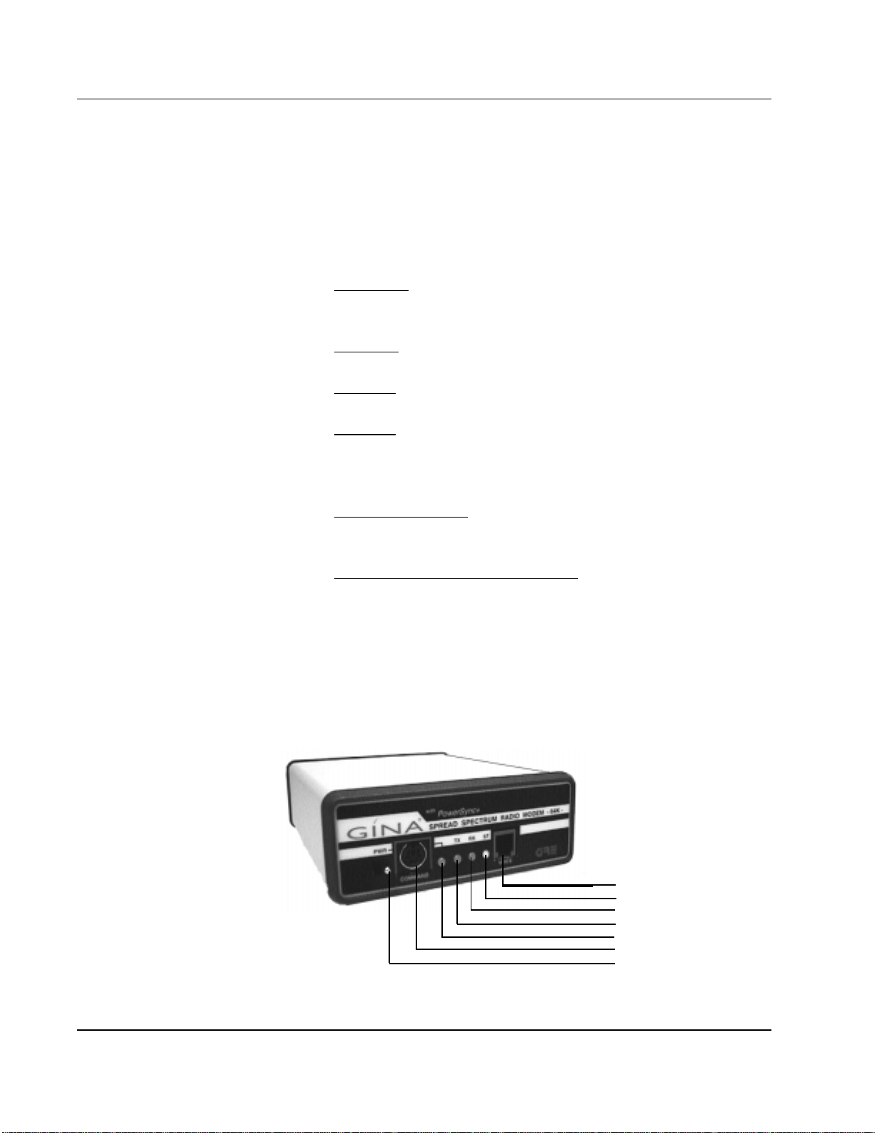
Rear Panel
GINA User’s Manual
As shown in Figure 6-3, the rear panel contains three connectors:
1. The GINA antenna jack (reverse SMA type).
2. Data Connector (DB-25).
3. 12 VDC. Power connector for the GINA AC to DC power converter.
The center connector is 12 VDC positive; the outside is grounded.
12 - Volt DC
Power Supply Jack
Center Pole Positive
Receiver Signal Strength
Indicator Jacks
DB25 RS-232, RS-530
or V.11/V.35 Connector
Antenna Connector
Reverse SMA Type
Figure 6-3. GINA Transceiver Rear Panel
GRE GINA Interface Board Commands
Cyclic Redundancy Check
CK=00 Disable cyclic redundancy check.
CK=01 Enable cyclic redundancy check.
Master / Slave
One radio must always be in control of the transmit and receiver timing.
MS=00 Slave
MS=01 Master (control unit)
©1999 GRE America, Inc. All rights reserved. This material is the property of GRE America, Inc. Copying or re-producing this
material is strictly prohibited. All violators shall be prosecuted to the fullest extent of the law.
1/99
1-3

GINA User’s Manual
Data Filter Selection
RF Channel Selection
Channel selection should be the same on both slave and master.
T ransmit Key ON
FL=01 FL=02 FL=03 FL=04
Factory Set to FL=02
CH=01~12
TX=00 This setting is for normal operation.
TX=01 10 sec transmit - test purposes only
T ransmit Clock Selection
Data Speed Selection
Revision of Software
This is factory set but may be determined by checking the Display Status.
The correct settings must be used.
CS=00 Internal transmit clock
CS=01 External transmit clock
CS=02 Loop back command (slave only). This means clock
and data lines are looped back. txd=rxd, ctxc=rxc
DR=01 9.6 Kbps Synchronous
DR=02 19.2 Kbps Synchronous
DR=03 38.4 Kbps Synchronous
DR=04 56 Kbps Synchronous
DR=05 64 Kbps Synchronous. This setting is also used to
allow asynchronous data communication
automatically at speeds of 1.2 to 19.2 Kbps.
RV=15
©1999 GRE America, Inc. All rights reserved. This material is the property of GRE America, Inc. Copying or
re-producing this material is strictly prohibited. All violators shall be prosecuted to the fullest extent of the law.
1/99
1-4

Display Status
GINA User’s Manual
Follows any carriage return. Examples:
GINA LOCAL ST A TUS =
CD=00 CK=00 CH=01 CS=00 DR=05 DV=01 HF=00
ID=01 IN=01 MS=01 PO=01 FL=02 RV=15 TX=00
ELAPSED SECONDS = 000000060
ERRORED SECONDS = 000000000
GINA REMOTE ST A TUS:
CD:00 CK:00 CH:01 CS:00 DR:05 DV:01 HF:00
ID:02 IN:01 MS:00 PO:01 FL=02 R V:15 TX:00
ELAPSED SECONDS = 000000120
ERRORED SECONDS = 000000001
Data or Voice
DV=00 Voice mode, data flow is de-activated. Voice is full-duplex
through the handset.
DV=01 Data mode, voice operation is de-activated.
Radio Transmit Hardware Flow
HF=00 Transmit and receiver are automatic.
HF=01 RTS high activates transmit and receive.
Transmit Clock Interface
IN=01 RS-232
IN=02 RS-449/V.11(.35)
This must be set in programming to operate, but specified at time of order for
hardware. Hardware is factory configured only .
1-5
©1999 GRE America, Inc. All rights reserved. This material is the property of GRE America, Inc. Copying or re-producing this
material is strictly prohibited. All violators shall be prosecuted to the fullest extent of the law. 1/99
 Loading...