

Page 1

Network Camera (HostCAMF44)
User Manual
English
Page 2

Page 3

C
- 3 -
© G.i.N. GmbH, 2018
Intelligente Datenlogger
Network Camera (HostCAMF44) Manual
Version 10-2018
Legal Notice
We reserve the right for substantive changes in this documentation without notice. Although this
documentation has been prepared to the best of our knowledge and with the greatest care, errors cannot be
totally ruled out. The user is solely responsible for any damages or losses of use that may occur as a result
of using this manual. If you notice any errors in this document, or have any suggestions on how it could be
improved, please send it to us.
All technical information, text, images and charts, including their layout, are protected by the prevailing legal
regulations for the protection of intellectual property, especially the copyright law. Every unauthorized usage
is a possible violation of these regulations.
Other product names and / or company names listed in this documentation may be trademarks of other
owners, whose rights must be similarly protected.
© Copyright 2018, G.i.N. Gesellschaft für industrielle Netzwerke GmbH
G.i.N. Gesellschaft für industrielle Netzwerke GmbH (G.i.N. GmbH)
Raiffeisenstr. 15
D-64347 Griesheim
Germany
Tel: ++49 6155 8259-0
Fax: ++49 6155 8259-11
E-Mail: Info@gin.de
Internet: http://www.gin.de
Page 4

- 4 -
© G.i.N. GmbH, 2018
Intelligente Datenlogger
Network Camera (HostCAMF44) Manual
Table of Contents
1 Features .................................................................................................................. 5
2 General ................................................................................................................... 8
3 Camera Settings ..................................................................................................... 9
3.1 Change Camera IP Address ............................................................................................ 10
3.2 Set Date and Time ........................................................................................................... 11
3.3 Image Resolution ............................................................................................................. 13
3.4 Transfer Image Data to the Data Logger ......................................................................... 15
3.5 Action Rules ..................................................................................................................... 17
3.6 Changing Capture Mode ................................................................................................. 20
4 Installing Activation License ............................................................................... 21
4.1 Data Logger Based HostCAM License ............................................................................ 21
4.2 Camera-based HostCAM License ................................................................................... 21
4.3 Information about Installed HostCAM Licenses .............................................................. 23
5 Camera IP Address in the Data Logger System ................................................. 25
5.1 Enter or Change IP Addresses via LTL ........................................................................... 25
5.2 Enter or Change IP Addresses via GLWebDisplay ......................................................... 25
6 LTL Control ........................................................................................................... 26
6.1 Permanent Recording of Camera Images ....................................................................... 30
7 Change History ..................................................................................................... 33
Page 5

C
- 5 -
© G.i.N. GmbH, 2018
Intelligente Datenlogger
Network Camera (HostCAMF44) Manual
1 Features
Control unit:
Camera Model AXIS F44
Resolutions
1920x1080 (1080p)1 to 480x270
1280x720 to 480x270
Frame rate
1080p without WDR: 12.5/15 fps (50/60 Hz)
720p without WDR: 25/30 fps (50/60 Hz)
720p with WDR: 12.5/15 fps (50/60 Hz)
Video streaming
Multiple, individually configurable streams in H.264 and Motion
JPEG
Axis Zipstream technology in H.264
Controllable frame rate and bandwidth
VBR/MBR H.264
Quad view, max 1080p resolution
25/30 fps (50/60 Hz) with 720p capture mode
12.5/15 fps (50/60 Hz) with 1080p capture mode
Image settings
Compression, colour, brightness, sharpness, contrast, white
balance, exposure value, exposure control, exposure zones, local
contrast, image rotation, Corridor Format, text and image overlay,
privacy mask, mirroring of images
Wide Dynamic Range – Forensic Capture1: Up to
120 dB depending on scene
Image buffer 120 MB
Memory 1024 MB RAM, 256 MB Flash
Power supply
Power over Ethernet (PoE) IEEE 802.3af/802.3at type 1, class 3
(max. 12.95 W)
8 to 28 V, max. 13.33 W
Connectors
RJ-45 for 10BASE-T/100BASE-TX PoE
RJ-12 for the sensor unit
6-pin terminal block for four configurable inputs/outputs
(12 V output), max load 50 mA
Mic/line in (3.5 mm), line out (3.5 mm)
5-pin terminal block RS232
2-pin terminal block for 8 to 28 V input
Operating conditions
Relative Humidity 10 to 85 % (non-condensing)
-30 … 60 °C
Weight Control unit: ca. 542 g
Approvals
ECE R10 rev.04, EN 50121-4, EN 50581, IEC/EN/UL 60950-1,
IEC 60068-2-1, IEC 60068-2-2, IEC 60068-2-14,
IEC 60068-2-30, IEC 60068-2-60, IEC 60068-2-78,
IEC 60529 IP4X, IEC 60721-3-5 5M3 (vibration, shock),
IEC 62236-4, EN 55024, EN 61000-6-1, EN 61000-6-2,
EN 61000-3-2, EN 61000-3-3
EN 55022 class A, FCC part 15 subpart B class A,
ICES-003 class A, VCCI class A,
1
: Valid for sensor units that support it
Page 6

- 6 -
© G.i.N. GmbH, 2018
Intelligente Datenlogger
Network Camera (HostCAMF44) Manual
C-tick AS/NZS CISPR 22 class A, KCC KN22 class A, KN24
Dimensions 51 x 121 x 121 mm
Sensor unit Axis F1005-E:
Camera model AXIS F1005-E, IP66/I67-rated
Image sensor 1/2.8” (effective) progressive scan RGB CMOS
Lens
Fixed iris
2.8 mm, F2.0
With F44 in 1080p: Horizontal viewing angle: 113°
Vertical viewing angle: 62°
With AXIS F44 in 720p: Horizontal viewing angle: 73°
Vertical viewing angle: 41°
Resolutions Max. 1920x1200/1080
Minimum illumination Colour: 0.3 lux
Shutter time
HDTV 720p 25/30 fps: 1/28000 s to 2 s
1080p 12.5/15 fps: 1/22500 s to 2 s
Operating conditions
-30 °C to 55 °C
Relative humidity 10 to 100 % (non-condensing)
Dimensions 69 mm ø 30 mm
Weight With 12 m cable: 366 g
Approvals
ECE R10 rev.04, EN 50121-4, IEC/EN/UL 60950-1,
IEC 60068-2-1, IEC 60068-2-2, IEC 60068-2-14,
IEC 60068-2-30, IEC 60068-2-78, IEC 60529 IP4X, IEC 62236-4,
EN 55022 Class B, EN 55024, EN 61000-3-2, EN 61000-3-3,
EN 61000-6-1, EN 61000-6-2, FCC Part 15 Subpart B Class B,
ICES-003 Class B, VCCI Class B, C-tick AS/NZS CISPR 22 Class B,
KCC KN22 Class B, KN24, EN 50581
IEC 60068-2-60, IEC 60529 IP66/IP67,
IEC 60721-3-5 5M3 (vibration, shock), IEC/EN/UL 60950-22,
NEMA 250 Type 4X
Sensor unit Axis F1035-E:
Camera model AXIS F1035-E, IP66/I67-rated
Image sensor 1/2.8” (effective) progressive scan RGB CMOS
Lens
Fixed iris
1.3 mm, F2.8
With F44 in 1080p: Horizontal viewing angle: 194°
Vertical viewing angle: 113°
With AXIS F44 in 720p: Horizontal viewing angle: 112°
Vertical viewing angle: 66°
Resolutions Max. 1920x1200/ 1080
Minimum illumination Colour: 0.3 lux
Shutter time
HDTV 720p 25/30 fps: 1/28000 s to 2 s
1080p 12.5/15 fps: 1/22500 s to 2 s
Operating conditions -30 °C to 55 °C
Page 7

C
- 7 -
© G.i.N. GmbH, 2018
Intelligente Datenlogger
Network Camera (HostCAMF44) Manual
Relative Humidity 10 to 100 % (condensing)
Dimensions 69 mm ø 30 mm
Weight W ith 12 m cable: 370 g
Approvals
ECE R10 rev.04, EN 50121-4, IEC/EN/UL 60950-1,
IEC 60068-2-1, IEC 60068-2-2, IEC 60068-2-14,
IEC 60068-2-30, IEC 60068-2-78, IEC 60529 IP4X, IEC 62236-4,
EN 55022 Class B, EN 55024, EN 61000-3-2, EN 61000-3-3,
EN 61000-6-1, EN 61000-6-2, FCC Part 15 Subpart B Class B,
ICES-003 Class B, VCCI Class B, C-tick AS/NZS CISPR 22 Class B,
KCC KN22 Class B, KN24, EN 50581
IEC 60068-2-60, IEC 60529 IP66/IP67,
IEC 60721-3-5 5M3 (vibration, shock), IEC/EN/UL 60950-22,
NEMA 250 Type 4X
Page 8

- 8 -
© G.i.N. GmbH, 2018
Intelligente Datenlogger
Network Camera (HostCAMF44) Manual
2 General
The Network Camera (HostCAMF44) is a digital camera exclusively controlled by the GL53xx via an
Ethernet interface.
Digital images or image sequences can be recorded with up to 4 sensor units. They are saved directly on the
external storage medium of the data logger, not on the data logger ring buffer.
It is possible to record images from up to 8 sensor units in specific use cases tested and verified by G.i.N.
(e.g. via 2 HostCAMF44).
The cameras can be connected via an Ethernet switch (e.g. GLX310) to the GL53xx. The IP addresses of
the 4 cameras are entered in the data logger system with LTL (see chap. 6).
» To operate the Network Camera (HostCAMF44) together with the data logger, a data logger based or
camera-based license is required (see chap. 4).
» The simultaneous operation of more than 4 sensor units is NOT recommended by G.i.N.
» When connecting more than one camera, the IP addresses must not be consecutive.
The camera can be supplied using Power over Ethernet (PoE) or directly via the “PWR” connector. A PoE
injector is optionally available.
Figure 1
1: Control unit
2: Sensor unit
Page 9

C
- 9 -
© G.i.N. GmbH, 2018
Intelligente Datenlogger
Network Camera (HostCAMF44) Manual
3 Camera Settings
The camera can be configured with a standard web browser using any PC, if it is connected to the camera´s
network via Ethernet. To use the Web interface, the IP address of the camera must be entered in the
address area of the browser.
To adjust the camera, the sensor unit must be connected to the control unit. If it is
replaced afterwards, some settings will be erased or reset.
By default, the camera IP address is set to: 192.168.0.90. To access the camera, the IP address of the PC
must be in the same network area. A configuration example:
Camera
PC
IP address
192.168.0.90
192.168.0.100
Subnet mask
255.255.255.0
255.255.255.0
When the camera is accessed for the first time, the password needs to be set for the default administrator
user “root”. Thereafter, every access requires the user name and the password.
Figure 2
Afterwards, the capture mode needs to be set for every sensor unit individually. Depending on the desired
resolution and image quality, the frame rate can be set here. Changing it afterwards for every sensor unit is
also possible. Only the frame rate of the connected action rules need to be adapted (see chap. 3.6 & 3.5).
Figure 3
When the login details are set, please select the power line frequency (50 Hz or 60 Hz) used at the location
of the product.
Selecting the wrong frequency may cause image flicker if the product is used in environments with
fluorescent light.
Page 10

- 10 -
© G.i.N. GmbH, 2018
Intelligente Datenlogger
Network Camera (HostCAMF44) Manual
After that, the “Live View” page appears in the browser. Press the button “Setup” to configure the camera.
Figure 4
3.1 Change Camera IP Address
The IP address of the camera can be changed under “Setup/TCP/IP/Settings”. Please note the following:
» The IP address of the camera must be in the same network area (192.168.9.xxx) as the GL53xx FTP
server (192.168.9.4).
» If the PC is connected to a corporate network, the network settings should be saved to recover all settings
later.
» Changing the IP settings on a PC may require administrator rights.
After saving the changes, the camera is now available with the new IP address (here 192.168.9.90).
Page 11

C
- 11 -
© G.i.N. GmbH, 2018
Intelligente Datenlogger
Network Camera (HostCAMF44) Manual
Figure 5
3.2 Set Date and Time
To have the time stamps of the recorded images synchronized with the data logger system clock,
synchronization with the NTP server (Network Time Protocol) on the data logger is necessary. To do this,
» Press the button “System Options/Network/Advanced” and enter the IP address of the data logger FTP
server under “NTP Configuration/use the following NTP server address” (default address: 192.168.9.4).
Page 12

- 12 -
© G.i.N. GmbH, 2018
Intelligente Datenlogger
Network Camera (HostCAMF44) Manual
Figure 6
» Then press the button “Basic Setup/Date & Time” and select "Synchronize with NTP server" under "Time
mode". The IP address is from the FTP server of the data logger.
» For synchronization, we recommend starting the data logger and the camera at the same time. The
GL53xx is ready to synchronize via NTP after approx. 2 minutes (from GL53xx firmware 1.00). After the
synchronization is executed, the date and time are retained even after the camera is rebooted.
Page 13

C
- 13 -
© G.i.N. GmbH, 2018
Intelligente Datenlogger
Network Camera (HostCAMF44) Manual
Figure 7
3.3 Image Resolution
One or more custom profiles for image resolution can be defined under “Video/Stream Profiles”.
Figure 8
Press the button “Add” to define a new profile. You can also change or copy an existing profile by pressing
the respective button “Modify” or “Copy”.
Page 14

- 14 -
© G.i.N. GmbH, 2018
Intelligente Datenlogger
Network Camera (HostCAMF44) Manual
Figure 9
Press the button “Show” to display the live image of the selected source (sensor unit) with the defined
resolution, during the configuration process.
Page 15

C
- 15 -
© G.i.N. GmbH, 2018
Intelligente Datenlogger
Network Camera (HostCAMF44) Manual
Figure 10
3.4 Transfer Image Data to the Data Logger
If the camera is triggered (see chap. 6), the recorded images are sent to the data logger. Before that, the
data logger is set as FTP server (recipient), found under “Events/Recipients”.
To adjust the camera, the specific sensor units must be connected.
Figure 11
Page 16

- 16 -
© G.i.N. GmbH, 2018
Intelligente Datenlogger
Network Camera (HostCAMF44) Manual
To configure the FTP server, do the following:
» Press the button “Add”
Figure 12
» Enter a descriptive name.
» Select “FTP” as recipient type.
» Enter the IP address of the data logger FTP server.
» Delete the default user name “Guest”. To access to FTP server, no user name and password may be
entered.
» Press the button “Ok”.
Figure 13
The port number “21” may not be changed.
Page 17
C
- 17 -
© G.i.N. GmbH, 2018
Intelligente Datenlogger
Network Camera (HostCAMF44) Manual
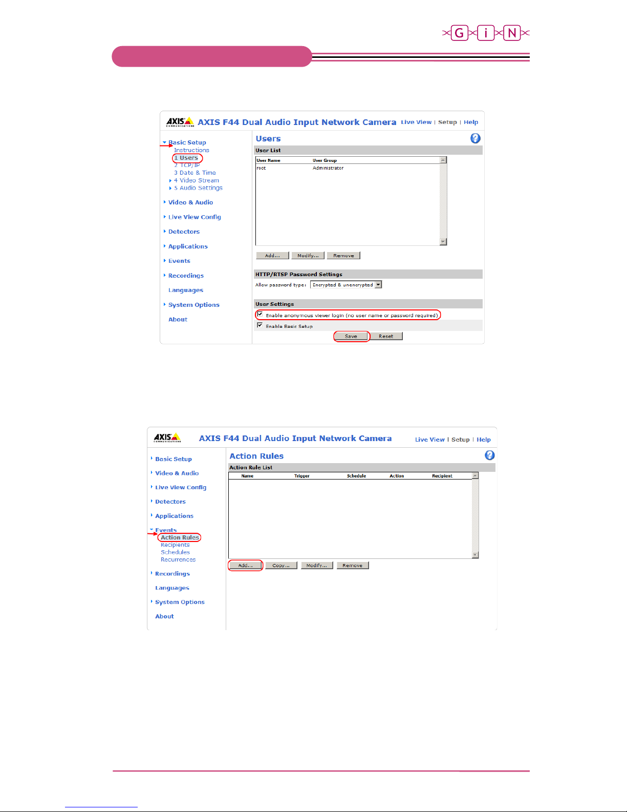
» Activate the option “Enable anonymous viewer login (no user name or password required)” under “Basic
Setup/Users”. To access the FTP server, no user name and password may be entered.
Figure 14
3.5 Action Rules
Under “Event/Action Rules”, previously set rules and conditions for a trigger event are defined in a profile.
To adjust the camera, the specific sensor units must be connected.
Figure 15
Page 18

- 18 -
© G.i.N. GmbH, 2018
Intelligente Datenlogger
Network Camera (HostCAMF44) Manual
Figure 16
Page 19

C
- 19 -
© G.i.N. GmbH, 2018
Intelligente Datenlogger
Network Camera (HostCAMF44) Manual
The following settings are needed in this dialog:
General
» Name: Name of the profile (here Camera1_Sensor1).
Condition
» Trigger: Select “Input Signal” and “Manual Trigger” as a trigger condition for sensor unit 1…4.
» Schedule: No schedule is used for the data logger.
Actions
» Type: Select “Send images” as action (e.g. to the data logger or FTP server).
» Select video source: The same sensor unit as selected under “Trigger” must be designated here too.
» Stream profile: Select one of the profiles for image resolution defined in chap. 3.3.
» Image frequency: Set the image frequency to frames per second, minute, or hour. The maximum
frequency is 25 fps.
» Duration: Set the duration of the recording.
- Pretrigger: Number of seconds to include in the recording from the time immediately before the event.
- While the rule is active: Send images to the FTP server, as long as the trigger event is set. This action
is only used with a significantly lower frame rate and with an average image resolution at most.
- Post-Event time: Number of seconds to include immediately after the event has taken place.
- Send only the first images: Is not used.
Please note that the options "While the rule is active" and "post-event time" must NOT be activated
simultaneously.
» Recipient: Select the data logger FTP server (see chap. 3.4).
» Create folder: This text field must be empty.
» Base file name: File name of an image. The defined name in the screenshot is:
HOSTCAM1_Sensor1_%Y-%m-%d_%H-%M-%S-%f0.jpg.
- “HOSTCAM”: Is necessary as a prefix.
- The value after the prefix is optional and describes the camera number.
- “Sensor” is recommended as a prefix, to distinguish between the sensor units of a camera unit.
- The value after the prefix is optional and describes the sensor unit.
- The attribute “%Y-%m-%d_%H-%M-%S-%f0” indicates the time of recording.
The time specification in this format is defined and prescribed by G.i.N. Additionally, this
requires enabling the option "Overwrite / Use own file format".
When saving the setting with pressing the button “OK”, the following warning is shown:
Figure 17
Page 20

- 20 -
© G.i.N. GmbH, 2018
Intelligente Datenlogger
Network Camera (HostCAMF44) Manual
This warning can be ignored by pressing the button “OK”.
3.6 Changing Capture Mode
The settings of the capture mode for the specific sensor unit can be changed under “Video and
Audio“/Camera 1…4/Settings“.
Figure 18
Please note that every change of the capture mode for a sensor unit leads to a reset or deletion of the
following settings:
» Exposure window
» Image overlays
» Motion detection window
» Privacy masks
Furthermore, it is highly recommended to adjust the frame rate in the action rules
to the selected capture
mode (see chap. 3.5)
Page 21

C
- 21 -
© G.i.N. GmbH, 2018
Intelligente Datenlogger
Network Camera (HostCAMF44) Manual
4 Installing Activation License
To operate the HostCAMF44 in connection with the G.i.N data logger, a data logger based or camera-based
HostCAM license is required.
The data logger based HostCAM license allows to operate the cameras (with or without a camera-based
license).
If no data logger based HostCAM license is installed on the data logger, each connected camera must have
a camera-based HostCAM license.
The activation license has the file extension “*.LIC”. The data logger distinguishes between lower and
upper case regarding the license file name. P
lease make sure that the file extension only contains upper
case letters.
4.1 Data Logger Based HostCAM License
The acquired HostCAM license (in a *.LIC file) can be installed on the device using GiNconf via the menu
item "Options | Install license".
The following example shows the structure of the file name and its meaning:
20170802-002_2840_A4.LIC
Serial number of the data logger
20170802-002
Data logger type (GL53xx)
2840
License type (HostCAMF)
A4
4.2 Camera-based HostCAM License
Please verify if the minimum requirements are met for installing the HostCAM license and the operation
alongside the G.i.N. data logger.
Software/Hardware
Version
Network-Camera
(HostCAMF44)
Firmware version 6.50.2.3
GL53xx
Firmware version 0.57
The following example shows the structure of the license file name and its meaning:
00408CEC0F2B_CAA1_FF.LIC
Camera serial number
00408CEC0F2B
Device type (Network-Camera)
CAA1
License type (Network-Camera)
FF
To install the acquired HostCAM license on the camera, please proceed as follows:
» Press the button “System Options/Advanced/File Upload”.
Page 22

- 22 -
© G.i.N. GmbH, 2018
Intelligente Datenlogger
Network Camera (HostCAMF44) Manual
Figure 19
The "User level" setting must not be changed (default: Viewer).
» Press the button “Browse…” and select the *.LIC file. The name of this file contains the serial number of
the camera.
Figure 20
» Press the button “Upload“.
» The successfully uploaded license file will then appear in the bottom under "Remove Uploaded Files".
Rebooting the camera is not necessary.
Page 23

C
- 23 -
© G.i.N. GmbH, 2018
Intelligente Datenlogger
Network Camera (HostCAMF44) Manual
Figure 21
To remove this file, check the appropriate box and then press the button "Remove".
4.3 Information about Installed HostCAM Licenses
The information about the installed HostCAM licenses is included in the "ml_rt2.ini" file. This is generated by
the data logger in the root directory of the external storage medium.
If a data logger based HostCAM license (i.e. globally for all network cameras) is present, the following is
entered in the *.INI file:
HostCam1Enabled=1
HostCam2Enabled=1
HostCam3Enabled=1
HostCam4Enabled=1
HostCam5Enabled=1
HostCam6Enabled=1
HostCam7Enabled=1
HostCam8Enabled=1
HostCam9Enabled=1
The following is entered in the *.INI file if no global data logger based HostCAM license is available, and only
camera no. 1 with 4 connected sensor units has a camera-based HostCAM license with the shown serial
number:
HostCam1SerNum=ACCC8E37E566
HostCam2Enabled=1
HostCam2SerNum=ACCC8E37E566
HostCam3Enabled=1
HostCam3SerNum=ACCC8E37E566
HostCam4Enabled=1
HostCam4SerNum=ACCC8E37E566
HostCam5Enabled=0
HostCam6Enabled=0
HostCam7Enabled=0
HostCam8Enabled=0
HostCam9Enabled=0
Page 24

- 24 -
© G.i.N. GmbH, 2018
Intelligente Datenlogger
Network Camera (HostCAMF44) Manual
If no license is installed (neither data logger nor camera-based), the following is entered in the *.INI file:
HostCam1Enabled=0
HostCam2Enabled=0
HostCam3Enabled=0
HostCam4Enabled=0
HostCam5Enabled=0
HostCam6Enabled=0
HostCam7Enabled=0
HostCam8Enabled=0
HostCam9Enabled=0
The information about installed HostCAM licenses are displayed with GiNconf via the menu item
"Options | Display device licenses".
Page 25

C
- 25 -
© G.i.N. GmbH, 2018
Intelligente Datenlogger
Network Camera (HostCAMF44) Manual
5 Camera IP Address in the Data Logger System
The camera IP addresses must be known to the data logger to provide communication and image data
transfer.
The camera IP addresses can be entered using LTL or GLWebDisplay.
5.1 Enter or Change IP Addresses via LTL
Chapter 6 describes how to enter or change the IP addresses in LTL.
5.2 Enter or Change IP Addresses via GLWebDisplay
Work in Progress.
Page 26

- 26 -
© G.i.N. GmbH, 2018
Intelligente Datenlogger
Network Camera (HostCAMF44) Manual
6 LTL Control
The data logger provides two functions to communicate with the Network Camera (HostCAMF44):
1. The data logger can send a trigger to the camera.
2. The camera can stores the images via FTP protocol in the data logger FTP server (see chap. 3.4).
» The IP addresses should be entered in the data logger system using the system constants
HostCameraAddress, … HostCamera9Address.
» The type of the connected camera is defined by the system constant HostCameraType, …
HostCamera9Type (default value = 1). The value “2” is set for HostCAMF44 and “1” for HostCAM.
» The number of connected sensor units to HostCAMF44 is set with the system constant
HostCameraParam, … HostCamera9Param. The definition of this system constant is only necessary if
HostCAMF44 is set as HostCameraxType.
SYSTEM
HostCameraAddress = "192.168.9.90" { default = ""}
HostCameraType = 2 { =1 for HostCAM; =2 for HostCAMF44; =0 default}
HostCameraParam = 1 { No. of sensor unit, between 1…4 }
HostCamera2Address =
"192.168.9.90" { default = ""}
HostCamera2Type = 2 { =1 for HostCAM; =2 for HostCAMF44; default=0 }
HostCamera2Param = 2 { No. of sensor unit, between 1…4 }
HostCamera3Address =
"192.168.9.90" { default = ""}
HostCamera3Type = 2
{ =1 for HostCAM; =2 for HostCAMF44; default=0 }
HostCamera3Param = 3 { No. of sensor unit, between 1…4 }
HostCamera4Address =
"192.168.9.90" { default = ""}
HostCamera4Type = 2
{ =1 for HostCAM; =2 for HostCAMF44; default=0 }
HostCamera4Param = 4 { No. of sensor unit, between 1…4 }
…
Sending a trigger to the camera happens in LTL via the predefined variables HostCameraTrigger, …
HostCamera8Trigger. They can be set with CALC. With
CALC
HostCameraTrigger = (1) { For camera1 }
HostCamera2Trigger = (1) { For camera2 }
…
HostCamera8Trigger = (1) { Optional; for camera8 }
The trigger event is set and must be reset with
CALC
HostCameraTrigger = (0) { For camera1 }
HostCamera2Trigger = (0) { For camera2 }
…
HostCamera8Trigger = (0) { Optional; for camera8 }
to be ready for a new trigger event.
The status of a camera can be queried separately using the system variables HostCameraStatus, …
HostCamera8Status. They can have the following values:
Value
Description
1
There is a problem with the camera
2
Camera is online.
0xF1
No license for this particular camera.
The query of the status refers to the control unit and not singular sensor units. The result is independent of
whether the sensor units are connected or not.
Page 27

C
- 27 -
© G.i.N. GmbH, 2018
Intelligente Datenlogger
Network Camera (HostCAMF44) Manual
For example;
SYSTEM
HostCameraAddress = "192.168.9.90"
HostCameraType = 2
HostCameraParam = 1
OUTPUT
LED1 = (HostCameraStatus = 0xF1) { License missing }
LED2 = (HostCameraStatus.0) { Camera error }
LED3 = (HostCameraStatus.1) { Camera online/ready }
Here, LED1 remains off when a HostCAMF44 license (data logger or camera1 based) is available. LED2
flashes when the camera has a problem and LED3 flashes when the camera is ready for use.
» During the image transmit, the simultaneous triggering of multiple cameras can lead to a delayed
storing of data from the triggered data logger storage/ring buffer to the external storage medium.
This
can lead to a temporary stop of bus data recording.
» During an image transfer, no further triggers are received and evaluated by the data logger.
» Please do not trigger the Network Camera (HostCAMF44) in very short intervals.
The time interval
between two trigger events should
be at least large enough for the pictures from the last trigger to be
completely transmitted.
» If at least one camera is transferring images to the data logger can be seen by using the system variable
HostCameraStoring.
» The transmitted camera images are saved in a zip file in the external storage medium of the data logger.
The maximum size of a zip file can be set through the system constant HostCameraPackMaxMBs, with
a value between 10 and 100 MB (default: 250 MB). If the system constant is set to e.g. 10 MB and the
camera transmits images with a total size of 35 MB each trigger, they will be distributed between 4 zip
files.
To display the recorded images in LogGraph (see LogGraph-Manual) it is necessary to record the system
date and time of the data logger. With
EVENT
ON CYCLE (1000) BEGIN
TRANSMIT CAN16 DATA 2000 [year month day hour minute second] LOG ONLY
END
the system date and time are recorded every second in the CAN message with the ID 2000.
Since LogGraph works with the signal-based MDF format, a data base is required for this message. It can be
generated when compiling by activating the option "- T Create CANdbs for all Transmits" under the Compiler
options (see also GiNconf manual, Chapter compiler functions).
Depending on the camera setup (see chap. 3) it will transmit the image files to the data logger FTP server
after receiving the trigger. The images are stored in a zip file in the log folder of the SSD. The name of the
zip file is derived from the name of the latest image of the trigger. For example, images of a trigger with
these names:
HOSTCAM1_Sensor3_2014-07-25_16-51-46-460.jpg
HOSTCAM1_Sensor3_2014-07-25_16-51-47-461.jpg
…
HOSTCAM1_Sensor3_2014-07-25_16-51-56-465.jpg
Are stored in the zip file:
HOSTCAM1_Sensor3_2014-07-25_16-51-46-460.jpg.zip
To view the camera images in LogGraph, it is not necessary to extract the zip files.
Page 28

- 28 -
© G.i.N. GmbH, 2018
Intelligente Datenlogger
Network Camera (HostCAMF44) Manual
The following configuration example defines the triggering of 2 Network Cameras on the GL53xx:
» IP addresses of the two cameras are entered.
» PanelKey1 controls the trigger of sensor unit 1 on camera 1.
» The same for PanelKey2/3/4, they control the triggering of the sensor unit 2/3/4 on camera 1.
» LEDs 1 to 4 indicate the states of the 4 triggers, LED5 flashes permanently.
» The logger display shows the actual amount of the requested camera triggers.
» Each trigger status change is logged in CAN16.
» The data logger enters sleep mode only if Key2 is pressed down for 3 seconds.
SYSTEM
Pause = 0
SleepSeconds = 0
logger1size = 10000
logger2size = 50
AutoConnectAnaIn = 0
StandardDelay = 0
HostCameraAddress = "192.168.9.90"
HostCameraType = 2
HostCameraParam = 1
HostCamera2Address =
"192.168.9.90"
HostCamera2Type = 2
HostCamera2Param = 2
HostCamera3Address = "192.168.9.90"
HostCamera3type = 2
HostCamera3Param = 3
HostCamera4Address =
"192.168.9.90"
HostCamera4Type = 2
HostCamera4Param = 4
TIMER
LongKey2 TIME = 3000 (Key2) { key2 is pressed for 3 seconds }
CALC
SystemRequest = ShutdownRequest WHEN (LongKey2) { request logger shutdown}
CONST
Action_HandleTrigger = 1
Action_SendStatus = 2
VAR
Shutdowntrigger = FREE [1]
TriggerAnzahl = FREE [16]
Action = FREE [8] { for ON CALC handler ... }
FLAG
TriggerFlag1 SET = (PanelKey1) RESET=(NOT PanelKey1) SOUND (HI)
TriggerFlag2 SET = (PanelKey2) RESET=(NOT PanelKey2) SOUND (LO)
TriggerFlag3 SET = (PanelKey3) RESET=(NOT PanelKey3) SOUND (HI)
TriggerFlag4 SET = (PanelKey4) RESET=(NOT PanelKey4) SOUND (LO)
Page 29

C
- 29 -
© G.i.N. GmbH, 2018
Intelligente Datenlogger
Network Camera (HostCAMF44) Manual
EVENT
ON SYSTEM (Startup) BEGIN
TRANSMIT CAN16 DATA 2001 [year month day hour minute second] LOG ONLY
CALC HostCameraTrigger = (Off)
HostCamera2Trigger = (Off)
HostCamera3Trigger = (Off)
HostCamera4Trigger = (Off)
END
ON SYSTEM (Shutdown) BEGIN
TRANSMIT CAN16 DATA 2001 [year month day hour minute second] LOG ONLY
CALC Shutdowntrigger = (1)
END
ON CALC (Action = Action_SendStatus)
ON CALC (Action = Action_HandleTrigger) BEGIN
CALC TriggerAnzahl = TriggerAnzahl + 1
WHEN (Action= Action_HandleTrigger)
TRANSMIT CAN16 DATA 2002 [year month day hour minute second TriggerFlag1
TriggerFlag2 TriggerFlag3 TriggerFlag4] LOG ONLY
END
ON SET (TriggerFlag1) BEGIN
CALC HostCameraTrigger = (On)
Action = Action_HandleTrigger
END
ON SET (TriggerFlag2) BEGIN
CALC HostCamera2Trigger = (On)
Action = Action_HandleTrigger
END
ON RESET (TriggerFlag1) BEGIN
CALC HostCameraTrigger = (Off)
Action = Action_SendStatus
END
ON RESET (TriggerFlag2) BEGIN
CALC HostCamera2Trigger = (Off)
Action = Action_SendStatus
END
ON SET (TriggerFlag3) BEGIN
CALC HostCamera3Trigger = (On)
Action = Action_HandleTrigger
END
ON SET (TriggerFlag4) BEGIN
CALC HostCamera4Trigger = (On)
Action = Action_HandleTrigger
END
ON RESET (TriggerFlag3) BEGIN
CALC HostCamera3Trigger = (Off)
Action = Action_SendStatus
END
ON RESET (TriggerFlag4) BEGIN
CALC HostCamera4Trigger = (Off)
Action = Action_SendStatus
END
ON CYCLE (1000) BEGIN
DISPLAY print (0, "Trig%4d", TriggerAnzahl)
END
ON CYCLE (1000) BEGIN
TRANSMIT CAN16 DATA 2000 [year month day hour minute second] LOG ONLY
END
STOP 1 (LoggerAtEnd) OR (Shutdowntrigger)
START 1 (NOT LoggerAtEnd AND NOT Shutdowntrigger AND NOT FlashFull)
OUTPUT
Page 30

- 30 -
© G.i.N. GmbH, 2018
Intelligente Datenlogger
Network Camera (HostCAMF44) Manual
LED1 = (TriggerFlag1) LED2 = (TriggerFlag2)
LED3 = (TriggerFlag3) LED4 = (TriggerFlag4)
LED5 = (_10msec > 50)
END
6.1 Permanent Recording of Camera Images
During a measurement with the data logger, the HostCAMF44 makes it possible to record images
permanently and to transmit them to the data logger. For this,
» Image resolution (see chap.3.3) and frame rate (see chap. 3.5) have to be set low enough
» The action “Pretrigger” must be deactivated resp. set to 0.
» The action “While the rule is active” must be active (see chap. 3.5).
» The action “Post-event time” must be deactivated resp. set to 0.
The following example shows how a permanent recording with HostCAMF44 with two sensor units in
connection with the G.i.N. data logger is possible:
LTL excerpt for controlling the camera
SYSTEM
HostCameraAddress = "192.168.9.90"
HostCameraType = 2
HostCameraParam = 2
HostCamera2Address = "192.168.9.90"
HostCamera2Type = 2
HostCamera2Param = 2
VAR
CamSwitch = FREE[1]
FLAG
CamRecord = (HostCameraStatus.1 AND CamSwitch)
EVENT
ON SET (Key1) BEGIN
CALC CamSwitch = (NOT CamSwitch)
END
ON SET (CamRecord)
ON RESET (CamRecord) BEGIN
CALC HostCameraTrigger = (CamRecord)
HostCamera2Trigger = (CamRecord)
END
ON SYSTEM (Shutdown) BEGIN
CALC CamSwitch = (0)
END
OUTPUT
LED1 = (CamSwitch)
LED2 = (CamRecord)
» The data logger triggers the camera immediately when it comes online (“HostCameraStatus.1 = 1”) and
keeps the trigger active until shutdown.
» If the camera is not connected anymore (“HostCameraStatus.1 = 0”), the data logger resets the trigger
with “HostCameraTrigger = Off”. As soon as the camera is online, the data logger triggers it again. This
functionality helps to transmit the camera data in the case of a short interruption.
» For every measurement (without interruption), a zip file with the transmitted images is stored in the root
directory of the external storage medium.
» The camera trigger is set and reset with key1
Page 31

C
- 31 -
© G.i.N. GmbH, 2018
Intelligente Datenlogger
Network Camera (HostCAMF44) Manual
» Key1 is used in LTL, for interactive triggering of the camera, as follows: single press of key1 triggers the
camera (sets “CamSwitch” to 1). Pressing it again resets the trigger (set “CamSwitch” to 0) and stops the
image transmit.
» Shutdown of the data logger resets the camera trigger (“HostCameraTrigger = Off”).
» LED 1 shows the status of the switch “CamSwitch” , controlled via key1.
» LED 2 shows whether the camera trigger is set or reset.
Camera settings
In addition to the previous settings of the camera (see chap. 3.5):
Figure 22
Page 32

- 32 -
© G.i.N. GmbH, 2018
Intelligente Datenlogger
Network Camera (HostCAMF44) Manual
» Frame rate of e.g. 1 fps.
» Pretrigger and post-event time are 0s.
Page 33

C
- 33 -
© G.i.N. GmbH, 2018
Intelligente Datenlogger
Network Camera (HostCAMF44) Manual
7 Change History
Date
Reference
Description
08.2018
First version
10.2018
Editorial correction
 Loading...