

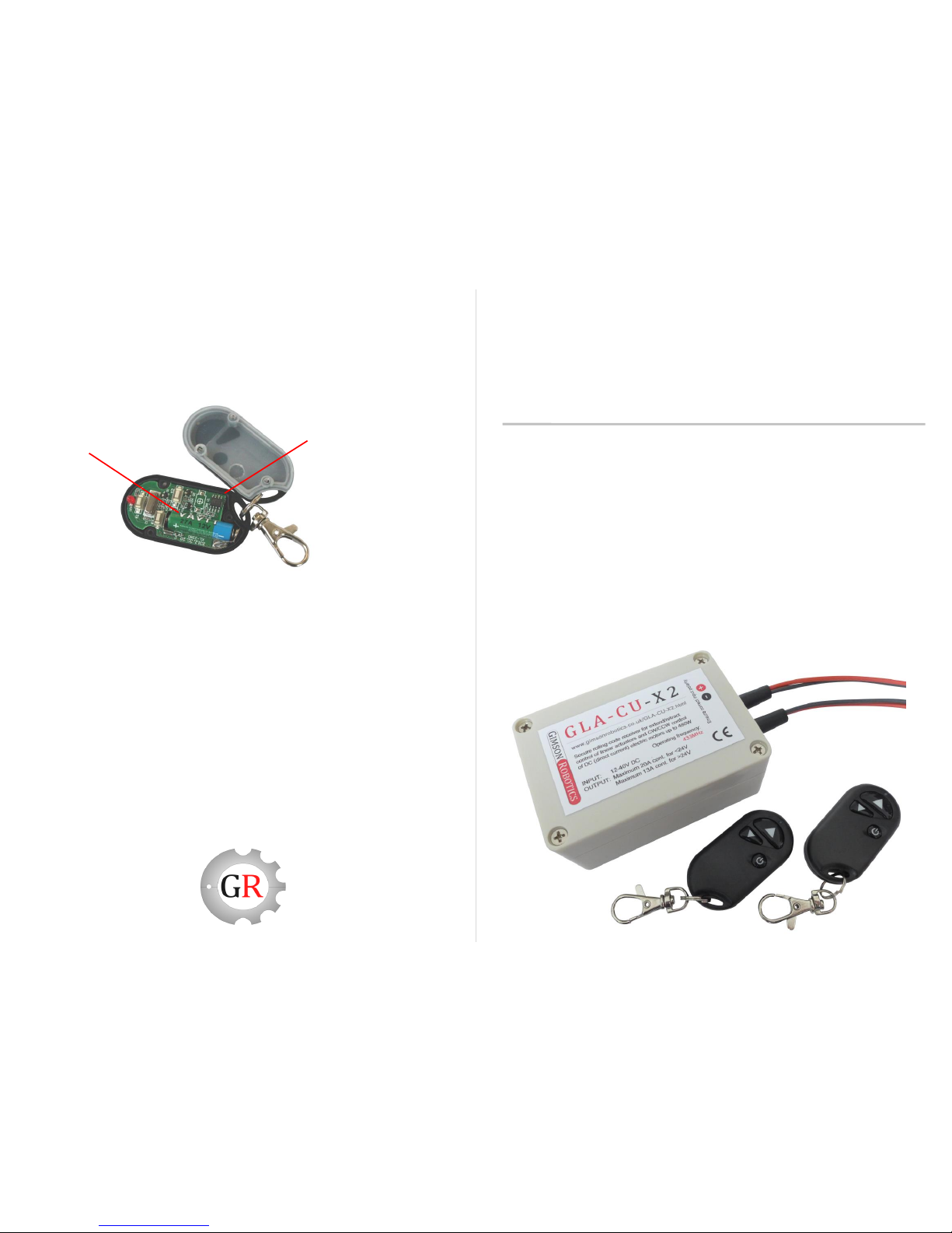
1. Each GLA-CU-X2 unit is supplied with two small ‘keyfob’ transmitters (the
items labelled #2 in the below image) and a rectangular receiver unit (item
labelled #1). The remote transmitter is able to send encrypted instructions to the
receiver which then decodes them and switches a connected actuator or DC
motor in either one direction, the opposite direction, or off.
To get started you should connect the two input leads (those with a white tag
marked ‘INPUT’) to a DC (direct current) supply between 12V and 36V (absolute
limits 9V to 40V). Ensure that the red lead is connected to the positive (+) of the
supply and that the black lead is connected to negative (-). Each unit is supplied
with the included keyfob remote(s) memorised, meaning that if you press the up
and down buttons after having applied power to the receiver you should hear a
‘clicking’ noise as the internal relay switches are activated. If this is the case you
may skip to section 3 of this guide, otherwise use the ‘learning’ procedure
detailed in section 2.
GLA-CU-X2
Actuator & DC Motor Remote Control Unit
Set-up Guide
01/2016
5. If the working range of the remote transmitter falls and/or the LED on the
remote dims noticeably when a button is pressed, it’s likely the remote battery
is running low. To access and replace the battery (a single cell of type A27,
12V) remove the plastic back cover of the transmitter (via three screws), as
shown below. Ensure the new battery is oriented correctly.
27A 12V Battery
Transmitter with the
rear cover removed
(accessed via three
cross-head screws)
Troubleshooting
If the input supply voltage drops below 9V then the receiver will cease to
function. Ensure that the power supply (or battery) used can handle the
load current and is adequately charged otherwise such a voltage drop
may occur.
If the receiver stops responding to the transmitter it may be out of range or
the transmitter battery may be low, try bringing the transmitter closer to
the receiver and if that doesn’t help try replacing the transmitter battery via
removing its back cover (see section 5). Be aware that the effective
operation range will be reduced significantly by large metal objects
between the transmitter and receiver (as these shield against radio
waves)
Ensure that the input and output leads do not get tugged hard, if this
happens the screw terminals that they are connected to on the control
board may become loose.
For any product issues or questions not covered in this guide please contact us
either by email at support@gimsonrobotics.com
or via the website at www.gimsonrobotics.co.uk/contact.html
#2 Transmitters
#1 Receiver
2. The receiver unit is able to selectively memorise which remote transmitters
to respond to; in this way one remote may control one or multiple receivers, or
one receiver may be controlled by one or multiple remotes (each receiver is
able to memorise up to seven separate remotes). Multiple (>20) remote and
receiver pairs may also be used independently in the same area provided that
they are ‘learned’ separately from one-another.
The procedure for ‘learning’ a remote is as follows:
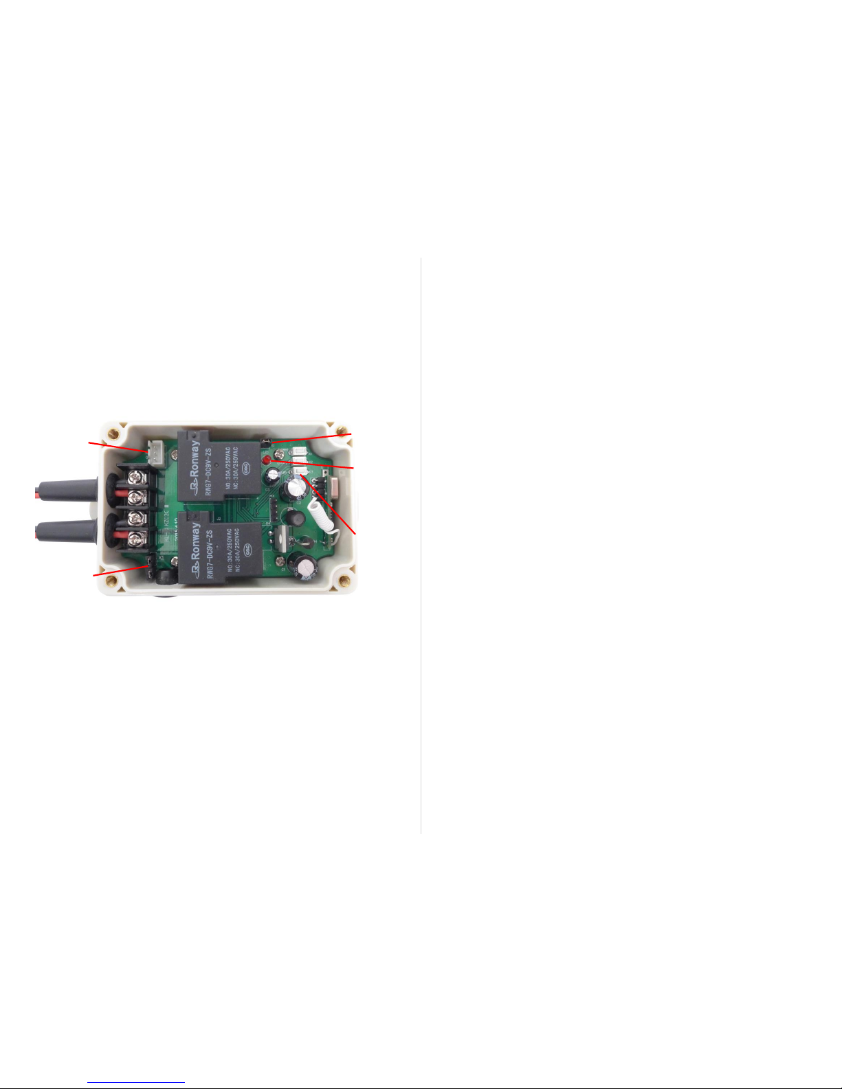
1. Remove the plastic lid from the receiver casing (by removing four cross-head
screws). You should then be able to see three small white push-buttons on the
board labelled UP (K3), STOP (K2) and DOWN (K1), as shown below:
2. Connect the unit INPUT lead to a DC power source between 12-36V, do not have
the OUTPUT connected to a device at this point (and do not allow the ends of the
OUTPUT leads to touch one-another). Be sure not to expose the board to any
metal objects (such as loose screws) while the cover is removed.
3. Check that when you (briefly) press a white push-button the red LED on the board
lights up, if it does then the receiver should be on. Have the remote you wish the
unit to memorise to-hand and then simultaneously press the ‘UP’ button on the
receiver board and the up button on your remote, then release the receiver button
and the LED on the board should start flashing.
4. Repeat step three with the white button labelled STOP and the stop button on the
remote to calibrate this button.
5. Repeat step three with the button DOWN and the down-arrow remote button.
6. The board should now have learned the remote and the next time you press an up
or down button (with the board powered) a relay should 'click' meaning the
controller is switching the output current.
If you wish to reverse the remote operation (so that the travel of the controlled
device is reversed for a given command) then follow the learning steps above
but in the opposite order (UP to remote down button, DOWN to up button).
Learning
Buttons
UP (K3)
STOP (K2)
DOWN (K1)
LED
To erase the memory of previously learnt remotes press and hold any white
button on the board for a long time (around 10 seconds), the red LED should turn
on initially and then after a long pause turn off which signifies that the memory is
now clear, you can then release the button.
3. Using the receiver with a DC motor or actuator is simple, just connect the two
output leads (labelled ‘OUTPUT’) to the two leads of the device to be operated,
then when a DC source is connected to the ‘INPUT’ you should be ready to go.
Pressing the up button on the remote should cause the device to travel in one
direction and pressing the down button should reverse the direction of the output
current and the reverse the motor or actuator travel.
Control modes: Two operating modes may be selected, either Latching (a single
press of a remote leads to a constantly-on output, only turning off when a different
button is pressed) or Momentary (the output will only stay on for as long as a
remote button is held, and the ‘stop’ button becomes redundant). Latching is the
default operating mode, to change to momentary remove the black jumper cap
from position S1 on the receiver board (and keep the jumper safe in case you wish
to change modes back again later).
Wired switch input: A SPDT rocker-switch or two push-buttons may be used to
operate the receiver via the white connector labelled ‘UP, GND, DOWN’. If 'UP'
and 'GND' are connected to one-another then the receiver will change the output to
'UP', if 'DOWN' and 'GND' are connected then the output will change to the
opposite direction. Any wired inputs supplied to the board here will override
instructions given by remote transmitters to the receiver. A lead with three-way
(white plastic) connector is included, to match the connector on the board.
Automatic-off Timer: (applies to units supplied from Feb 2016) The receiver has
an optional timer function (enabled by default), which automatically switches off the
output in latching mode if no new control instruction has been received within 120
seconds. This feature can help to save energy by minimising the time that a relay
is being powered (whereas otherwise the relay would continue to operate until a
‘stop’ button were pressed). To disable the timer remove the black plastic jumper
from the position marked ‘120S’ on the PCB (by the wired-switch input connector).
4. The receiver features inputs for limit switches (if you are using a device with
built-in limit switches or one that does not need them you may disregard this
section). There are four contacts on the board, in two pairs labelled X1 and X2
(bottom-left of diagram in section 2.), these are supplied with two black jumpers
bridging each contact pair but if these jumpers are removed you may put
Normally-Closed switches in their place to serve as limit switches. Each time a
switch were pressed (and went open-circuit) the receiver would prevent the
output from switching in a one direction. In this way you can mount switches on
the device you are controlling that will automatically stop movement when an end
position (as determined by a limit switch trigger position) is reached.
Wired Switch
Inputs
(UP, GND,
DOWN)
Limit Switch
Inputs (X1, X2)
Mode
Selection
Jumper (S1)
 Loading...