

Page 1
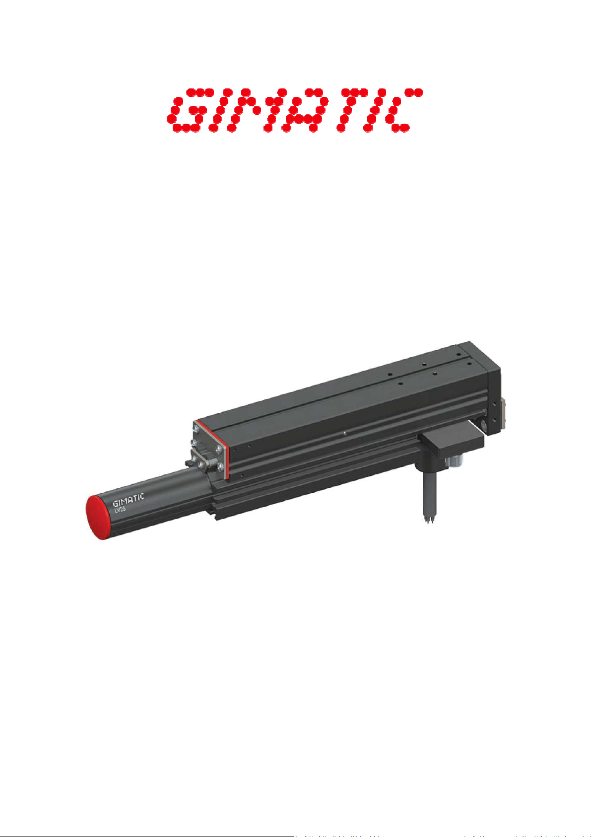
ELECTRIC LINEAR ACTUATORS
LV SERIES
USER GUIDE
Version 2.1
Page 2

Page intentionally left blank
Page 3

TABLE OF CONTENTS
1. SAFETY - General product safety information
1.1. General safety
2. INTRODUCTION - Introduction to this user guide
2.1. About this user guide
2.2. Terms and abbreviations
3. PRODUCT OVERVIEW - About Gimatic's products: features and catalogue number interpretation
3.1. About Gimatic's LV Actuators
3.2. Features
3.3. LV and LVP systems
3.4. LV product range
3.5. Catalogue number interpretation
4. SYSTEM DESIGN - How to design a LV based system for your application
4.1. System components
4.2. Electric linear slides
4.2.1. Application
4.2.2. Slider
4.2.3. Stator
4.2.4. Weight counter balance
4.2.5. Brake
4.2.6. Cable carrier
4.3. Servo drive
4.4. Linear encoder
4.5. Sensors
5. SPECIFICATIONS - Overall characteristics of LV linear slide
5.1. Electrical
5.2. Operative fields
5.3. Static thrusts
5.4. Mechanical
5.5. Safety loads
5.6. Deflection
6. INSTALLATION - Mechanical and electrical configuration
6.1. Unpacking
6.2. Mechanical
6.2.1. Linear encoder
6.2.2. Mounting examples
6.3. Electrical
6.3.1. Motor power and temperature feedback
6.3.2. Sensors
6.3.3. Electromagnetic compatibility (EMC)
Page 4

6.4. Servo drive configuration
7. MAINTENANCE - Suggested activities for systems based on Gimatic's LV products
8. ACCESSORIES - Available accessories
9. APPENDIX - Additional information
9.1. Application continuous force calculation example
9.2. Duty cycle calculation
10. SERVICE ENQUIRIES - Information required for a correct enquiry
10.1. Main Application Data
Page 5
Gimatic
- LV Electric Linear Actuators
www.gimatic.com
Page
1
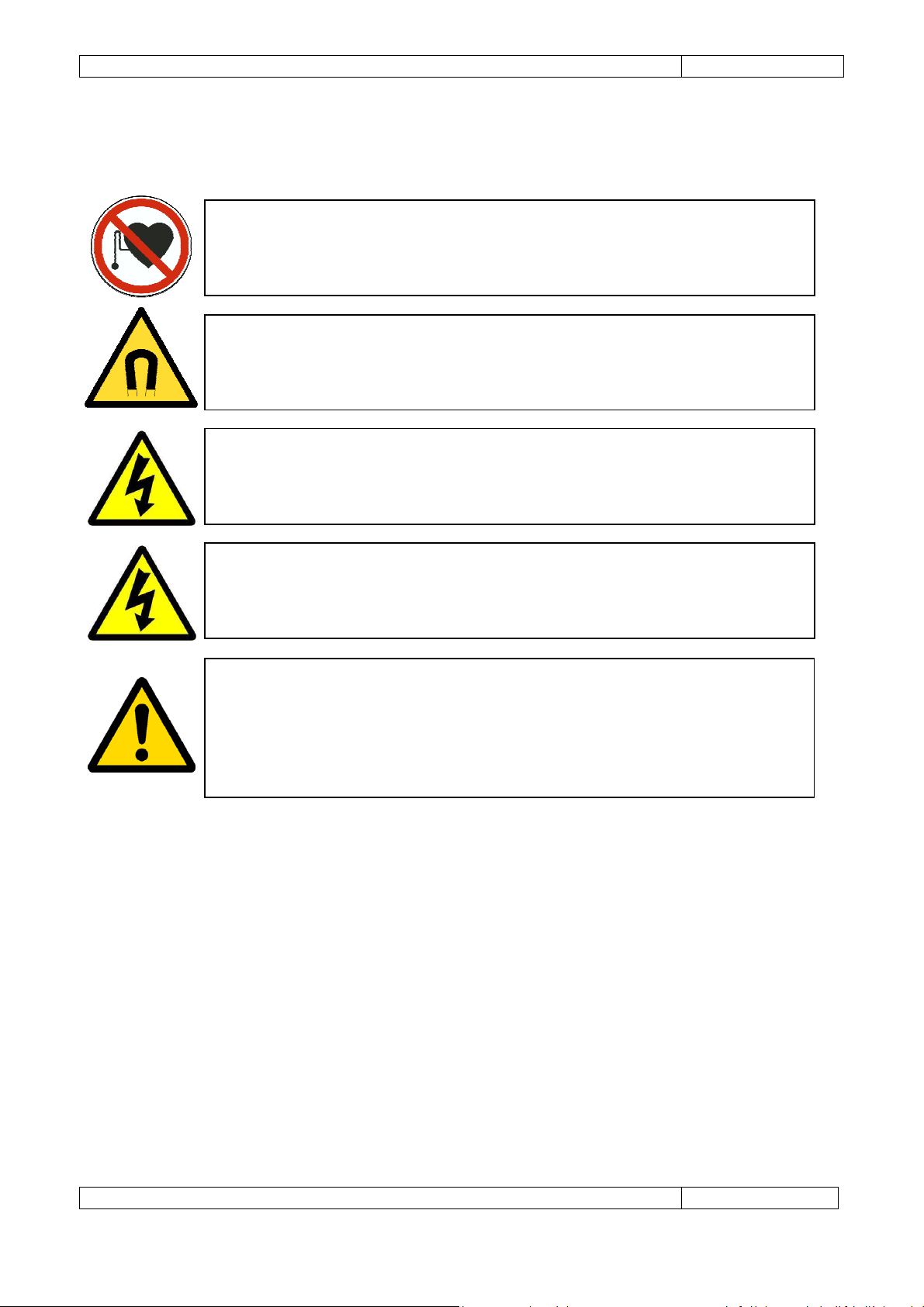
WARNING
: Embedded tubular motor shafts contain powerful permanent magnets.
DANGER HIG
H VOLTAGE
: Ensure the power has been completely disconnected
DANGER HIGH VOLTAGE
: The system must be properly grounded before applying
followed. Electrical shock can cause serious or fatal injury.
WARNING
: The shaft emits a very strong magnetic field. Always use caution when
WARNING
: When embedded temperature sensor (PTC) is employed a t
emperature
1. SAFETY
People with pacemakers, AICD or similar medical devices should maintain a
minimum distance of 30 cm from the shaft.
handling. To avoid injury, keep fingers and other body parts clear.
before touching any electrical connections. Electrical shock can cause serious or
fatal injury.
power. Ensure the system has been grounded according to Section 6.3.1 Motor
power and temperature feedback. National and local electrical codes must be
This manual and the warnings attached to the LV linear slides only highlight hazards that can be predicted
by Gimatic. Be aware they do not cover all possible hazards.
Gimatic shall not be responsible for any accidents caused by the misuse or abuse of the device by the
operator.
Safe operation of these devices is your own responsibility. By taking note of the safety precautions, tips and
warnings in this manual, you can help to ensure your own safety and the safety of those around you.
value of 95 °C must be set as maximum temperature allowed for the stator during
driver’s programming. This is equivalent to the PTC value less or equal to 1330 Ω
(Section 4.5 Sensors). Whenever PTC connection is not possible a proper i2t
parameter has to be set by the user during driver’s programming in order to
preserve ML stator from permanent damaging.
Page 6

Gimatic
- LV Electric Linear Actuators
www.gimatic.com
Page
2
1.1 General safety
The following points must be understood and adhered to at all times:
• Equipment operators must read the User Guide carefully and make sure of the correct procedure
before operating the LV linear actuators.
• Memorize the locations of the power and drive isolator switches so that you can activate them
immediately at any time if required.
• If two or more people are working together, establish signals so that they can communicate to
confirm safety before proceeding to another step.
• Be aware of the closest First Aid station.
• Always make sure there are no obstacles or people near the devices during installation and or
operation. Be aware of your environment and your surroundings.
• Keep the area around LV actuators clean and tidy.
• Take precautions to ensure that your clothing, hair or personal effects (such as jewelry) cannot
become entangled in the equipment.
• Do not turn on any of the equipment without all safety features in place and known to be
functioning correctly. Never remove any covers or guards unless instructed by the procedures
described in this manual.
• Never touch any exposed wiring, connections or fittings while the equipment is in operation.
• Visually check all switches on the operator panel before operating them.
• Do not apply any mechanical force to the LV actuators, which may cause malfunction or failure.
• Never attempt cleaning or inspection when the machine is operating.
• Clean or inspect the equipment only after isolating all power sources.
• Only suitably qualified personnel should install, operate, repair and/or replace this equipment.
• Ensure all external wiring is clearly labeled. This will assist you and your colleagues in identifying
possible electrical safety hazards.
• Use cables with the minimum cross sectional area as specified in the Electrical Connection
specification section of this guide.
• Install cables according to local legislation and regulations as applicable.
• Ensure there are not moving parts of the actuator while in contact with the motor’s electrical
connections. Movement can induce a voltage that could cause an electrical shock.
Page 7
Gimatic
- LV Electric Linear Actuators
www.gimatic.com
Page
3
GND
Ground
rms Root mean square
g Gravity m/s
2
V / mV
Volt / millivolt
A / mA
Ampere / milliampere
Ω ohms
AC / DC
Alternating Current / Direct Current
Hz Hertz
ms millisecond
AICD
Automatic Implantable Cardioverter
-
Defibrillator
EMC
Electromagnetic Compatibility
2 INTRODUCTION
2.1 About this user guide
This user guide provides the required information for planning to install, installation and servicing of the LV
linear slides. It has been written specifically to meet the needs of qualified engineers, tradespersons,
technicians and operators.
2.2 Terms and abbreviations
3 PRODUCT OVERVIEW
3.1 About Gimatic's LV actuators
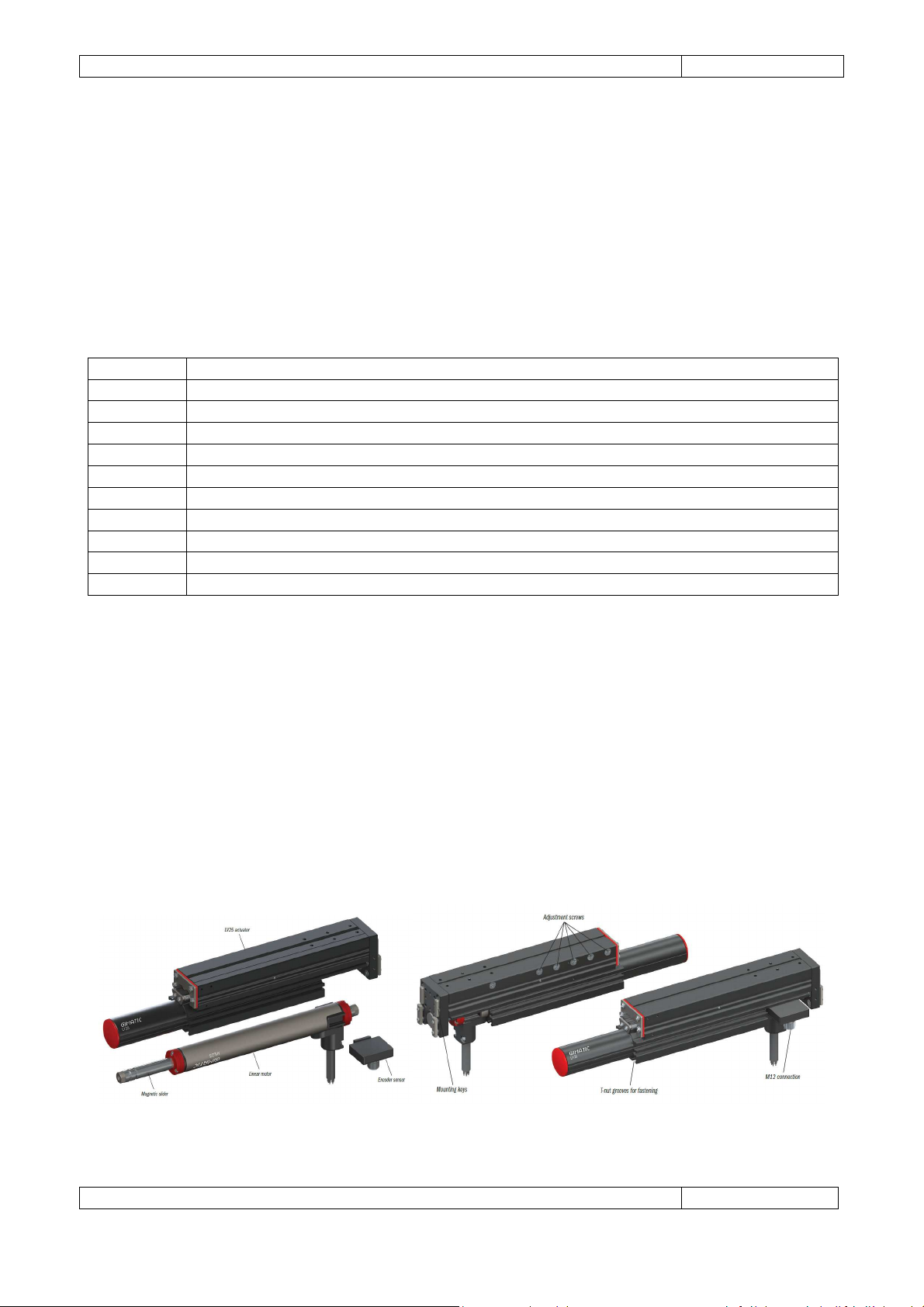
The Gimatic LV actuator is a recirculating ball bearing slide equipped with a 3-phase, brushless, DC,
permanent-magnet motor designed for direct-drive, high-precision and high-dynamics applications. High
efficiency and performance of Gimatic's ML linear motors meet a lightweight aluminium slide which
provides a prismatic guide for the motion of the slider (anti-rotation), a heat dissipation functionality and
high stiffness in several directions. Adjustable preloading screws and long life bearings assure low
installation and maintenance costs.
Page 8
Gimatic
- LV Electric Linear Actuators
www.gimatic.com
Page
4
Y
Z
LVP25
actuator
Magnetic
slider
Linear
motor
En
coder
Adjustment
T-nut grooves
Hardened
M12
3.2 Features
• High continuative force/current.
• Zero backlash – No ball screw or gearbox eliminates backlash.
• High acceleration forces – More than 400 [N] depending on model.
• Low installation and maintenance costs – Simple construction, T-nut grooves for fastening.
• Fully sealed – IP67 rating standard.
• Zero net attractive forces improve efficiency with no down force and extended machine life.
• Durable – Stator materials’ high insulation class results in long motor life. 10 million cycles
maintenance-free.
• Efficient – The extremely strong magnetic flux, cylindrical design and small moving mass provide for
very efficient linear motion.
3.3 LV and LVP systems
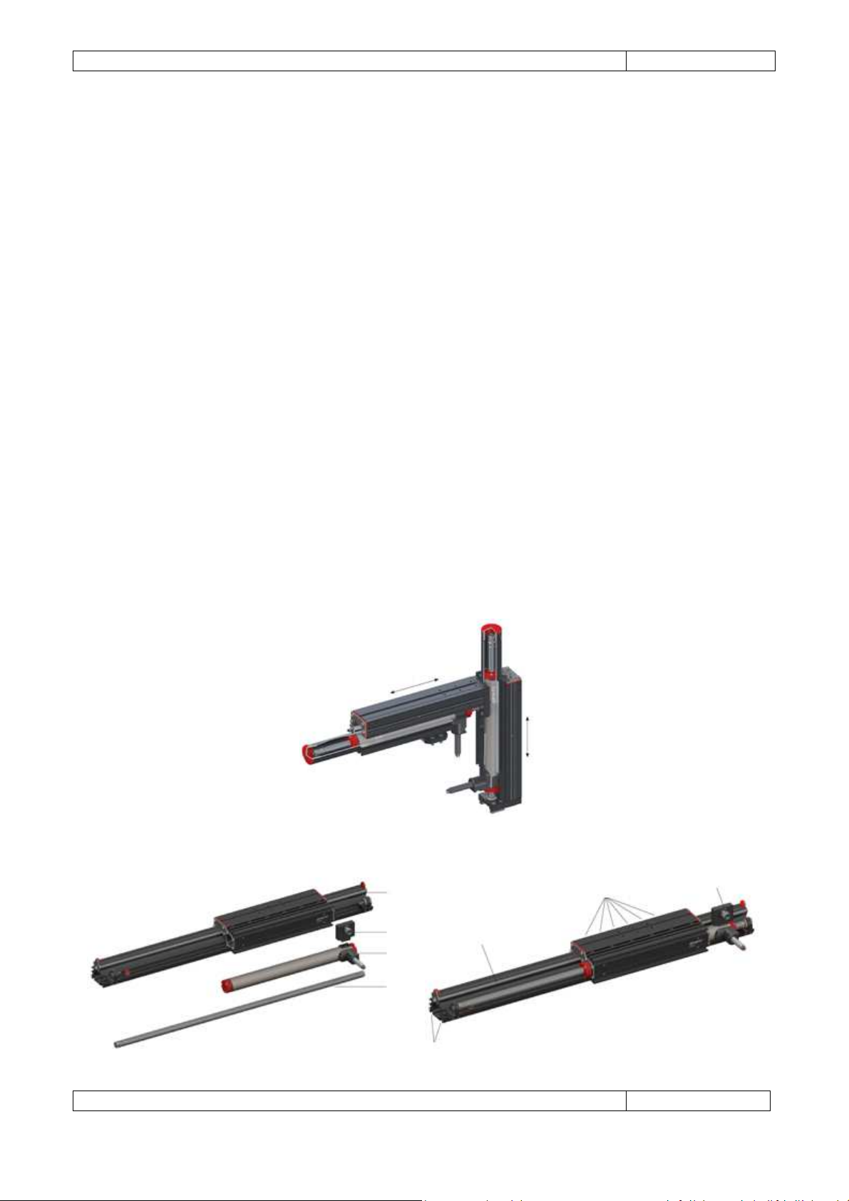
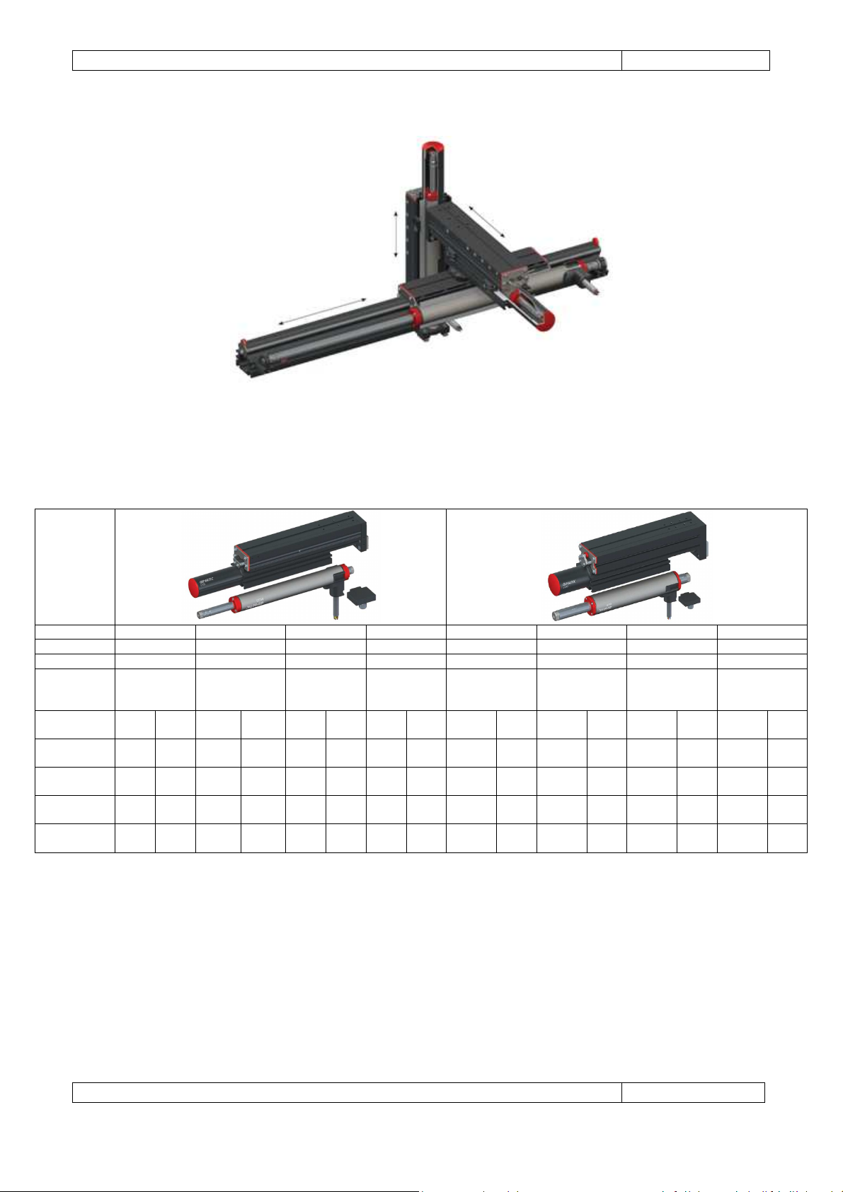
LV actuators can be combined in order to create multiple axis systems. Furthermore for all those
applications requiring longer strokes and/or higher stiffness along the entire stroke, Gimatic linear
actuators are also available as linear guides (LVP25 and LVP40). These guides can be combined with LV
actuators to create more complex structures (i.e. cartesian manipulators).
LV EXAMPLE APPLICATION: 2 AXIS PICK&PLACE SYSTEM
LVP SYSTEM STRUCTURE
steel bars
for fastening
screws
connection
Page 9
Gimatic
- LV Electric Linear Actuators
www.gimatic.com
Page
5
LV25050
LV25100
LV25150
LV25
200 LV40050
LV40100
LV40150
LV40200
Stroke [mm]
50
100 150 200 50 100 150 200
Total mass [g]
1170 1380 1825 2185 2730 3590 4430 4865
Mass of parts
BUS voltage
Peak current
Continuative
Peak force
Continuative
X
Y
Z
LVP+LV EXAMPLE APPLICATION: 3 AXIS PICK&PLACE SYSTEM
3.4 LV product range
fixed to the
slider [g]
[Vdc] (peak)
[A]
current [A]
[N]
force [N]
560 670 850 1050 1350 1840 2150 2420
72 325 72 325 72 325 72 325 72 325 72 325 72 325 72 325
7.87 3.49 7.87 3.49 5.42 2.07 5.42 2.07 19.85 8.79 19.85 8.79 15.46 6.19 15.46 6.19
1.57 0.49 1.57 0.49 1.48 0.48 1.48 0.48 3.09 0.94 3.09 0.94 3.38 0.98 3.38 0.98
100 120 100 120 110 130 110 130 270 420 270 420 320 440 320 440
20 17 20 17 30 30 30 30 42 45 42 45 70 70 70 70
Page 10
Gimatic
- LV Electric Linear Actuators
www.gimatic.com
Page
6
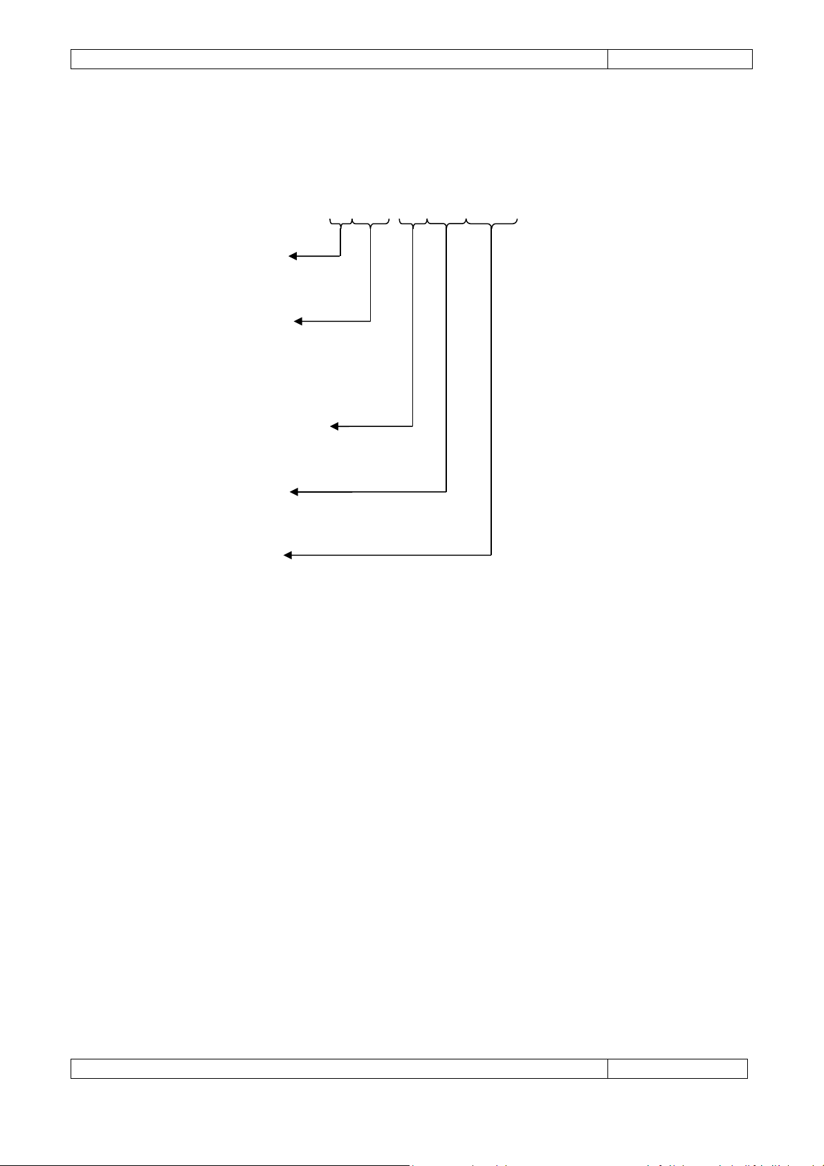
3.5 Catalogue number interpretation
Electric linear slide: ordering code example
LV25050-70ABZHALL
Motor's size: 25 [mm]
40 [mm]
Stroke: 050 [mm]
100 [mm]
150 [mm]
200 [mm]
BUS voltage: 70 (72 [V] peak)
300 (325 [V] peak)
Feedback: - (none)
ABZ (incremental encoder)
SIN (SIN/COS analog output) *
Phase sensor: - (none)
HALL (Hall sensors)
(*) Under development.
4 SYSTEM DESIGN
4.1 System components
The design of the LV linear slide allows for simple installation in any custom application, however to achieve
the best performance the final system must be optimized. This chapter describes the main components to
consider when designing such a system.
The primary components of LV systems based are:
1. Cable carrier
2. Servo drive
3. Linear position transducer (encoder)
Additionally the following secondary components may be required depending on the application:
4. Home and End-stop sensors
5. Mechanical over stroke limitation
6. Weight counter balance device (for vertical applications)
7. Brake
Page 11
Gimatic
- LV Electric Linear Actuators
www.gimatic.com
Page
7
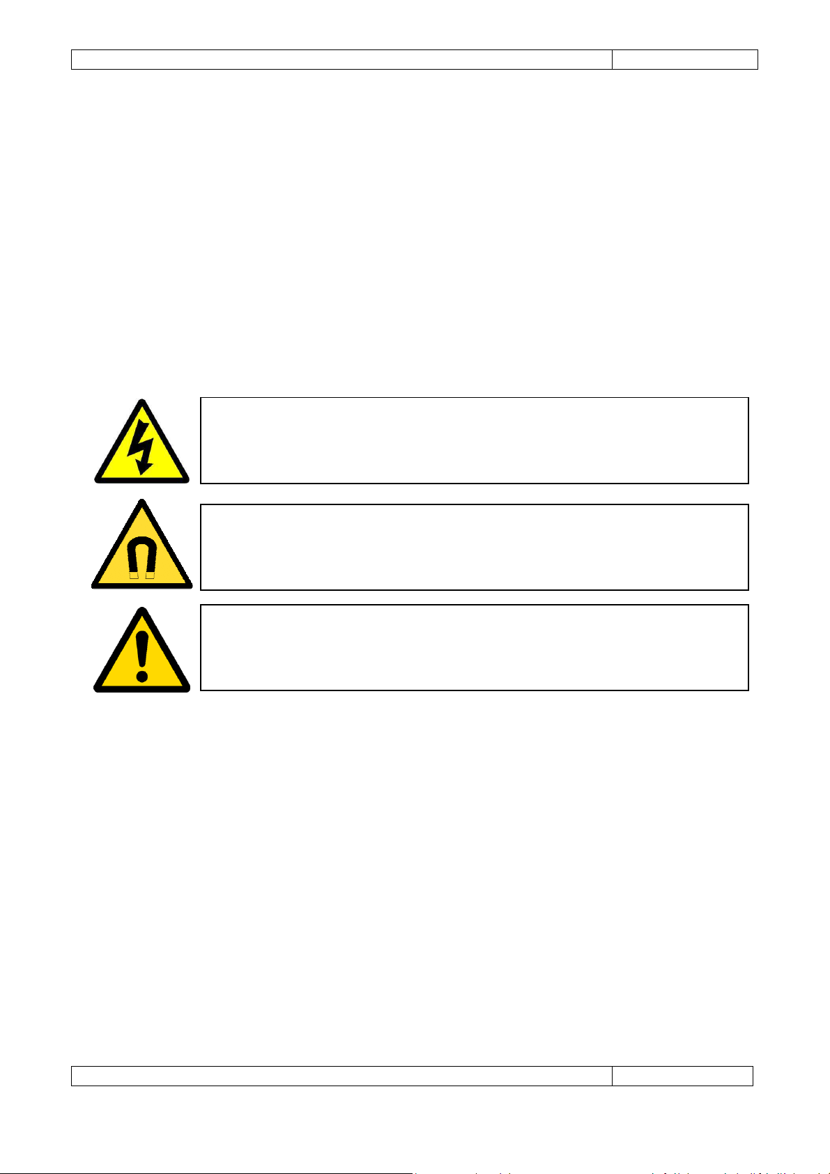
DANGER
: LV slide integrates a magnetic shaft that must be grounded to prevent the
WARNING
: The sh
aft emits a very strong magnetic field. Always use caution when
WARNING:
Interaction around the shaft must be carefully considered. Ensure
4.2 Electric linear slides
4.2.1 Application
A LV linear actuator is based on a tubular linear motor that provides relative motion between the slider and
the stator. In a single axis system the LV part hosting the motor's stator is typically fixed to an external
frame while the slide hosting the motor's slider interacts with the load (directly or by means of gripper or
some other tools). In multiple axis systems, several LV actuators can be connected in series to create
cartesian robotic arms or more complex architectures. The LV slide can be mounted horizontally, vertically
or any angle in between.
4.2.2 Slider
possibility of electric shock during actuator operation.
The strong magnetic nature of the embedded slider must be considered in the final machine design. Care
should be taken with its proximity to magnetic materials and sensitive parts. It is recommended that nonmagnetic material be used in the system wherever possible. If magnetic material is required, ensure it is at
sufficient distance from the slider so that it is unaffected. The slider’s performance can be reduced if
subjected to temperatures above 100 °C. Therefore, consideration must be given to the slider’s operating
environment and the continuous operating current of the application for the expected ambient
temperature.
handling. To avoid injury, keep fingers and other body parts clear.
appropriate warnings and/or guards are installed to prevent damage to the machine
or operator.
4.2.3 Stator
LV model selection is primary dependent upon the peak force, continuous force and peak velocity. These
specifications depend on the embedded motor's stator and they need to be identified before ordering a LV
system.
• Peak Force – Identify the peak force required for the application. An electric actuator will only be
able to produce its peak force for a short period of time; the duty cycle also needs to be
considered.
Page 12
Gimatic
- LV Electric Linear Actuators
www.gimatic.com
Page
8
Linear actuator
LV25050
LV25100
LV25150
LV25200
Length [mm]
187 227 284 339
Total mass [g]
105 136 165 191
Stroke [mm]
50
100 150 200
Stiffness [N/m]
100
DANGER:
T
he
stator
must be
grounded via the proper cable to prevent the possibility
WARNING:
Cooling of the stator must be considered for applications with a high
• Continuous Force – Identify the RMS force usage of the application. An electric actuator is able to
exceed its continuous force rating by an amount depending on the duty cycle. Exceeding this can
result in exceeding the motor temperature ratings and damage to the motor. Refer to the
Application continuous force calculation example for more information on how to calculate an
application's continuous force requirement.
• Peak Velocity – Identify the peak velocity required for the application. Available peak force may be
reliant on velocity depending on the DC Bus voltage of the servo drive and the LV model chosen.
Refer to Operative fields section of this guide which summarizes performances of motors
themselves. Despite motors can reach very high speed (several m/s), 10 million cycles
maintenance-free operations of LV actuators are guaranteed for movement speed of up to 2 m/s.
continuous operating current.
of electric shock during motor operation.
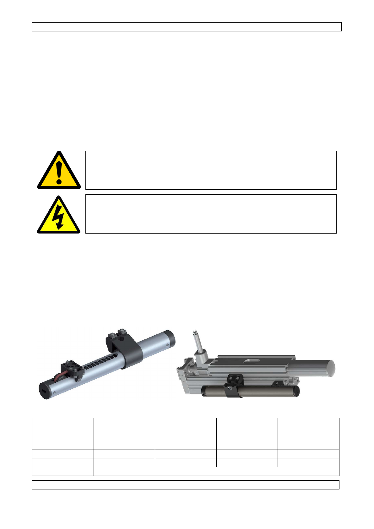
4.2.4 Weight counter balance
In vertical applications where a counter-balance is not used, the actuator must constantly produce a force
directly opposing gravity. This adds to the application continuous force requirements and, therefore,
influences the motor model selection. A counter balance device should be considered in order to
compensate the load statically. Gimatic manufactures a spring compensator that can be mounted laterally
on LV devices. A brake is recommended for most applications but must be used to prevent damage in
applications where the load drops immediately after power is removed.
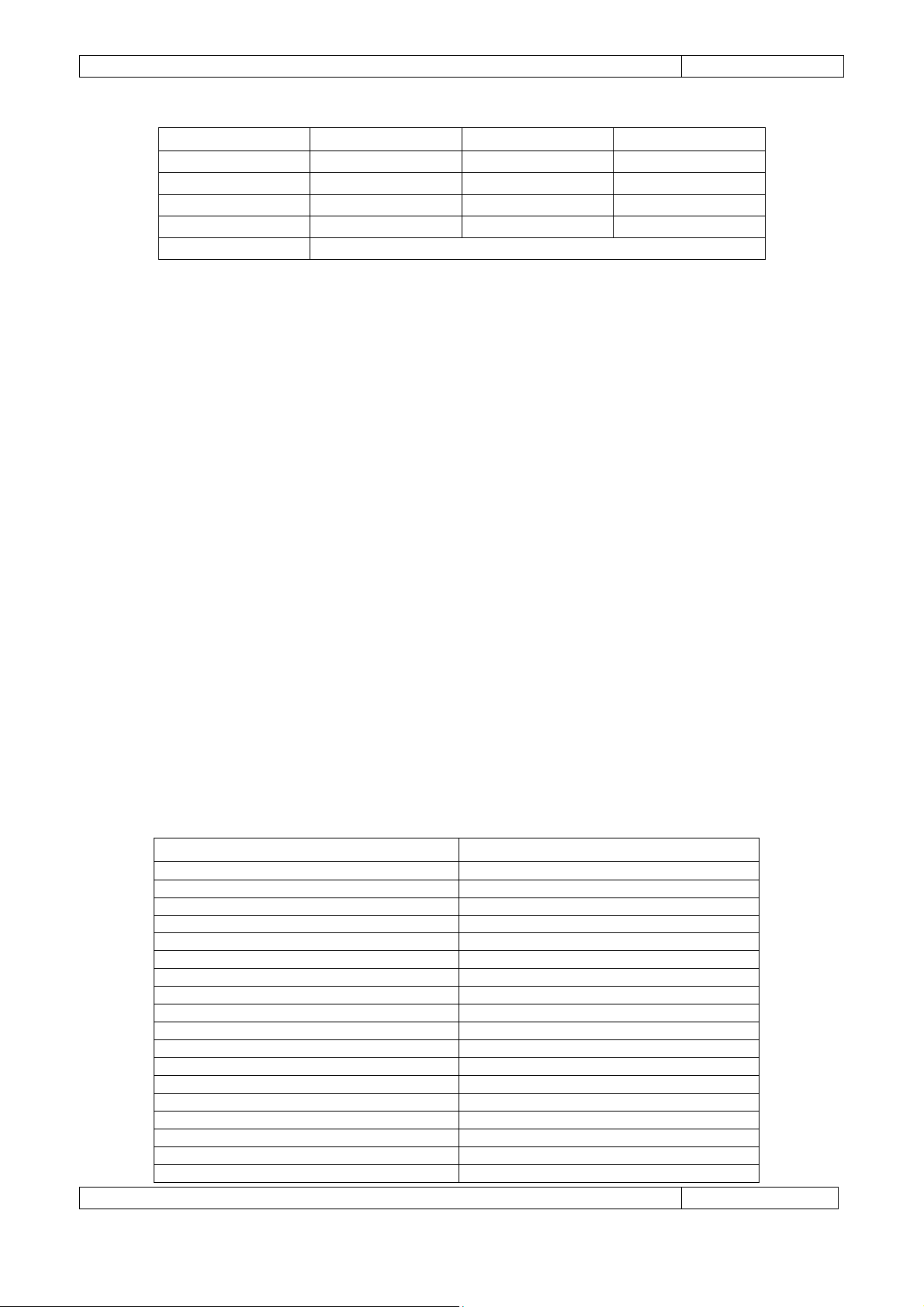
LV25-KIT-50 LV25-KIT-100 LV25-KIT-150 LV25-KIT-200
Page 13
Gimatic
- LV Electric Linear Actuators
www.gimatic.com
Page
9
Linear actuator
LV40100
LV40150
LV40200
Length [mm]
270 320 370
Total mass [g]
250 290 330
Stroke [mm]
100 150 200
Stiffness [N/m]
1225
(in preparation)
LV40-KIT-100 LV40-KIT-150 LV40-KIT-200
4.2.5 Brake
An external brake should be considered for all applications to prevent damage to systems or users in the
event of a failure or fault. A brake is recommended for vertical applications regardless of whether a counter
balance is used or not. In applications that are deemed to require brakes, it is recommended that they be
applied to the bearing or aligning rod systems used with the linear motor. A braking system should not be
directly applied to the motor's slider as this could result in damaging the slider. The brake must be chosen
so that it provides enough force to resist gravity, inertia and machine operation. The kinetic energy of the
moving load will be converted into heat due to friction when the brake is applied. The amount of kinetic
energy must be taken into account to prevent damage to the brake due to overheating.
4.2.6 Cable carrier
When the LV motor's stator is the component moving relative to the servo drive, it is recommended that a
cable carrier be used to guide and protect cables connected to the stator. Where the machine has a very
short stroke, a cable carrier may not be required. In all cases, strain relief is recommended. Refer to the
cable supplier’s information to ensure the cable bends and flexes within specification.
4.3 Servo drive
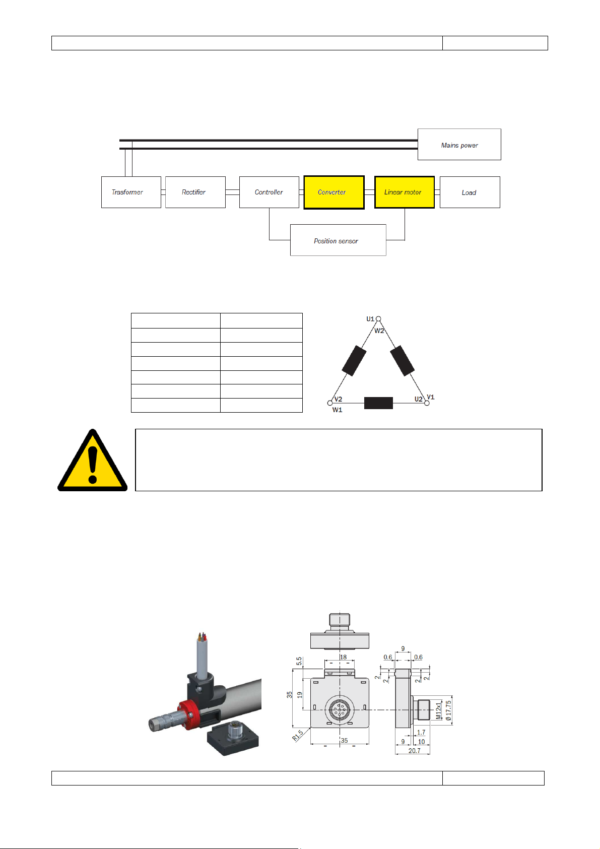
Gimatic does not manufacture servo drives since the LV actuators are compatible with most 3-phase, AC,
brushless servo drives available on the market. The following is a list of some of the commercial drives
tested over time.
BRAND CODE
Linmot B1100; E1100
Copley Accelnet
Hitachi Servo AD
Advanced Motion Control DPRALTE-020B080
Technosoft IDM680
Janaer Ecovario 114
BR Automation Apocos
Elmo Harmonica Drive
Servotronix LVD drive
Maxon Motor Epos Drive 70/10
LeadShine ACS806
Aerotech Ensemble HPE10
ABB MicroFlex 150
Galil CDS-3310
Infranor XtraPlusPac
HDT Digifox/Tomcat
Stober SD6A02TNX
Selema Micro ECO
Page 14
Gimatic
- LV Electric Linear Actuators
www.gimatic.com
Page
10
U-PHASE
Grey
V-PHASE
Yellow
W-PHASE
Brown
PTC White
PTC Pink
GROUND
Green
WARNING
: During functional tests and electromagnetic compatibility tests of
Appropriate servo drive model selection for the application and selected stator model is important for
optimum performance. Considerations include maximum current rating, continuous current rating and DC
bus voltage. These factors, in turn, influence the peak force, force duty cycle and maximum velocity of the
motor.
Please, refer to the following schema and to the specific servo-drive user manual for all the
recommendations and installation notes on connecting the motor to the driver.
Connection Color
Gimatic's LV products, shield conductors have been left unconnected from motors and
drivers.
4.4 Linear encoder
The linear encoder is used to provide position feedback to the servo drive to allow for accurate control of
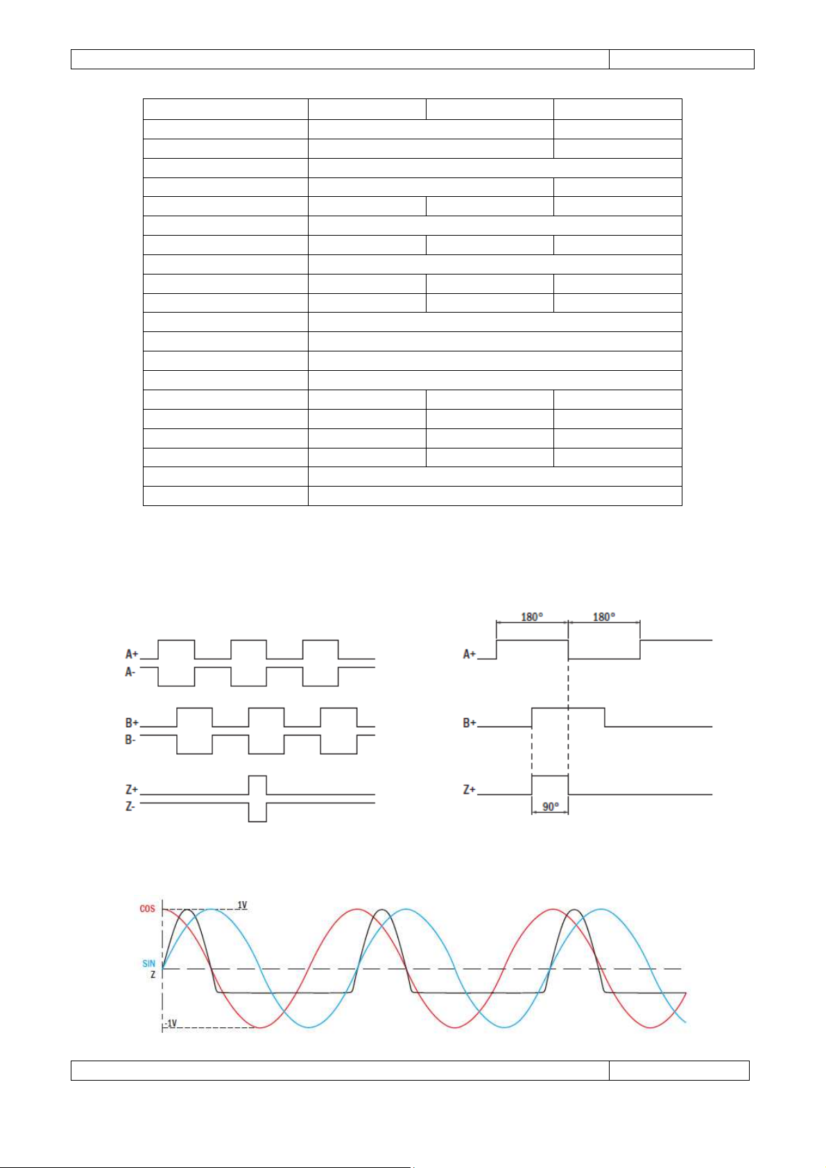
the LV actuators. Gimatic manufactures an incremental ABZ encoder with RS-422 output signal for two
different resolutions: 25 μm (SE9ABZ1) and 10 μm (SE9ABZ1-HR). The choice of what encoder best fits the
application also depends on the maximum speed expected: the higher the resolution, the lower the
maximum speed. A sine/cosine analog output version of the linear transducer is under development.
Page 15
Gimatic
- LV Electric Linear Actuators
www.gimatic.com
Page
11
Circuit out
put ABZ SIN/COS
Output signal
RS-
422 1 Vss
Power supply
5 Vdc
Current consumption
50 mA
25 mA
Working speed
6 m/s
2 m/s
4 m/s
Operating temperature
-40 ÷ +85 °C
Resolution
25 μm
10 μm
-
Pole pitch
35.4 mm
Cycles per rev. (CPR)
354 885 1
Pulses per rev (PPR)
1416
3540
1 sinusoid
Weight
20 g
Connection
M12, 8 poles
Pin 1 (White)
Z-
Pin 2 (Brown)
+5 Vdc
Pin 3 (Green)
B- B-
COS
-
Pin 4 (Yellow)
B+ B+
COS +
Pin 5 (Grey)
A- A-
SIN -
Pin 6 (Pink)
A+ A+
SIN +
Pin 7 (Blue)
GND
Pin 8 (Red)
Z+
SE9ABZ1 SE9ABZ1-HR SE9SIN1(*)
(*) Under development
Feedback signals
SE9ABZ1/SE9ABZ1-
HR
SE9SIN1
Page 16
Gimatic
- LV Electric Linear Actuators
www.gimatic.com
Page
12
NOTE
: Despite all linear encoders can be mechanically in
stalled in any of the two
WARNING
: Due to the highly magnetic nature of the slider, care must be taken when
encoder components are a sufficient distance away from the slider.
However, the user can install third party, external, position transducers whose type depends greatly on the
application. Factors such as the required precision, operating environment and servo drive signaling
requirements need to be taken into account. As the LV embedded motor does not have any backlash, it is
recommended that the position feedback system chosen does not contain backlash either. The most
commonly used encoders consist of an encoded surface, either solid rail or adhesive strip, mounted parallel
to the slider and a sensor read head mounted to the stator. LV linear actuators have been designed to be
compatible with several major brands of external transducers (i.e. Givi Misure®, Siko® and Renishaw®) by
means of specific fixing accessories (i.e. LV25-KIT-05 refer also to the "Accessories" section).
motor's grooves, the positive direction of the position measurement is opposite from
one installation side to the other.
LV25-KIT-05
LV25 LV40
installing a magnetic encoder. It is possible that the slider will affect the strip or read
head resulting in inaccuracies or damage. Therefore, it is necessary to ensure the
4.5 Sensors
Hall sensors
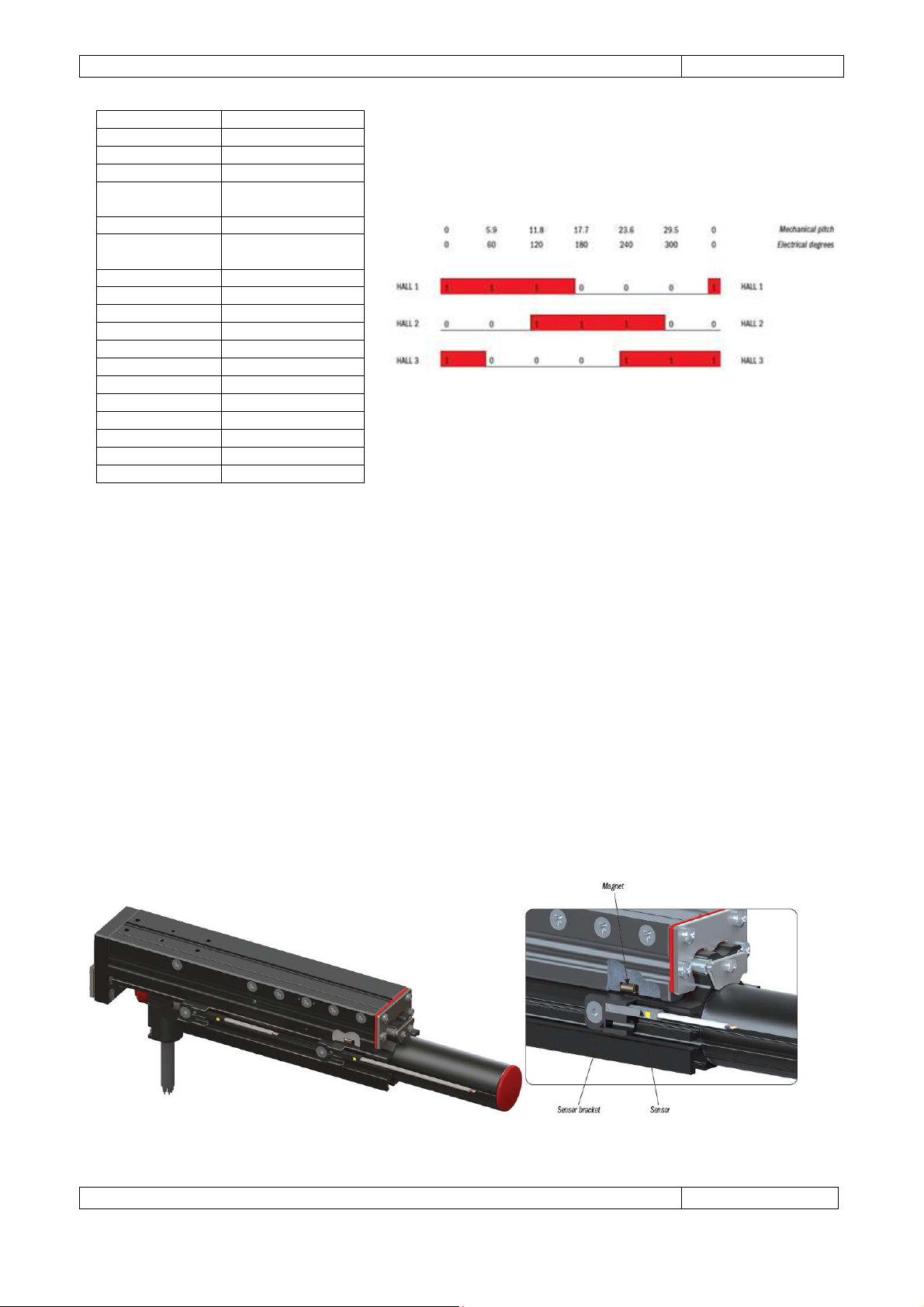
In the same package of the incremental encoder transducer, Gimatic manufactures a sensor with simulated
HALL sensors output. This accessory is especially suited for vertical applications where initial movement
usually required for the wake and shake procedure is not allowed.
Page 17
Gimatic
- LV Electric Linear Actuators
www.gimatic.com
Page
13
SE9HALL1
Circuit output 3 HALL
Output signal Open Collector
Power supply 5 Vdc
Current
consumption
Working speed 6 m/s
Operating
temperature
Resolution 60°
Pole pitch 35.4 mm
Weight 20 g
Connection M12, 8 poles
Pin 1 (White) N/C
Pin 2 (Brown) +5 Vdc
Pin 3 (Green) N/C
Pin 4 (Yellow) HALL 3
Pin 5 (Grey) N/C
Pin 6 (Pink) HALL 1
Pin 7 (Blue) GND
Pin 8 (Red) HALL 2
-40 ÷ +85 °C
25 mA
End stop Sensors
End stop sensors, also known as limit switches, are used to prevent motor travel in the case of incorrect
behavior. In the event that the motor passes a defined maximum physical position, the end stop sensors
will be triggered which can stop and/or disable the motor, minimizing potential damage. In addition to end
stop sensors, it is recommended to incorporate end stop bumpers to absorb and stop the movement in the
case of over travel. Gimatic can provide both end stop sensors and bumpers, please contact your local area
Gimatic's distributor.
Home Sensor
When an incremental encoder is used, the servo drive will not know the absolute position of the motor
relative to the machine. To establish the absolute position, it is necessary to move the motor to a known
‘home’ location, often referred to as ‘homing’. The servo drive can be informed that it has reached the
‘home’ location in many ways, the most common being via a proximity switch at one end of travel and/or
an index (marker) pulse. Frequently a home sensor is of the same type of end stop sensor. Please contact
your local area Gimatic's distributor.
Page 18
Gimatic
- LV Electric Linear Actuators
www.gimatic.com
Page
14
WARNING
: When embedded temperature
sensor (PTC) is employed a temperature
LV linear actuators are provided with special brackets allowing the usage of magnetic proximity switches as
end stop and home sensors. Since sliders of LV40 actuators show a much stronger magnetic field respect to
LV25 models, inductive proximity switches can also be used for LV40 actuators only that can be mounted
using optional brackets. Please refer to the accessories section for models and ordering codes.
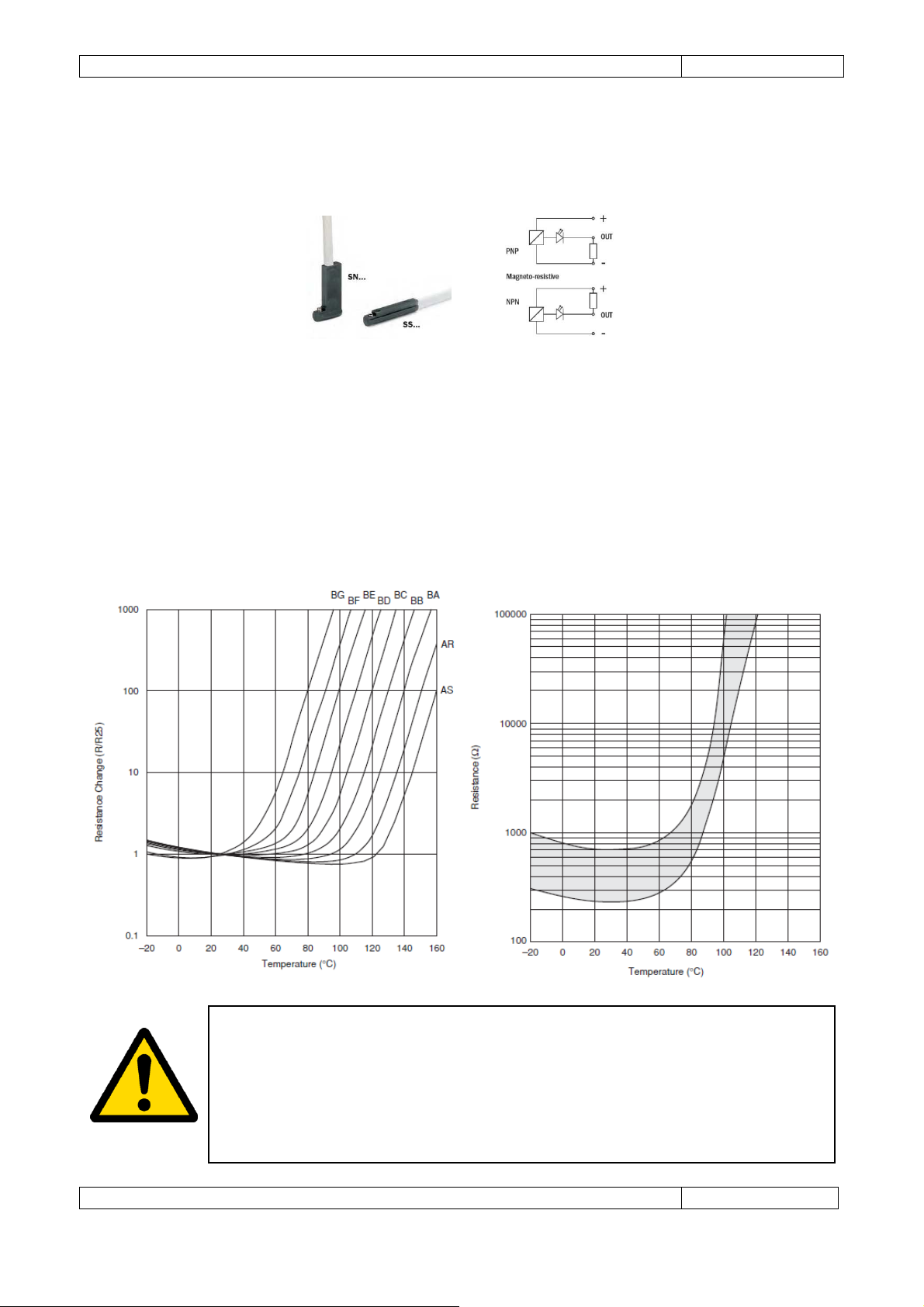
Temperature Sensor
The ML motor is fitted with a logarithmic type PTC temperature sensor. At an ambient temperature
of 25 °C, the built-in PTC sensor shows a nominal r esistance value of 470Ω. The higher the motor
temperature, the higher the sensor resistance. This kind of PTC has resistance-temperature
characteristics that cause resistance to sharply increase when the temperature exceeds the Curie
Point. The Curie Point (C.P.) is defined as the temperature at which the resistance value is twice
the one at 25°C. When this temperature sensor is employed, the trip temperature should be set no
higher than 95 °C. The graphs below show the resistance curve as a function of temperature (see
the curve BD).
value of 95 °C must be set as maximum temperature allowed for the stator during
driver’s programming. This is equivalent to the PTC value less or equal to 1330 Ω.
Whenever PTC connection is not possible a proper i2t parameter has to be set by the
user during driver’s programming in order to preserve ML stator from permanent
damaging.
Page 19
Gimatic
- LV Electric Linear Actuators
www.gimatic.com
Page
15
Operating Environment
The temperature of the operating environment is critical when determining the appropriate motor model
to use. When the motor is producing force, it will produce a temperature rise above ambient. The higher
the temperature of the motor operating environment, the hotter the motor will become under the same
duty cycle. The motor will also be subject to a temperature related reduction in the force produced.
Therefore, it is important that the motor cooling method be carefully considered. If air-cooling is used,
ensure that the motor is well ventilated to limit localized heating. If the motor is liquid cooled, ensure that
the coolant and flow rates are sufficient to maintain the motor temperature within operating limits.
It is recommended that the inbuilt temperature sensor (PTC) be monitored to prevent the motor exceeding
absolute temperature limits.
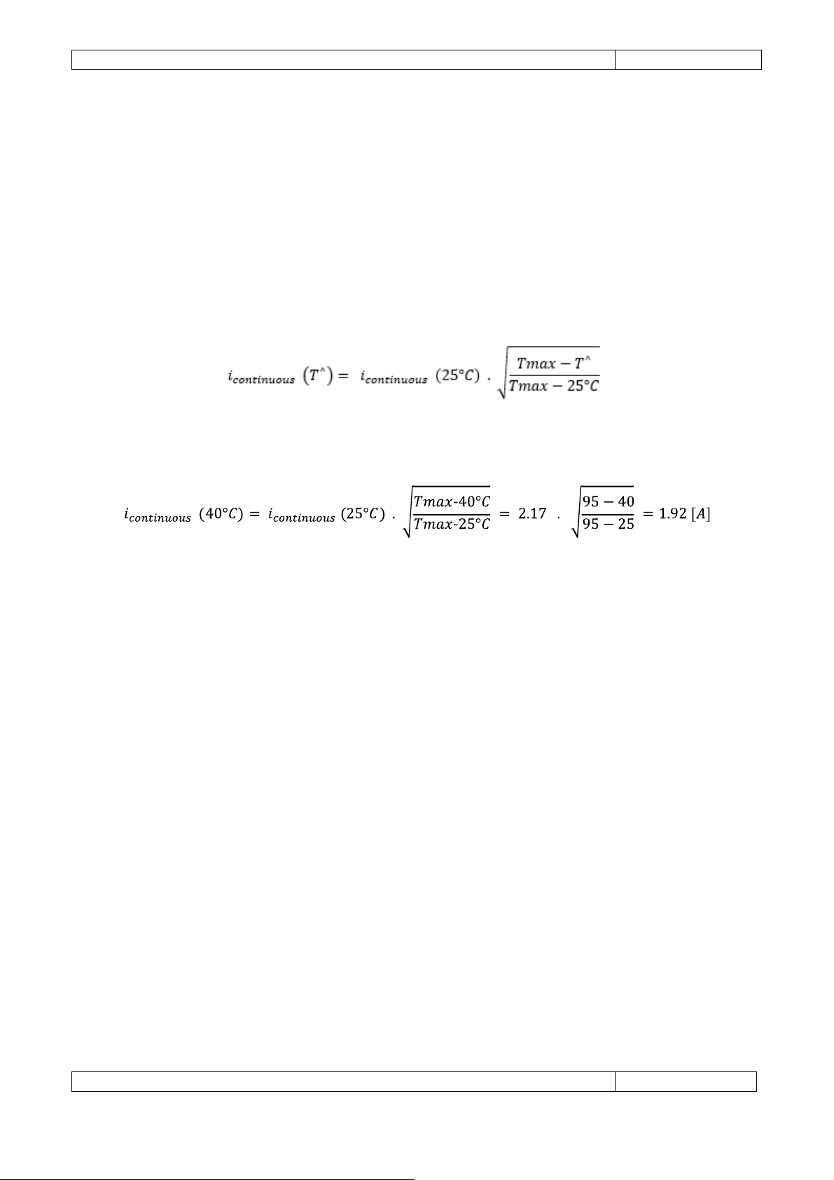
The maximum continuous current calculation in reference to environment temperature is as follows.
The following example demonstrates the calculation of the ML4070X6 continuous current in reference to
40°C environment temperature.
Page 20

Gimatic
- LV Electric Linear Actuators
www.gimatic.com
Page
16
LV25050
-70
LV25100
-70
LV25150
-70
LV25200
-70
Stroke [mm]
50
100 150 200
Mass of
parts fixed to
Total mass [g]
1170
1380
1825
2185
BUS peak voltage [Vdc]
72
Max Continuous Force [N]
20 30
Max Contin
uous Current [A]
1.57 1.48
Peak Force [N]
100 110
Peak Current [A]
7.87 5.42
Force constant [N/Arm
s] 12.7 20.3
Back EMF constant [Vs/m]
11.6 18.2
Resistance [
Ω] @25 [°C]
5
7.1
Inductance [mH]
1.2 1.9
Thermal resistance [°C/W]
3 2
Thermal constant [s]
960 1200
*) 15 65
LV25050
-
300 LV25100
-
300 LV25150
-
300 LV25200
-
300
Stroke [mm]
50
100 150 200
Mass of parts fixed to
Total mass [g]
1170
1380
1825
2185
BUS peak voltage [Vdc]
325
Max Continuous Force [N]
17 30
Max Conti
nuous Current [A]
0.49 0.48
Peak Force [N]
120 130
Peak Current [A]
3.49 2.07
Force constant [N/Arms]
34.4 62.7
Back EMF constant
[Vs/m]
36.3 57.7
Resistance [
Ω] @25 [°C]
51.2 75
Thermal resistance [°C/W]
3 2
Thermal constant [s]
960 1200
*) 15 40
5 SPECIFICATIONS
5.1 Electrical
the slider [g]
i2t [s] (
560 670 850 1050
the slider [g]
560 670 850 1050
Inductance [mH] 11.2 20.5
i2t [s] (
(*) The time for which the motor can absorb twice the nominal current without damaging it.
Page 21

Gimatic
- LV Electric Linear Actuators
www.gimatic.com
Page
17
LV40
050-70 LV40100-70 LV40150-70 LV40200-70
Stroke [mm]
50
100 150 200
Mass of parts fixed to
Total mass [g]
2730
3590
4430
4865
BUS peak voltage [Vdc]
72
Max Continuous Force [N]
42 70
Max Cont
inuous Current [A]
3.09 3.38
Peak For
ce [N]
270 320
Peak Current [A]
19.85 15.46
Force constant [N/Arms]
13.6 20.7
Back EMF constant [Vs/m]
12
17.5
Resistance [
Ω] @25 [°C]
1.9 2.6
Inductance [mH]
0.7 1.1
Thermal resistance [°C/W]
2 1.3
Thermal constant [s]
1200
1500
*) 25 20
LV40050
-
300 LV40100
-
300 LV40150
-
300 LV40200
-
300
Stroke [mm]
50
100 150 200
Mass of parts fixed to
Total mass [g]
2730
3590
4430
4865
BUS peak voltage [Vdc]
325
Max Continuous Force [N]
45 70
Max Contin
uous Current [A]
0.94 0.98
Peak Force [N]
420 440
Peak Current [A]
8.79 6.19
Force constant [N/Arms]
47.8 71.1
Back EMF c
onstant [Vs/m]
41 62
Resistance [
Ω] @25 [°C]
18.8 29
Inductance [mH]
9.1 13.3
Thermal resistance [°C/W]
2 1.3
Thermal constant [s]
1200
1500
*) 45 35
the slider [g]
i2t [s] (
1350 1840 2150 2420
the slider [g]
1350 1840 2150 2420
i2t [s] (
(*) The time for which the motor can absorb twice the nominal current without damaging it.
Page 22
Gimatic
- LV Electric Linear Actuators
www.gimatic.com
Page
18
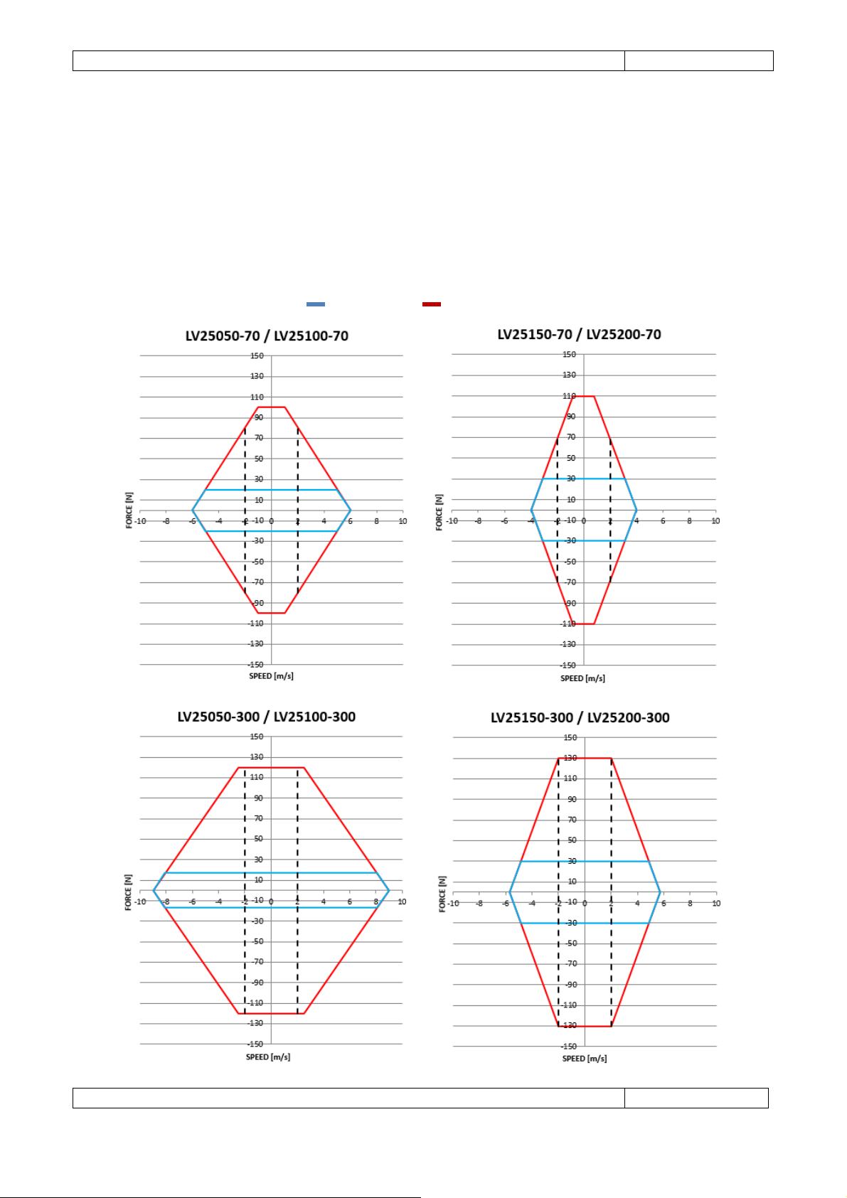
Continuous
Intermittent
5.2 Operative fields
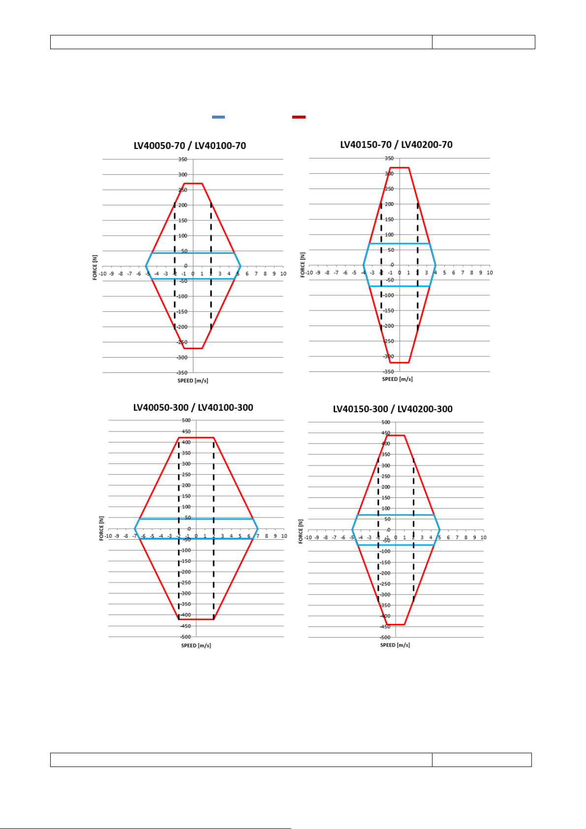
The following graphs show the operative field of LV linear actuators, that is all the possible operation points
of the actuator only. The internal portion defines the motor’s continuous operation area and shows the
conditions that enable the actuator to operate for an indefinite period of time. The remaining portion
shows the conditions that enable the actuator to operate for short periods of time only. According to the
general sizing criteria, the load’s characteristic curve should be entirely included in the intermittent area
and the operation point (rms point) should be inside the continuous area. For 10 million cycles
maintenance-free operations the maximum speed value of 2 m/s should not be exceeded.
Page 23
Gimatic
- LV Electric Linear Actuators
www.gimatic.com
Page
19
Continuous
Intermittent
Page 24
Gimatic
- LV Electric Linear Actuators
www.gimatic.com
Page
20
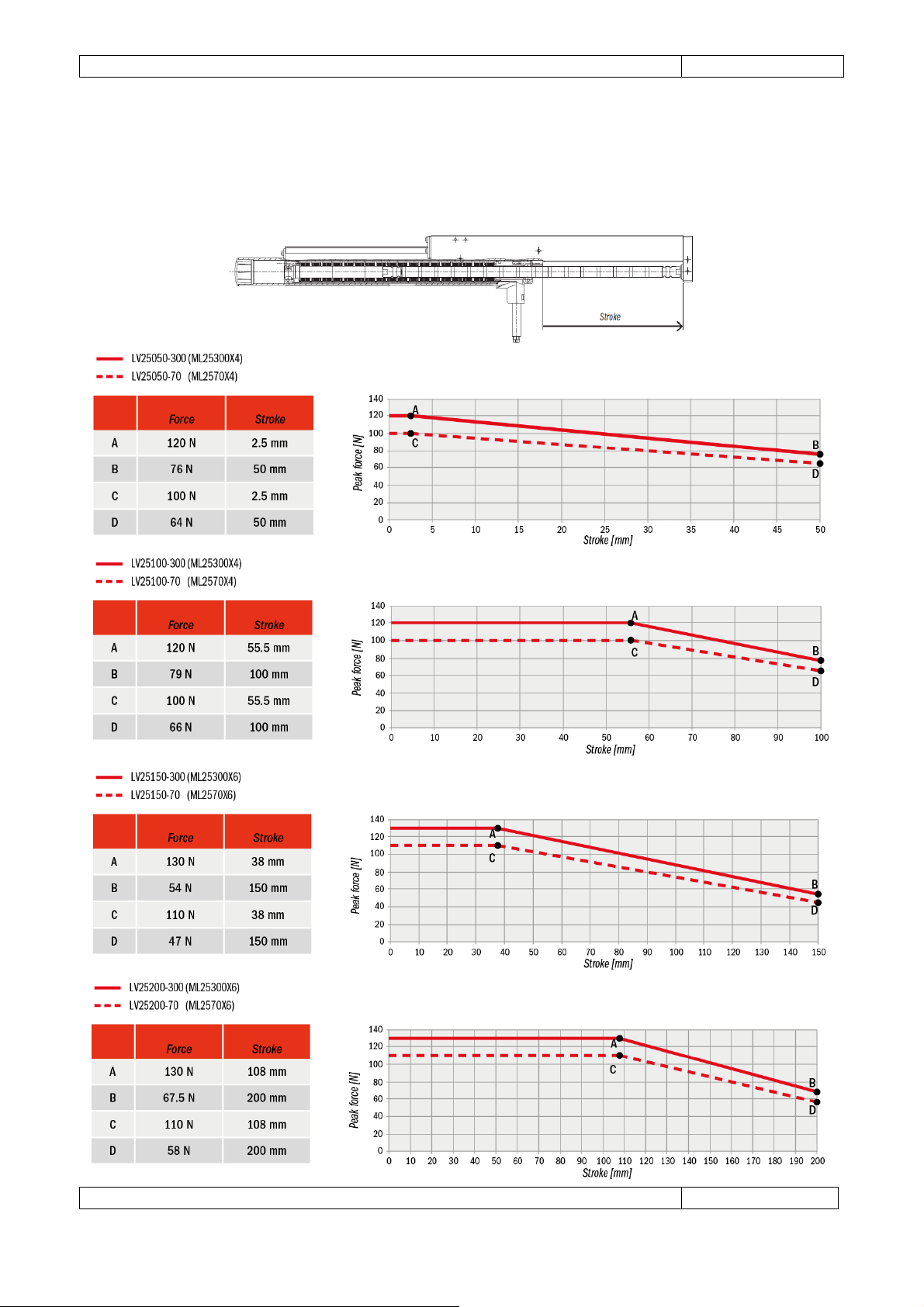
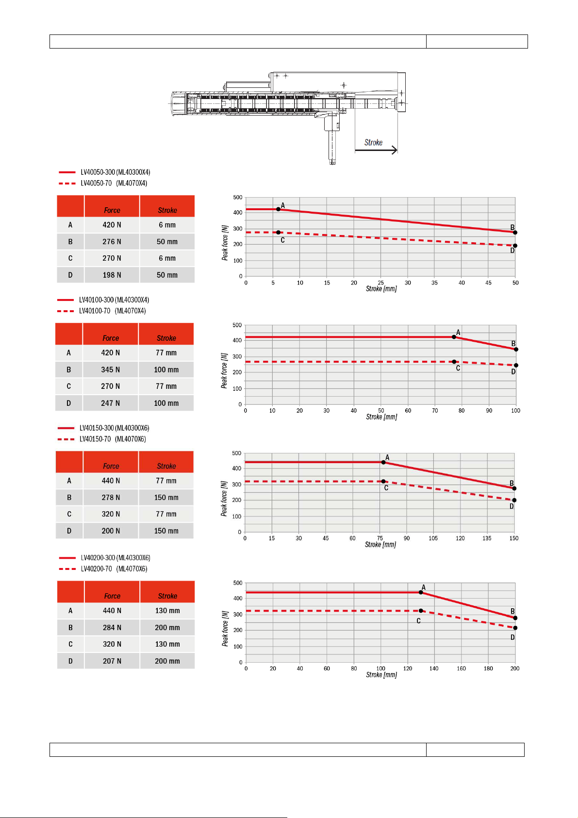
5.3 Static thrusts
The maximum thrust the linear actuator can exert depends on the slider portion inserted in the motor. The
following graphs show the variation of the maximum force that can be exerted by the motor under static
conditions.
Page 25
Gimatic
- LV Electric Linear Actuators
www.gimatic.com
Page
21
Page 26
Gimatic
- LV Electric Linear Actuators
www.gimatic.com
Page
22
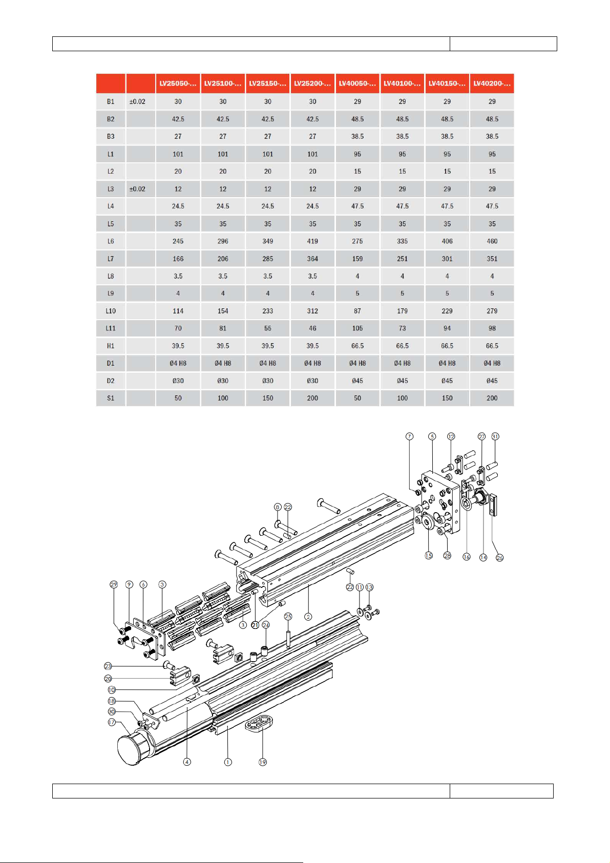
5.4 Mechanical
Page 27
Gimatic
- LV Electric Linear Actuators
www.gimatic.com
Page
23
Page 28
Gimatic
- LV Electric Linear Actuators
www.gimatic.com
Page
24
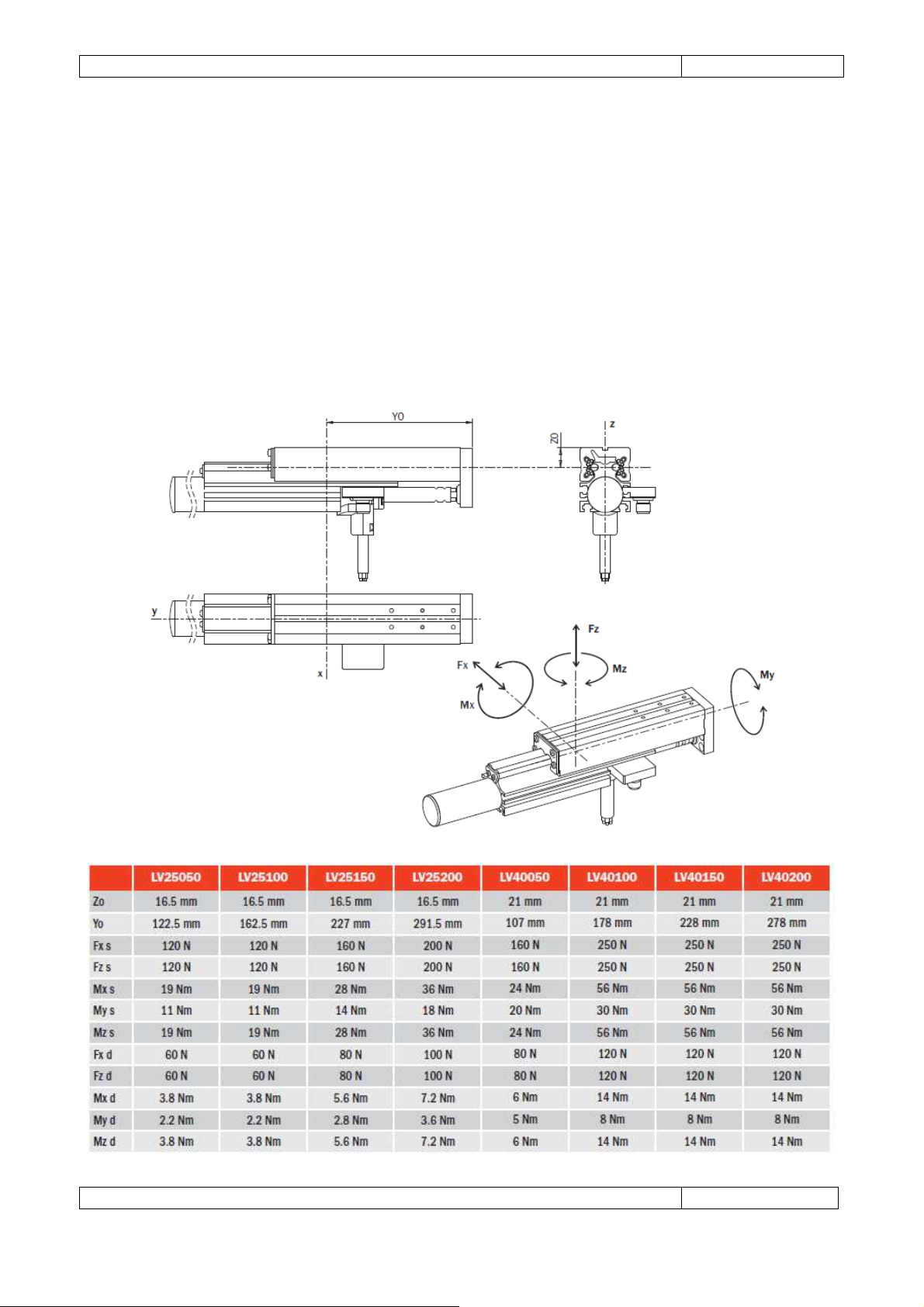
5.5 Safety loads
Excessive loads can damage the linear unit and cause functioning troubles. The dimensions Y0 and Z0
identify the centre of the linear bearing (dimensions measured under conditions of maximum
opening).
Fx s, Fz s, Mx s, My s, Mz s are maximum permitted static loads.
Fx d, Fz d, Mx d, My d, Mz d are maximum permitted dynamic loads.
The static loads can be applied when the carrier is motionless, the dynamic loads when the carrier is
running. The dynamic load represents the limit load at which actuators are tested with 1 million full
opening and closing cycles.
Page 29
Gimatic
- LV Electric Linear Actuators
www.gimatic.com
Page
25
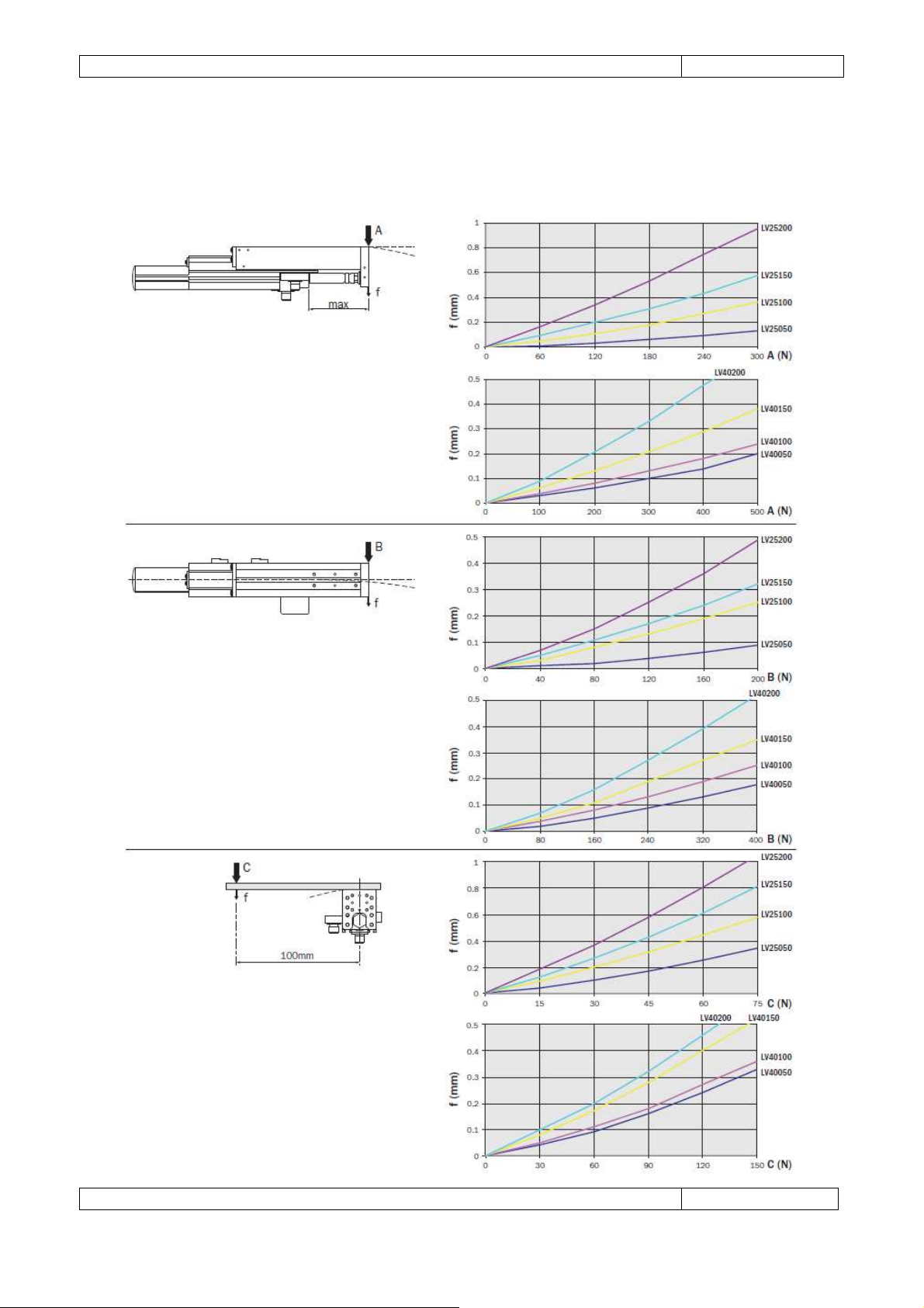
5.6 Deflection
The graphs show the deflection f (mm) in the three directions shown, as a function of forces A, B or C and
the stroke of the slide.
Page 30
Gimatic
- LV Electric Linear Actuators
www.gimatic.com
Page
26
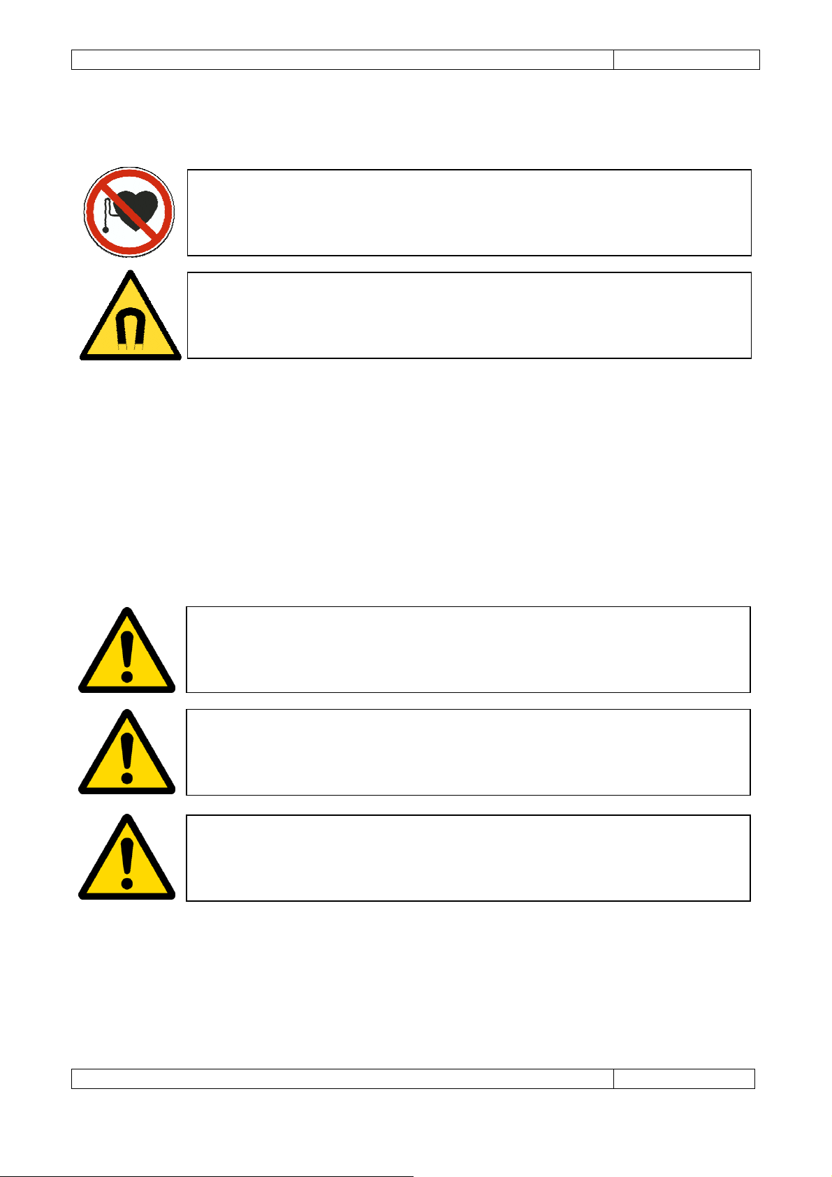
WARNING
: Tubular motor shafts contain powerful permanent magnets. People with a
WARNING
: The shaft emits a very strong magnetic field. Always use caution when
WARNING
: Surface temperatures of up to 80°C can be present during operation of the
WARNING
: Always isolate the motor from the electrical supply. The motor could move
WARNING
: The shaft emits a very strong magnetic field. Always use caution when
6 INSTALLATION
6.1 Unpacking
pacemaker, AICD or similar medical devices should maintain a minimum distance of 30
cm from the shaft
handling. To avoid injury, keep fingers and other body parts clear.
Before unpacking commences, wait for the actuator to reach room temperature to prevent condensation.
Once at room temperature, remove protective packaging from the device. Due to the magnetic nature of
the slider, it is recommended that protective material around the slider be left on as long as possible during
installation. During installation, ensure that the actuator is kept on a clean surface away from any other
magnetic and ferrous materials.
If the slider is to be left unattended, precautions should be taken to prevent accidents or damage due to its
strong magnetic field. All personnel involved in transporting, storing, installing and/or maintenance of the
actuator must be made aware of the potential hazards involved.
6.2 Mechanical
LV system. Allow the actuator to cool before touching the LV.
unexpectedly and present a crushing hazard.
handling. To avoid injury, keep fingers and other parts clear.
Due to the strong magnetic nature of the slider, proximity to magnetic parts and items sensitive to
magnetic fields must be considered at all times. It is recommended that nonmagnetic packing material be
used when adjusting the actuator to prevent the slider being attracted to any magnetic parts e.g.
ferromagnetic brackets.
Page 31
Gimatic
- LV Electric Linear Actuators
www.gimatic.com
Page
27
LV25
LV40
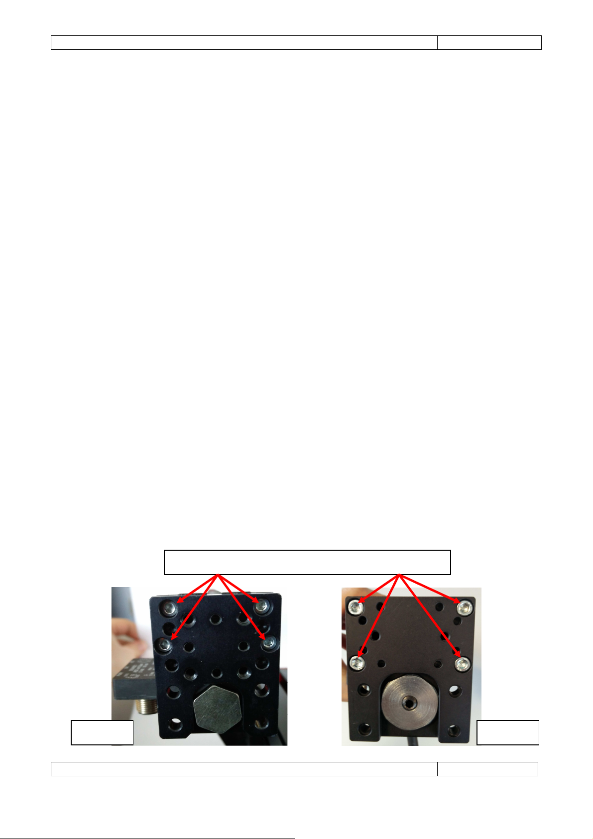
Remove these screw to extract the slider from the carriage
6.2.1 Linear encoder
Third party encoders should be installed according to the encoder manufacturer’s instructions. Care should
be taken with the sensitive electronics of the encoder near the strong magnetic field of the slider. Particular
care should be taken with magnetic encoders as close proximity to the slider could cause inaccuracies or
damage. Installing the encoder at a minimum distance of 150 mm from the slider is recommended.
The positive and negative directions of the linear encoder need to be correctly aligned to the direction of
motor movement.
The direction of the encoder can be adjusted in multiple ways:
1. mechanical orientation of the encoder;
2. electrical wiring between the encoder and servo drive (on an incremental encoder, inversion of one of
the quadrature signals is sufficient);
3. software configuration on the servo drive.
In case of first installation or replacement of Gimatic's position transducers and/or sensors (SE9 series),
please refer to the following steps:
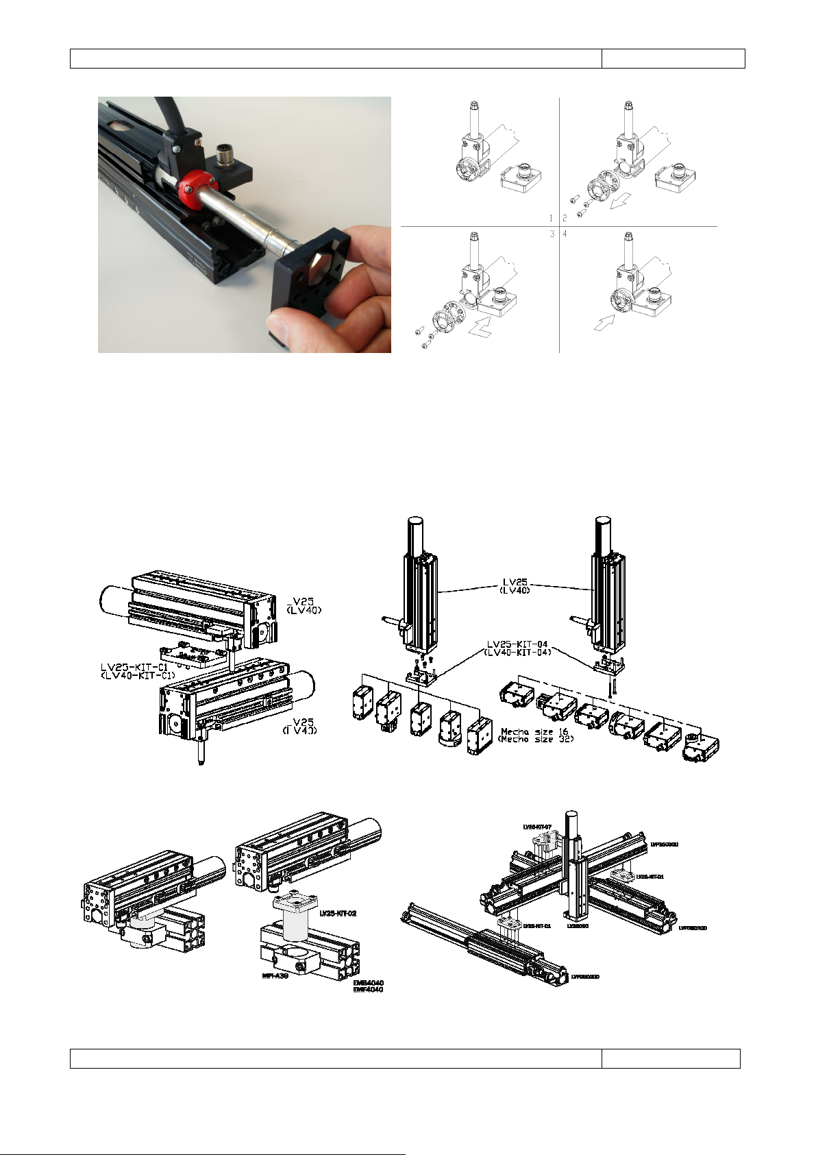
• disconnect the power supply of both the motor and the transducer to replace (if present);
• identify the cover at the cable output side of the motor (step 1 of the following schema);
• remove the 4 frontal screws and extract the slider from the carriage of LV (see following images);
• remove the fixing screws of the cover (step 2 of the following schema);
• eventually remove defective transducer (step 2 of the following schema);
• check the model of the new transducer (i.e. read the text printed on the transducer itself);
• insert the new transducer in the motor's groove (step 3 of the following schema);
• re-mount the cover and all the 3 fixing screws (step 4 of the following schema);
• re-insert the slider into the carriage of LV and fix it with the 4 frontal screws;
• reconnect and power on the transducer only;
• check the presence of the power supply (i.e. green fixed light);
• in the case a red fixed light is present two different situations may occur:
o the installed transducer is defective (in this case replace the transducer with another one or
contact your local area support);
o the transducer is not in front of the slider (be sure the slider is installed).
• move the moving part of the motor back and forth several times along the whole stroke (this
operation is necessary in order to let the transducer identify the strength of the slider's magnetic
field).
Page 32
Gimatic
- LV Electric Linear Actuators
www.gimatic.com
Page
28
6.2.2 Mounting examples
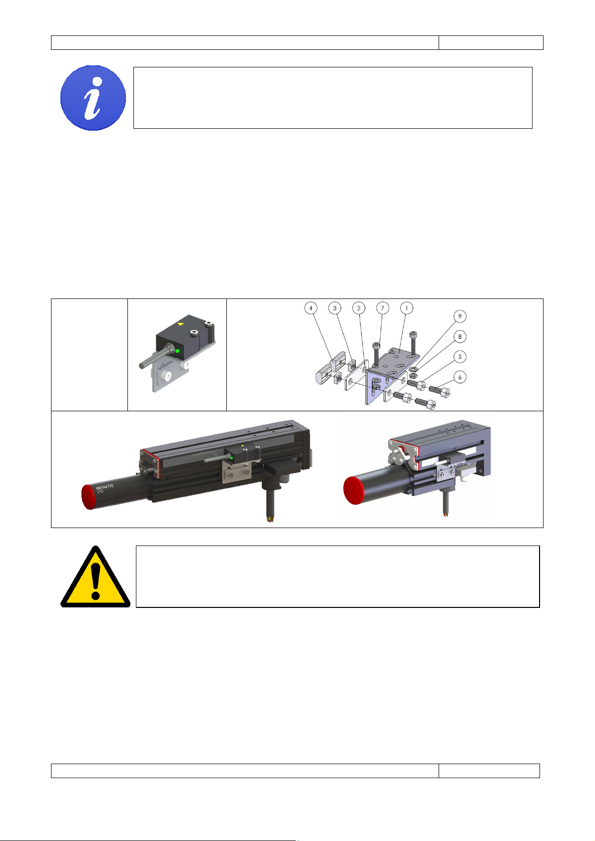
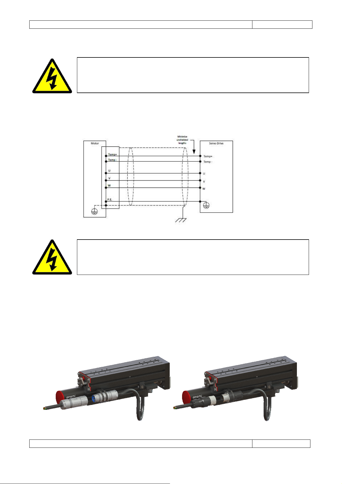
Several mounting interfaces are available to connect LV actuators with other LV units, LVP guides, gripping
and rotating devices of Gimatic's Mechatronics series. An overview on some mounting solutions is
summarized here in the following pictures but many others are possible. Please refer to the accessories
section for a complete list of available interfaces and ordering codes.
Page 33
Gimatic
- LV Electric Linear Actuators
www.gimatic.com
Page
29
DANGER HIGH VOLTAGE:
Ensure pow
er has been completely disconnected before
DANGER:
The actuator must be grounded to prevent the possibility of electric shock
6.3 Electrical
touching electrical connections. Electrical shock can cause serious or fatal injury.
6.3.1 Motor power and temperature feedback
during motor operation.
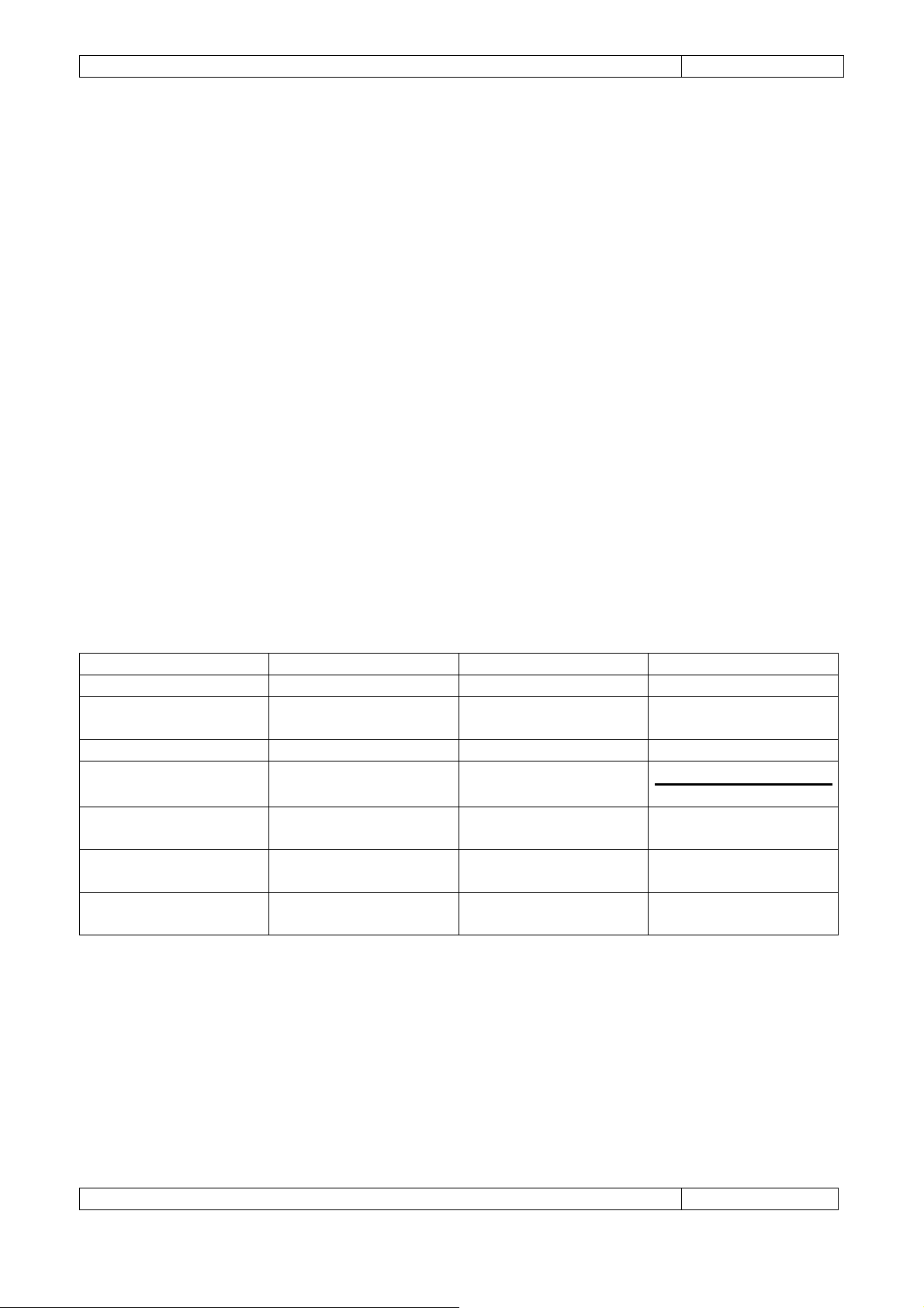
Any Gimatic’s ML motor is provided with a 30 mm log flying cable output. The power supply and
temperature signal cable can be directly connected to a servo drive by means of an extension cable and
either EN175000 7-pole circular connectors (for 70 V BUS voltage) or M23 6 pole circular connectors (for
325 V BUS voltage). Male connector should be used for the motor side while female connector should be
used for the extension cable side. The 30 mm cable must be fixed respect to the stator in order to avoid
fatal stress to the cable output while the extension cable can be used in dynamic conditions eventually in
combination with cable carriers. Please refer also to the "Accessories" section and to the servo drive
documentation for further information on how to wire in the motor power supply and temperature sensor.
Page 34
Gimatic
- LV Electric Linear Actuators
www.gimatic.com
Page
30
Parameter
Units
Linear Motor
Linear as Rotary Motor
Motor Type
-
Linear
Rotary
Distance between
Distance or encoder
As per motor
As per motor
Number of Motor Poles
Integer
- 2
Magnet Pitch
As per encoder
As per motor
As per motor
As per motor
As per motor
6.3.2 Sensors
Connect the sensors, such as home switches and dead stops, to be used to the servo drive as specified in
the sensor and servo drive documentation.
6.3.3 Electromagnetic Compatibility (EMC)
While the ultimate responsibility for a system’s EMC compliance lies with the system builder, the LV design
provides good EMC performance as a system component.
The following are general recommendations when using the LV actuator to minimize Electromagnetic
Interference (EMI) in the system.
• Keep all cable routing as short and direct as possible;
• Separate low voltage signal cables from power cables and noisy components.
• Ensure cable shielding is terminated correctly.
• Other sources of EMI in the system, such as servo drives, must also be considered for EMC, refer to
component documentation for further information.
6.4 Servo Drive Configuration
In general, servo drives will need the following configuration to control the ML motor. Servo drives that do
not specifically support linear motors can be configured as a 2-pole rotary motor. Configuration
requirements will depend on the specific servo drive and linear encoder used; refer to product
documentation for specific information.
magnet poles
Rotary encoder pulses
per revolution
Linear encoder pitch Distance
Peak Current Amps
Continuous Current Amps
Encoder counts/lines -
counts
specification
specification
specification
specification
specification
Linear Encoder Pitch
-
specification
specification
Page 35
Gimatic
- LV Electric Linear Actuators
www.gimatic.com
Page
31
7. MAINTENANCE
LV linear actuator requires very little maintenance. However, the following activities are recommended for
periodic maintenance.
• Ensure the stator can move freely over the entire stroke.
• Clean any accumulated debris from the slider.
• Check the slider deflection is within specification.
• Ensure all parts are secured.
• Check cables for signs of wear or damage.
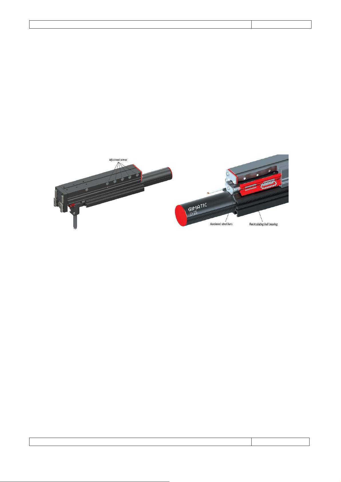
A smooth motion of LV actuators relies not only on linear motor but on recirculating ball bearings as well.
Periodically check the steel bars and lubricate when dry. Eventually adjust ball bearing preload acting on
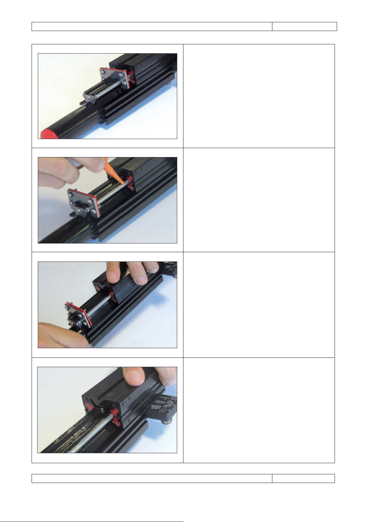
dedicated adjustment screws. Please refer to the following procedure for lubrication operation.
Page 36
Gimatic
- LV Electric Linear Actuators
www.gimatic.com
Page
32
Remove the protection metal plate.
Lubr
icate the steel bars.
Move the carrier to distribute the lubricant in the
Pay attention not to drive the carrier out of the
ball bearings.
guide.
Page 37

Gimatic
- LV Electric Linear Actuators
www.gimatic.com
Page
33
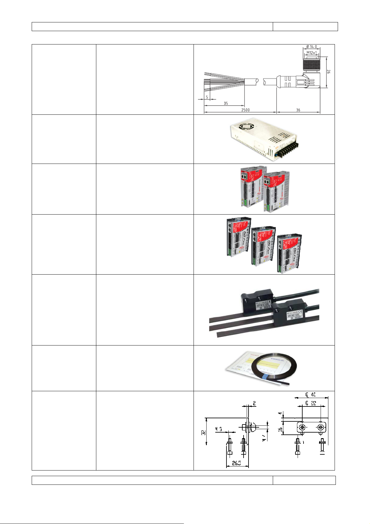
Part Number
Description
Image
8. ACCESSORIES
Cabling connector EN175000, 7
CMGM2200700
CFGM2200700
CMGM2300600
poles, male version (motor side)
Cabling connector EN175000, 7
poles, female version (extension
Cabling connector M23, 6 poles,
male version (motor side) for
for 72 Vdc BUS voltage.
Weight 55 g
cable side) for 72 Vdc
BUS voltage.
Weight 55 g
325 Vdc BUS voltage.
Weight 85 g
CFGM2300600
LV25-KIT-16
SPZ-6P-090T-02500
SPZ-6P-090T-05000
SPZ-6P-090T-10000
CFGM1200825P
Cabling connector M23, 6 poles,
female version (extension cable
side) for 325 Vdc BUS voltage.
Weight 105 g
Bracket for fixing EN175000 and
M23 connectors to LV frame.
Cable
4x 14(AWG)+2x18(AWG)
+ Drain Wire (19x0.15)
UL STYLE 20234 for ML and
dynamic applications.
Specific weight 127 g/m.
Cabling connector M12, 8 poles
straight for connection of SE
series transducers, with 2.5 m
pig tailed cable output.
Page 38
Gimatic
- LV Electric Linear Actuators
www.gimatic.com
Page
34
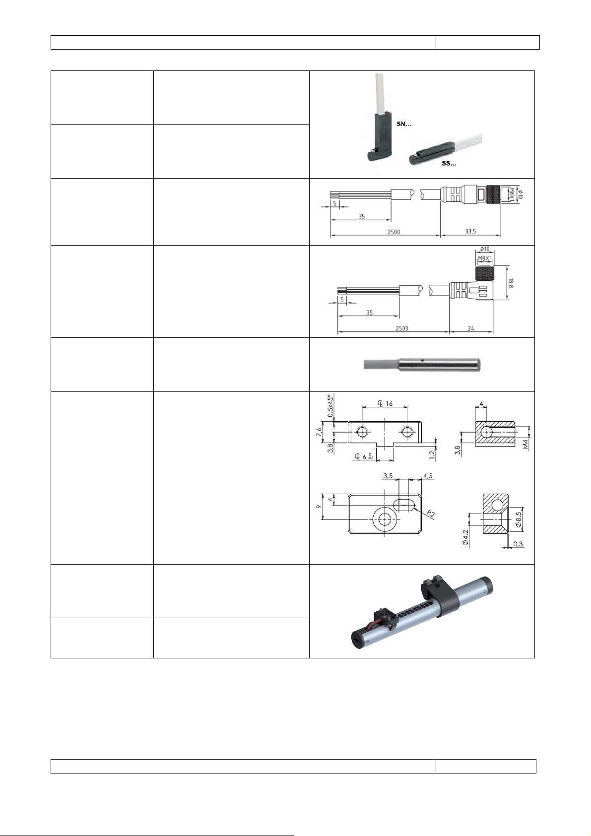
CFGM1290825P
MPS24-8.4
MPS24-13
DRV300IN040IP080
Cabling connector M12, 8 poles
90 degrees for connection of SE
series transducers, with 2.5 m
pig tailed cable output.
Power supply unit series SP with
universal AC input and 24 Vdc
output (available with 8.4 A and
13 A as nominal current) by
MeanWell®.
Driver TomCat-EVO
TMC240-EVO 4/8
(for ML25300 and ML40300)
DRV070IN100IP200
SEXT20SIN020
SEXT20BAND015
Driver DGFox-EVO 60-10-20
(for ML2570 and ML4070)
External linear position
transducer series
MTV M2KC 528VS M02/N SC by
Givi Misure®.
External magnetic strip 1.5 m
long for linear position
transducer series
MP200 + stainless steel cover
CV103 by Givi Misure®.
LV25-KIT-05
LV25 and LV40 mounting
interface for external
transducers.
Page 39
Gimatic
- LV Electric Linear Actuators
www.gimatic.com
Page
35
SN4N225
-G
Magnetic proximity switches (N
SN3N203
-G
Magnetic proximity switches (N
Cabling connector M8, 3 poles
Inductive proximity switches Ø4
LV25
-
KIT-50
LV40
-
KIT-100
Spring compensator for weight
SN4M225-G
SS4N225-G
SS4M225-G
SN3M203-G
SS3N203-G
SS3M203-G
CFGM800325P
CFGM890325P
SI4N225-G
SI4M225-G
for PNP and M for NPN output)
with 2.5 m pig tailed cable
output.
for PNP and M for NPN output)
with 0.3 m cable output length
and M8 connector.
straight for connection of
magnetic proximity switches,
with 2.5 m pig tailed cable
output.
Cabling connector M8, 3 poles
90 degrees for connection of
magnetic proximity switches,
with 2.5 m pig tailed cable
output.
mm (N for PNP and M for NPN
output) with 2.5 m pig tailed
cable output.
LV40-KIT-16
LV25-KIT-100
LV25-KIT-150
LV25-KIT-200
LV40-KIT-150
LV40-KIT-200
Mounting bracket for inductive
proximity switches SI series
(only for LV40).
Spring compensator for weight
counterbalance on LV25
actuators.
counterbalance on LV40
actuators.
Page 40
Gimatic
- LV Electric Linear Actuators
www.gimatic.com
Page
36
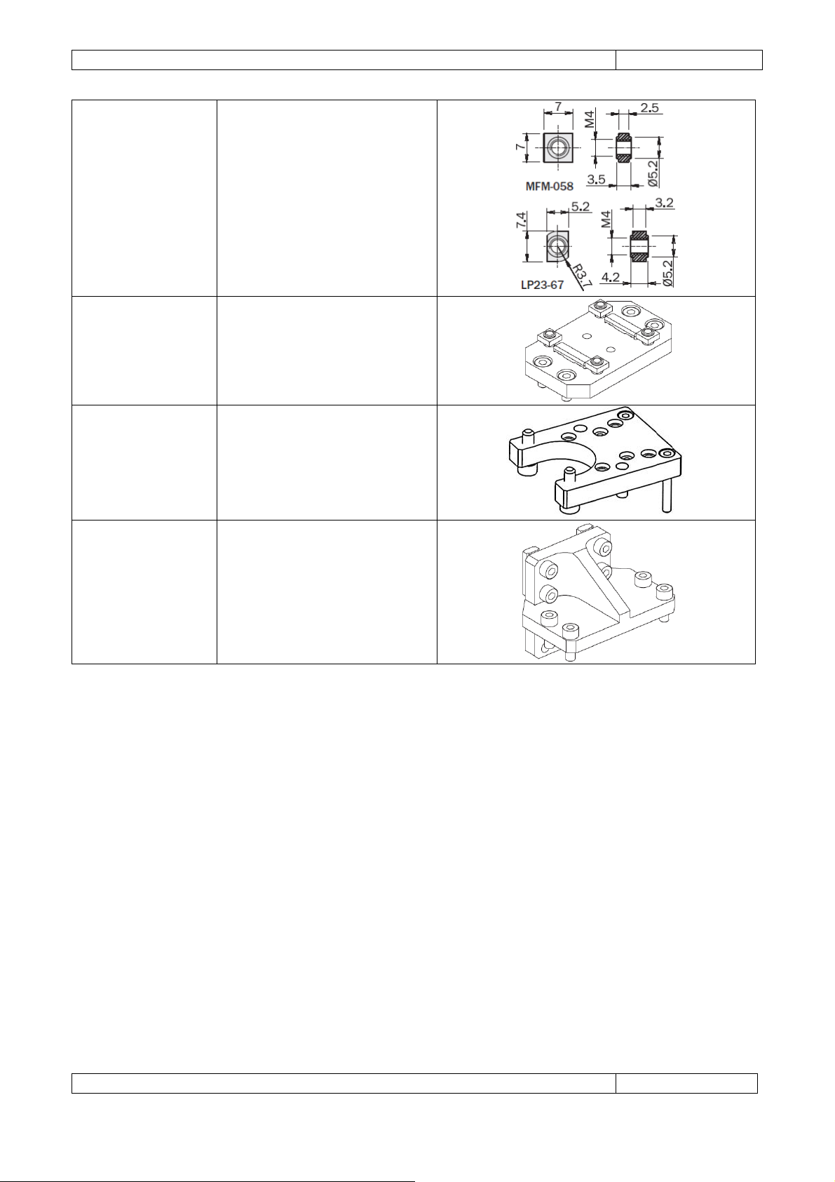
MFM-058
LP23-67
LV25-KIT-01
LV40-KIT-01*
LV25-KIT-04
LV40-KIT-04*
LV25-KIT-07
LV40-KIT-07*
T-nuts for LV slots.
LV over LV/LVP mounting
interface plate.
LV head interface.
LV over LV/LVP angular
mounting
interface plate.
(*) Under development.
For a complete and up to date list of accessories, please refer to Gimatic’s website www.gimatic.com
Page 41
Gimatic
- LV Electric Linear Actuators
www.gimatic.com
Page
37
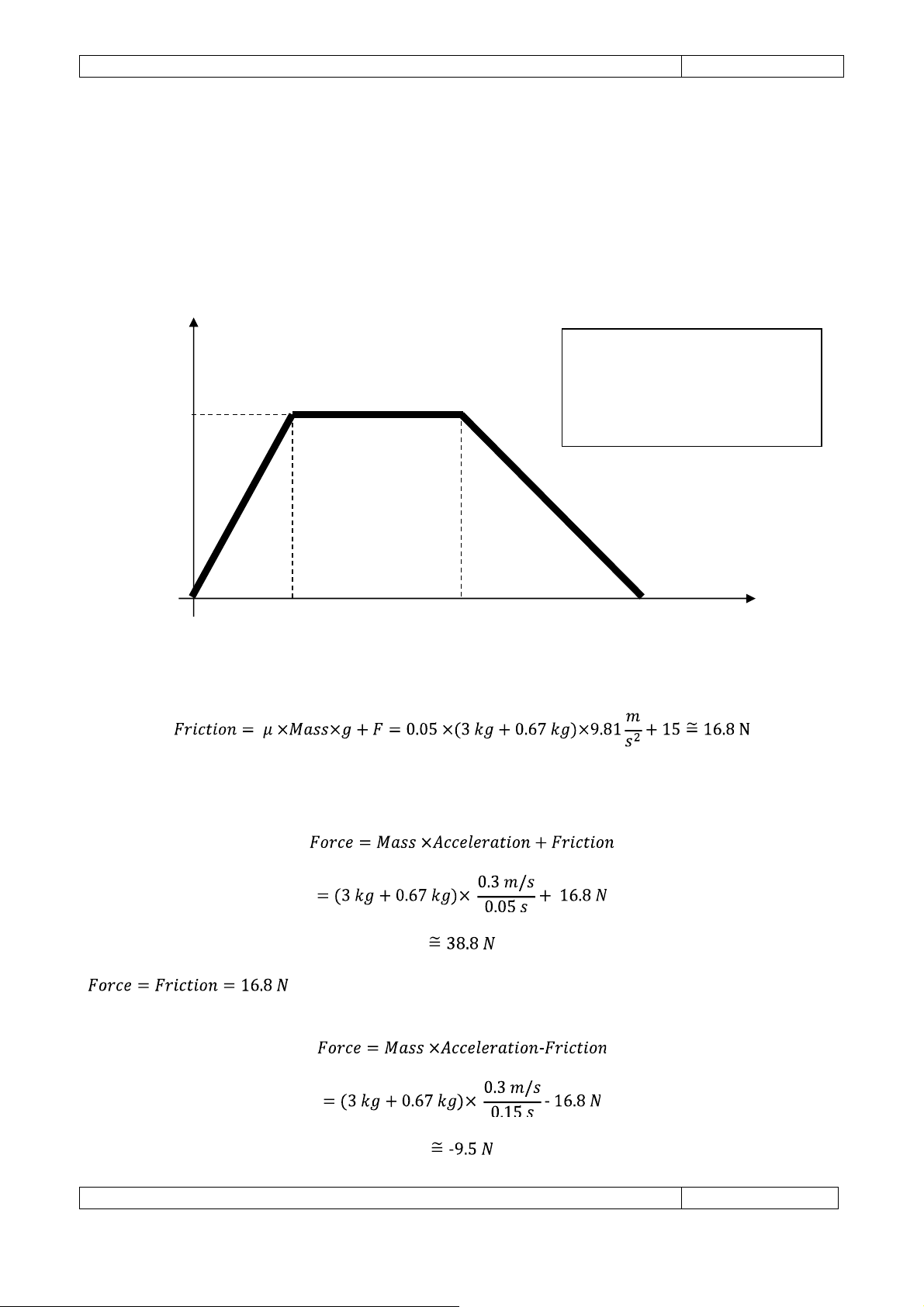
Velocity
Time
0.05 s
0.15 s
0.3 s
0.3 m/ s
Acceleration Deceleration
Constant
Load
Mass = 3 kg
Positioning example velocity profile
9. APPENDIX
9.1 Application continuous force calculation example
The following example demonstrates calculation of a LV25100-70 duty cycle for a simple horizontal
positioning movement with a trapezoidal velocity profile. The profile is broken up into sections i.e.
acceleration, constant velocity and deceleration in order to determine the RMS force and duty cycle.
velocity
In this example, friction is taken as a combination of the Coefficient of Friction (μ) and a constant force.
Carriage Mass = 0.67 kg
Coefficient of Friction (μ) = 0.05
Friction Force (F) = 15 N
Referring to the previous picture, the positioning move can be broken down into the following segments:
Acceleration
Constant Velocity
Deceleration
Page 42
Gimatic
- LV Electric Linear Actuators
www.gimatic.com
Page
38
Other application forces must also be taken into consideration such viscous and external forces; however,
for the sake of simplicity, they will be ignored in this example.
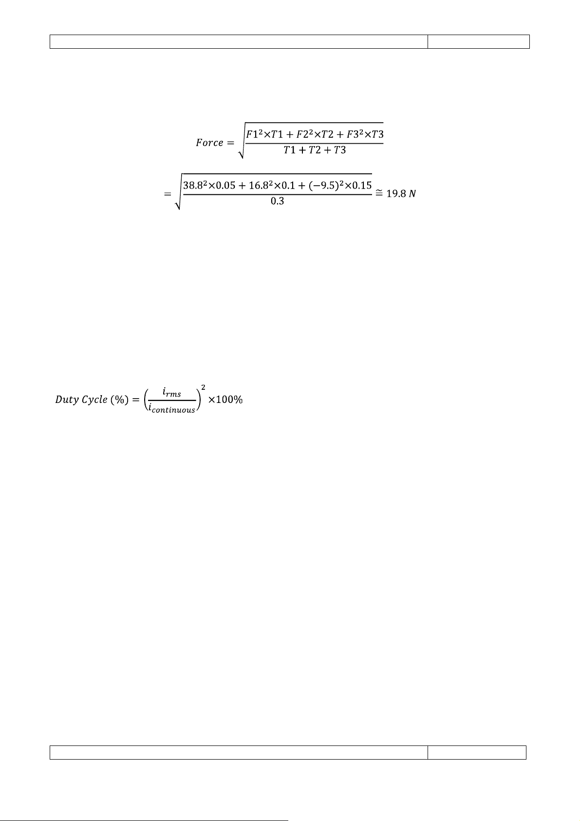
Force RMS
This motion can be cyclically actuated by Gimatic's LV25100-70 motor because the value of the calculated
force RMS is lower than the maximum continuous (19.8 N < 20 N), that the maximum force required is
lower than the motor's peak force (38.8 N << 100 N) and the maximum speed is lower than the maximum
speed suggested for the 10 milion cycles maintenance-free operation (0.3 m/s << 2 m/s).
9.2 Duty cycle calculation
The duty cycle of a linear motor is defined in terms of power usage and can be used to determine whether
the application RMS current (i
required to keep the linear motor within its specifications. Exceeding 100% duty cycle could result in
damage to the motor.
) is too high for the chosen stator. A total duty cycle less than 100% is
rms
10. SERVICE ENQUIRIES
10.1 Main application data
In order to properly size an actuator for a specific application, the following information should firstly be
collected:
• Required stroke
• Duration of the motion cycles
• Orientation of the motion (horizontal or vertical)
• Movement condition (continuous or intermittent)
• Mass of the load
• External axial force profile as a function of the working cycle
• External transversal forces
• Environment temperature
• Type of the Fixation of the stator (i.e. flange)
• Required positioning resolution
• Nominal supply voltage
• Required environmental degree of protection
Page 43

Page intentionally left blank
Page 44

GIMATIC S.R.L.
Via Enzo Ferrari 2/4 25030 Roncadelle (Bs) Italy
Tel: +39 030 2584655 Fax: +39 030 2583886
 Loading...