

Page 1

USEFUL LIFE
The useful life of the device is established in years 5 from the commissioning. For this period Titanox s.r.l.
guarantees the availability of spare parts and safe operation as long as the environmental and use conditions
defined in the instructions for use are respected by the user.
The supplier of the electronic card states that "the capacity of the memory of the mounted microprocessor is
1,000,000 cycles. By cycle we mean every ignition of the card: therefore in 10 years (3650 days) 274 daily
ignitions are allowed ... "
The manufacturer of the microprocessor does not guarantee its availability in the next 10 years: for this reason
TITANOX has decided to reduce the "useful life" to 5 years, thus having the tranquillity of being able to provide
customers with an efficient after-sales service.
INSTRUCTIONS MANUAL
DRY HEAT STERILIZING UNIT
MOD. PASTEUR ELECTRONIC
0476
2266003388 TToorrrree ddèè PPiicceennaarrddii ((CCRR)) –– IITTAALLYY –– VViiaa CCaannoovvee,, 22//AA –– CCaannoovvee ddèè BBiiaazzzzii
THESE INSTRUCTIONS HAVE ALWAYS TO FOLLOW THE UNIT.
FOR SAFETY WARNINGS PLEASE READ THE INSTRUCTIONS ON PAG. 6
TITANOX
FFAABBBBRRIICCAA AARRTTIICCOOLLII MMEEDDIICCOO SSAANNIITTAARRII
MMEEDDIICCAALL SSAANNIITTAARRYY IITTEEMM FFAACCTTOORRYY
TTeell.. ((00003399)) 00337755 339944006655 ((rr..aa..)) –– FFaaxx ((00003399)) 00337755 339944006677
s.r.l.
Rev. 16 2019-02-26
Page 2
INTENDED USE
The device is designed to be used in sanitary environments for the purpose of sterilizing non-heat
sensitive medical and surgical instruments. The process of disinfection is based exclusively on the
thermal destruction of the microorganisms present upon the instruments at a typical temperature of
about 180º C.
Effectively reaching a sterile state for the instruments inserted into the sterilizers depends upon
multiple factors:
The level of initial contamination of the instruments (total bacterial load);
The type of contaminating microorganisms;
The permeability of all the contaminated instrument parts by the hot air produced by the
sterilizer.
For more information see the paragraph **attention** ahead.
The device must be used only and exclusively by qualified personnel.
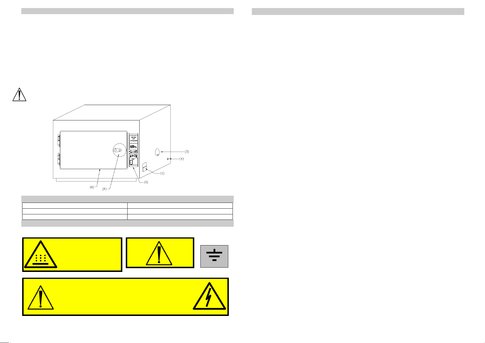
INDEX
Pos. 1 CPS Control Panel Pos. 4 Security thermostat 260° C
Pos. 2 Connection plug with fuses Pos. 5 Closure with key
Pos. 3 Air-inlets for air circulation Pos. 6 Silicone gasket
SYMBOLS AND SAFETY WARNINGS
ATTENZIONE: ALTA TEMPERATURA
ATTENTION: TEMPERATURE ELEVEE
CAUTION: HOT SURFACE
ACHTUNG: HEISS
PRECAUTION: ALTA TEMPERATURA
PROTECTION
BINDING-CLAMP
AT TENZ IONE : P R I M A D I A P R I R E T O G L I E R E LA T E N SION E
C A U T I O N : D I S C O N N E C T V O L T A G E B E F O R E O PE N I NG
AT TENT ION : A V A N T D’O U V R I R, E N L E V E R L A T E N S I O N
A C H T U NG: VO R DE M OF FNE N ST ROMV ERSO RGUN G UN TERB RECH EN
C U I D A D O : A N T E S D E A B R I R D E S C O N E C T AR LA TE NSIÓ N
C U I D A D O : A N T E S D E A B R I R T I R A R A T E N S Â O
WARRANTY CONDITIONS
1) The device is warranted for a period of one year from date of purchase.
2) Warranty covers the substitution or repairs free-of-charge of components with
manufacturing defects.
3) The device will be repaired only at our factory. Charges, risks arising from the
transport of the device shall be on purchaser’s account.
4) In the event of repairs at purchaser’s home, purchaser shall be charged fixed call costs
covering partial reimbursement of travel and professional visit by personnel.
5) Warranty coverage excludes: internal lighting, damages caused by carelessness of
purchaser, incorrect and improper uses and installations not conforming to warnings,
indicated in these booklet instructions or in any case results from phenomenon
unrelated to the normal working of the device.
6) The warranty expires when the device is tampered with or repaired by unauthorised
personnel.
7) It is excluded the substitution and the extension of the warranty following a
breakdown.
8) It is excluded any compensation for damages direct or indirect of any nature to persons
or objects arising from use or suspension of use of the device.
9) The warranty expires immediately if the relative certificate shows alterations, erasing,
or it’s not issued or convalidated by us. The certificate must accompany the device, or
handed to maintenance personnel for home-repairs.
The manufacturing company Titanox S.r.l. is responsible for the safety, reliability and
performance of the device if:
the assembly, the additions, the re-setting, the modification or repairs are carried out
by personnel of Titanox S.r.l.;
the electrical system to which it is connected conforms to safety norms in country of
installation;
the device is used in conformity to instructions of use and maintenance.
This liability expires immediately when the device is tampered with or repaired by
unauthorised personal.
For any further requirements of spare parts, repairs or checks, it’s necessary contact
directly the manufacturer: TITANOX S.r.l. - Via Canove 2/A – Loc. Canove de’
Biazzi – 26038 Torre de’ Picenardi (CR) – Italia - Tel. (0039) 0375 394065 – Fax
(0039) 0375 394067 communicating the registration number of the device to repair.
1 10
Page 3

ERROR IDENTIFICATION
WARNING! If on the display TEMP.°C (Pos. 9) appear the sign it means
that the internal temperature probe sensor is out of order.
ORDINARY MAINTENANCE
Before initiating any maintenance operation, make sure that:
the device is not connected to the power source.
the device is at ambient temperature.
Keep the internal parts and the grid perfectly clean. Even though they may change colour and
become brownish, never use abrasive or inflammable products for cleaning them.
Keep the external parts perfectly clean that they have to be always specular to prevent corrosion and
dust.
PERIODIC MONTHLY MAINTENANCE
After removing the plug from the power socket, check that the fuses are not oxidised specially when
the device is not used for a long time or kept in a humid ambient.
The power socket should not change colour or oxidise. If that happens, replace it immediately.
The power cable must be integral and it should not show cuts, abrasions or bending.
The resistances and the internal electrical system do not require any maintenance.
PERMITTED USES
The device can be used to sterilize metal materials whose melting point is higher than 300°C
(surgical instruments, plates, and metal screw).
Inside the sterilizer place only metal containers without plastic parts and without textile material.
FORBIDDEN USES
It is forbidden to place in the device items whose melting temperature is lower than 300°C or is not
known to the operator.
ACCESSORY PARTS
2 Internal shelves
1 Mains cable
SELLING OFF
The sterilizing unit is made of various materials with mechanical, electro-mechanical and electronic
parts.
The selling off has to be made according with the regulations in force in the utilizing Nation.
CPS CONTROL PANEL
CPS CONTROL PANEL based
on 8 bit microcontroller
(7)
***ATTENTION***
Laboratory tests following a cycle of 120 minutes at 180ºC on Bacillus subtilis var niger ATCC
9372 spores demonstrated the efficiency of the sterilizer.
Titanox does not guarantee and cannot ensure the effective achievement of the sterile state of the
instruments placed in the sterilizer, according to the definition of sterile medical instruments foreseen
by the EN 556 Norms. The user of the sterilizer therefore has the responsibility to conduct all of the
confirmation procedures of the sterilization process and the necessary verifications in order to ensure
the effective completion of every single sterilization cycle.
9 2
Page 4
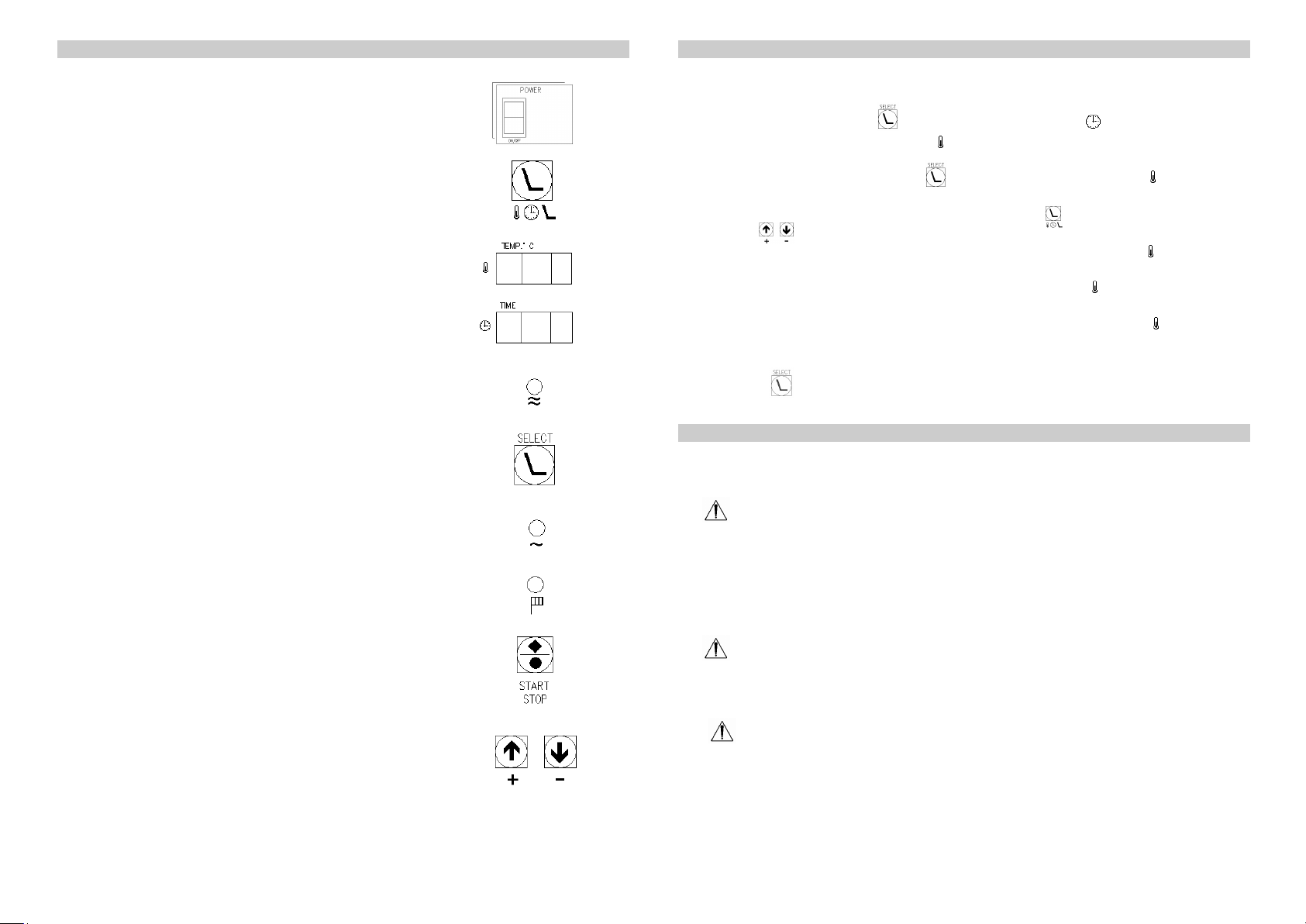
“CPS CONTROL PANEL” KEY
Pos. 7 Switch for starting and stopping
device's working (ON/OFF)
Pos. 8 Switch for setting time and temperature (SET)
Pos. 9 Temperature Display (TEMP.°C)
Pos. 10 Timer Display (TIME)
Pos. 11 Led “CONTINUOUS CYCLE running”
Pos. 12 Switch for setting “CONTINUOUS CYCLE running”.
Pos. 13 Led “resistances”
Pos. 14 Led “TIME-PROGRAMMED running”
Pos. 15 Switch for starting and stopping
“ TIME-PROGRAMMED running”
Pos. 16 Switch for setting time and temperature of the
sterilization cycle.
The device has also a continuos-cycle running. For use this kind of running proceed up to
point 6 of the procedure for time-programmed running described above.
Proceed as the following:
7. Press the button SELECT (Pos. 12). The display TIME (Pos. 10) shall indicate
OFF while the display TEMP. °C (Pos. 9) shall indicate the set temperature during
the last running.
8. On releasing the button SELECT (Pos. 12) the display TEMP.°C (Pos. 9) shall
show the ward ECL (Electronic-Compensation-Low). If it is required to change the
temperature (within 10°C), press the button SET (Pos. 8) and then using the
buttons (Pos. 16) for set the desired new value.
9. Once programmed the new temperature, on the display TEMP.°C (Pos. 9) shall
appear the ward ECL that shall remain visualised until the set temperature is reached.
10. When the set temperature is reached on display TEMP.°C (Pos. 9) shall appear the
ward ECH (Electronic-Compensation-High).
11. At the end of the internal compensation working on display TEMP.°C (Pos. 9) shall
appear the current internal temperature that persist with no time limit.
12. To terminate the sterilization procedure in continuous cycle running press the button
SELECT (Pos. 12).
If change of heating procedure is required, re-check each time set parameters since the
two systems (time-programmed and continuos cycle running) have memories
independent from each other.
In case of power cut-off while sterilization procedures has initiated, on return of
power the system shall compare the present temperature with the temperature at the
moment of power cut-off. If, temperature has dropped more than 5°C, compensation
procedure shall automatically be restored and, in case of timed procedure, preprogrammed time shall be re-activated. If, on the other hand, the temperature has not
dropped below 5°C, the procedure shall re-start regularly as though nothing has
happened.
In the event sterilized materials cause eventual release of dangerous gasses, it shall
be necessary the use of suction system to neutralise unwanted fumes (check the point
“consented uses” on page 9 regarding materials which can be heated and at any rate
avoid use of soaked material with toxic or harmful substances).
As the device heats up, avoid immission of substances or elements about which
reaction to heat is unknown, in order to avoid explosions, implosions or emissions of
toxic gasses.
CONTINUOS -CYCLE RUNNING
*** PLEASE NOTE ***
3 8
Page 5
TIME – PROGRAMMED RUNNING
(continued on)
10. To activate the time-programmed sterilization running, press the button
START/STOP (Pos. 15). In this way the green LED (Pos. 14) will light up and
the set temperature shall appear on the display TEMP.°C (Pos. 9). If the button
START/STOP (Pos. 15) is kept pressed, the temperature shall remain visualised on
the display until the button is released. After releasing the button STAR/STOP (
Pos. 15), the green LED “resistances” (Pos. 13) will light up and display
TEMP.°C (Pos. 9) show the ward ECL (Electronic-Compensation-Low). This
indication shall remain until set temperature is reached.
11. On reaching the set temperature the display TEMP.°C (Pos. 9) shall show the
ward ECH (Electronic-Compensation-High).
12. At the end of the internal compensation phase, the display TEMP.°C (Pos. 9) shall
show the current internal temperature and shall begin the countdown, shown by the
blinking of the decimal point (last value on the right) on the display TIME (Pos.
10).
13. Once sterilization cycle time is terminated, the green LED (Pos. 14) shuts itself
automatically.
TECHNICAL SPECIFICATION
Models: A3-216-400 A3-217-535
Loaded Chamber 3 kg 4 kg
External sizes:
Width mm 570 705
Height mm 400 475
Depth mm 345 450
Internal Sizes:
Width mm 405 535
Height mm 210 345
Depth mm 255 320
Weights:
Net weight kg. 13 kg 22 kg
Gross weight kg. 15 kg 25 kg
Electrical Characteristics:
Nominal tension (Voltage) 230 V 230 V
Nominal power (Watt) 450 W 950 W
Nominal frequency (Hz) 50/60 Hz 50/60 Hz
Net’s fuses (mm 5x20) F5A-250 V F5A-250 V
The device is in conformity to electrical safety norms provided for by the normative
institutes and supplied with bipolar plug which assures perfect electrical grounding.
*** ATTENTION ***
In the adjustment phase, the green LED (Pos. 13) indicates the activation of the
resistances for maintaining the temperature programmed. In case of abnormality of the
driving system of the resistances, on display TIME (Pos. 10), the indication FAL is
NON-COMPLIANCE WITH INSTRUCTIONS DESCRIBED IN THIS BOOKLET SHALL
FREE COMPANY TITANOX S.R.L. FROM ANY LIABILITY.
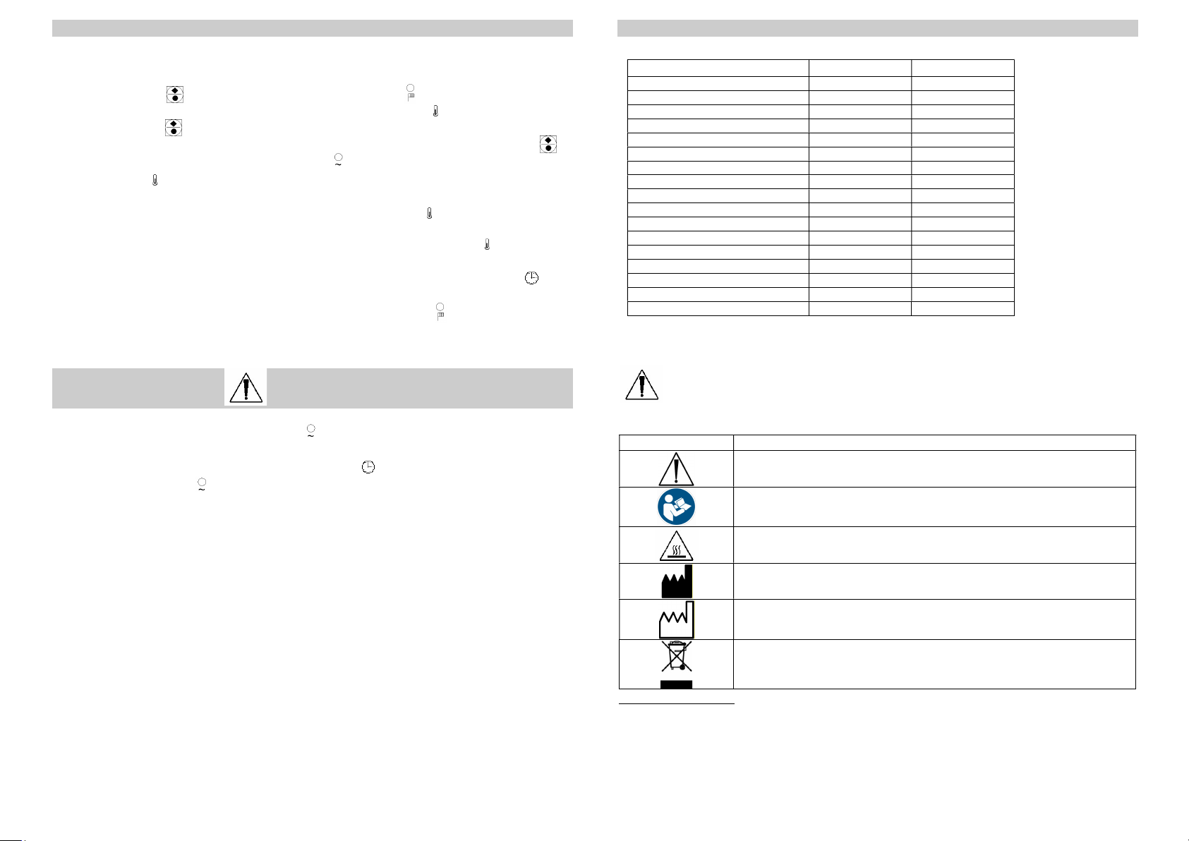
SYMBOLS MEANING
Warning !
shown and the green LED (Pos. 13) shall remain off.
See the annexed documentation
Caution! Hot surface (max. 210 °C)
It points the Manufacturer’s name
This symbol, together with the year, points the production date
RAEE symbol to handle electrical and electronical devices wastes
Available operation:
TIME-PROGRAMMED: timer programmable up to 4 hours
CONTINUOUS CYCLE: manual (without timer)
7 4
Page 6

ENVIRONMENTAL CONDITIONS
Ambient temperature from 5 to 40° C.
Relative humidity max. 80% for temperatures up to 31° C with linear decrease up to
50% at the temperature of 40° C condensing included.
Atmospheric Pressure from 500 to 1060 hPa.
Voltage supply variation not higher than 10%.
Value of transitory over-voltage in conformity to the installation category (which
provides for 2500V).
INSTALLATION
The device has been calibrated and tested at factory and as such does not require any
further calibration or adjustments before installation and start-up.
Unpack the device and follow the next advices:
1. Position the device on a levelled flat, hard and smooth surface, established with non-
infiammable material.
2. Allow space not lower than 10 cm from walls and surrounding furniture.
3.
Do not install the device nearby water sinks or similar to avoid contacts with water
or substances which could cause electrical short-circuit to the system.
4. Install the device in a well aerated location, not near windows or external doors which
could cause an unnatural circulation of the air inside the device and therefore
compromise its correctly running.
5.
Do not install the device nearby heat sources or near other electrical devices.
6. Install the device in such a way that the power cable is never twisted or bent, but it
should connect to the socket free and unhindered. Avoid to positioning the power cable
nearby heat sources or other devices that shall caused damage on it in a long run.
7. In the event the device is placed on a trolley, always check that the lower part of the
device is not enclosed or hindered, as to allow continuos and sufficient ventilation.
Once the device is correctly installed and power cable connected, it’s ready for use.
The device is designed for use in internal locations.
The device is not designed for use in presence of gasses or explosive vapours.
No water or other liquids should be poured into device neither on its base.
Before any cleaning or maintenance actions, the power cable must always first be
removed.
Make sure that the electrical system has electrical grounding and that it’s in conformity
to the safety norms in the country of installation.
Do not remove any label or plate, in case of need, ask for more.
Always insist on original spare parts.
Do not open the door of the device until the thermometer of the internal temperature do
not indicate a temperature lower than 30°C.
Medical devices, before being placed in the sterilizer, should be washed and dried. The
residual water steam may create deposits on the probes and resistances by altering the
precision.
1. Insert the supplied connection socket of the mains cable in the plug of the device
(Pos. 2) and the feeder- plug in the wall mains socket, after checking the voltage value.
2. Place materials to be sterilized inside the device
3. Lock up the door. (Pos. 5)
4. Keep the air-inlets half-opened (Pos. 3) to allow a better circulation of the air inside
the device and to distribute the heat even to the corners and hidden spaces. Close the
above air-inlets only at the end of the sterilization cycle in order to seal the device and
to keep the material inside in temperature for a long time.
5. The device is switch on by pressing the button ON/OFF (Pos. 7).
6. Once the device is on, the display TEMP. °C (Pos. 9) shows the current internal
temperature, while the display TIME (Pos. 10) shows the last set timing for
sterilization cycle.
7. For programming or changing sterilization time, press the button SET (Pos. 8).
In this way the display TIME (Pos. 10) begin to blink. Use the buttons (Pos.
16) to change the value shown, up to sterilization time required. The length, expressed
in minutes, can be change from 1 to 250. At the end of blinking, the time shown shall
be automatically memorised ( ATTENTION! Let the blinking end by itself).
8. To show the set heating temperature press the button SET (Pos. 8).
9. To set or change temperature press SET (Pos. 8) for two consecutive times. In this
way the temperature display TEMP.°C (Pos. 9) will begin to blink. Use the
buttons (Pos. 16) to change the value shown, up to the temperature required.
The temperature can be changed from 1 to 200°C. At the end of blinking, the
temperature shown shall automatically be memorised and shall again be shown the
current internal temperature ( ATTENTION! Let the blinking end by itself).
SAFETY WARNINGS
TIME – PROGRAMMED RUNNING
(to be continued)
5 6
 Loading...