

ri-scope®
ng
s
ri-scope
®
L
ri-derma
Gebrauchsanweisung
Diagnostische Instrumente
Instructions
Diagnostic Instruments
Mode d’ emploi
Instruments diagnostiques
isu
nstrumente
ument
gnostiques
®
Instrucciones para el uso
Instrumentos diagnósticos
Инструкция по эксплуатации
Диагностические приборы
Istruzioni per I’ uso
Strumenti diagnostici
ra el uso
iagnósticos
эксплуатации
ие приборы
uso
ostici

ENGLISH
1.Important information to observe prior to initial use
You have purchased a high quality Riester diagnostic instrument set manufactured in compliance with Directive 93/42/EEC for medical devices and subject to stringent quality control procedures at all stages. The excellent quality
guarantees you reliable diagnoses. The use of the Riester battery handle for
the ri-scope
scribed in our Operating Instructions. Please read the Operating Instructions
carefully before initial use and retain them for future reference. Should you have
any questions, we or the representative responsible for Riester products are
available for you at all times. Please find our address on the last page of these
Operating Instructions. We would be pleased to provide you with the address of
our representative on request. Please note that at the instruments described in
these Operating Instructions are exclusively suitable for use by properly trained
persons. The operation otoscope in the Vet-I instrument set is an instrument
exclusively produced for veterinary medicine and therefore bears no CE mark.
Please also note that the faultless and safe function of our instruments can only
be ensured if the instruments as well as their accessories used are exclusively
from Riester.
Safety precautions:
Caution: Observe the Operating Instructions!
Device double-earthed
Classification
Type-B applied part - otoscope head with speculum
2. Battery handles and initial use
2.1. Purpose
The Riester battery handles described in these Operating Instructions serve to supply the instrument heads with power (the lamps are contained in the respective instrument heads). They
also serve as holders.
2.2. Battery handle range
All the instrument heads described in these Operating Instructions fit on the
following battery handles and can therefore be individually combined. Furthermore, all instrument heads fit the handles of the ri-former
CAUTION: LED instrument heads are only compatible with the ri-former
gnostic station above a certain serial number. You may obtain specifications on
the compatibility of your diagnostic station on request.
For ri-scope
praktikant, de luxe
a) Type C battery handle with 2.5 V rheotronic®. To operate these battery
handles, you require 2 commercial Type C Baby alkaline batteries (IEC
standard designation LR14) or a 2.5 V ri-accu
ri-accu
b) Type C battery handle with 3.5 V rheotronic
you require two CR 123A type commercial lithium batteries (Please note:
only with reducing sleeve and LDO controller) or a ri-accu
handle with the Riester ri-accu
ri-charger
c) Type C chargeable battery handle with or without sensomatic® 2.5 V or 3.5 V
function with rheotronic
handle is available as a 2.5 V or 3.5 V model and can be ordered for 230 V or
120 V operation. Please note that the handle can only be used with the
Riester ri-accu
d) Type AA battery handle with 2.5 V rheotronic
handles, you require two commercial Type AA Baby alkaline batteries (IEC
standard designation LR6) or a ri-accu
ri-accu
e) Type AA battery handle with 3.5 V rheotronic
you require two CR 123A type commercial lithium batteries (Please note:
only with an LDO controller)or a ri-accu
Riester ri-accu
2.3. Inserting and removing batteries and rechargeable batteries
Handle types (2.2 a, b, d and e)
Screw off the handle cover on the lower part of the handle. Depending on which
handle you have purchased and for what voltage (see 2.2), insert the respective
batteries or rechargeable battery into the casing such that the positive end point
towards the top of the handle. There is also an arrow next to the plus symbol
on the rechargeable battery, which shows you the direction to insert into the
handle. Screw the handle cover onto the handle again.
CAUTION: For lithium batteries (only for type-C battery handles) you need a
reducing sleeve (item no.: 12652) + LDO controller (item no.: 12653)
®
and ri-derma® instrument heads and their accessories is de-
®
wall model.
®
L otoscopes, ri-scope®L ophthalmoscopes, perfect, E.N.T.,
®
, Vet, slit and spot retinoscopes, ri-vision
®
®
can only be charged in the Riester ri-charger®.
®
®
L.
®
or ri-accu®L.
®
can only be charged in the Riester ri-charger®.
®
L can only be charged in the Riester ri-charger®L.
L can only be charged in the Riester
®
to charge from the mains 230 V or 120 V. The
. The handle with the Riester
®
To operate this battery handle
®
. To operate these battery
®
2.5 V. The handle with the Riester
®
To operate this battery handle
®
L 3.5 V. The handle with the
®
®
L 3.5 V. The
®
dia-
15

Handle C
For refitting:
Twist off the cap of the handle on the lower part of the handle.
For lithium batteries, the reducing sleeve is inserted into the handle shell with
the end where the spring tensioning ring is seated facing forward, and the LDO
controller is inserted in the direction indicated by the printed arrow. The lithium
batteries are inserted with the positive poles facing toward the upper part of the
handle. Screw the cap of the handle firmly back onto the handle.
Handle AA
For refitting:
Twist off the cap of the handle on the lower part of the handle.
For lithium batteries, the LDO controller is inserted in the direction indicated
by the printed arrow. The lithium batteries are inserted with the positive poles
facing toward the upper part of the handle. Screw the cap of the handle firmly
back onto the handle.
Remove the batteries by firstly screwing off the battery handle cover and then
shaking the handle a little.
Prior to initial use, the rechargeable batteries (in the Riester battery handle)
must be charged in the Riester ri-charger®. Separate operating instructions
are included with every charger and must be observed.
Handle types (2.2. c)
Prior to initial use of the plug-in handle, it should be charged for up to 24 hours
in the mains socket.
CAUTION: The plug-in handle (only for NiMH rechargeable batteries) must not
be charged for longer than 24 hours.
Screw off the handle cover on the lower part of the handle. Depending on which
handle you have purchased and for what voltage (see 2.2), insert the respective
rechargeable batteries into the handle casing. For 2.5 V rechargeable batteries
take care that the battery is inserted into the handle with the plus end towards
the top of the handle; you will also find an arrow next to plus symbol which
shows you the direction to insert into the handle. It is irrelevant in which direction 3.5 V rechargeable batteries are inserted. Screw the handle cover tightly
onto the handle again. Unscrew the lower part of the handle counter clockwise.
The mains socket pins become visible. Round pins are for 230 V mains operation, flat pins are for 120 V mains operation Plug the lower part of the handle into
the mains socket for charging. Caution: The handle must never be in the mains
socket when the rechargeable batteries are replaced! If you wish to replace the
®
battery, unscrew the battery handle cover on the lower part of the
ri-accu
handle counter clockwise. Remove the ri-accu
le by shaking down the handle downwards a little. Insert the ri-accu
into the battery handle. For 2.5 V rechargeable batteries, take care that the battery is inserted into the handle with the plus end towards the top of the handle;
you will also find an arrow next to plus symbol which shows you the direction to
insert into the handle. It is irrelevant in which direction 3.5 V rechargeable batteries are inserted. Screw the battery cover clockwise onto the handle. Technical
data: Either 230 V or 120 V
CAUTION:
• If you do not plan to use the device for a long time or if you take it on a
journey, remove the batteries and rechargeable batteries from the handle.
• New batteries should be inserted once the light intensity of the instrument
becomes weaker.
• To obtain the best possible light output we recommend always fitting high
quality batteries (as described in 2.2).
• If you suspect that liquid or moisture could have entered the handle, it must
not be charged under any circumstances. This could lead to a life-threa tening electric shock, especially in the case of plug-in handles.
• To extend the service life of the ri-accu
should only be charged once the light intensity of the instruments has
become weaker.
Waste disposal: Please note that batteries and rechargeable batteries must be
disposed of as special waste. You can obtain the relevant information from your
local authority or from your local environmental advisor.
2.4. Fitting instrument heads
Fit the required instrument head on the receptacle on the upper part of the
handle such that the two recesses of the lower part of the instrument head fit
on the two protruding guide studs on the battery handle. Press the instrument
head lightly on to the battery handle and screw the handle clockwise as far as it
goes. The head is removed by screwing counter clockwise.
2.5 Switching Type C and AA battery handles on and off
Activate the instrument by turning the switching ring on the top of the handle
clockwise direction. To switch off the instrument turn the ring anti-clockwise
direction until the device is swithced-off.
®
2.6. rheotronic
With the rheotronic it is possible to modulate the light intensity for the C and
AA handles. Depending on how often you turn the switching ring clockwise or
anti-clockwise direction, the light intensity is stronger or weaker.
ATTENTION: At every switch-on of the battery handle the light intensity is at
100% Automatic safety switch-off after 180 seconds.
for adjusting the light intensity
®
battery from the battery hand-
®
battery, the ri-accu® battery
®
battery
16

Explanation of the symbol on the plug-in handle:
Caution: Observe the Operating Instructions!
3. ri-scope®L otoscope
3.1. Purpose
The Riester otoscope described in these Operating Instructions is produced for
illumination and examination of the auditory canal in combination with Riester
ear specula.
3.2 Fitting and removing ear specula
Either Riester disposable ear specula (blue colour) or reusable Riester ear
specula (black colour) can be fitted to the otoscope head. The size of the ear
specula is marked at the back of the speculum.
L1 and L2 otoscopes
Screw the speculum clockwise until noticeable resistance is felt. To remove the
speculum, screw the speculum counter clockwise.
L3 otoscope
Fit the chosen speculum on the chrome-plated metal fixture of the otoscope
until it locks into place. To remove the speculum, press the blue ejection button.
The speculum is automatically ejected.
3.3. Swivel lens for magnification
The swivel lens is fixed to the device and can be swivelled 360°.
3.4. Insertion of external instruments into the ear
If you wish to insert external instruments into the ear (e.g. tweezers), you have
to rotate the swivel lens (approx. 3-fold magnification) located on the otoscope
head by 180°. Now you can use the operation lens.
3.5. Pneumatic test
To perform the pneumatic test (= examination of the eardrum), you require a
ball, which is not included in the normal delivery package, but can be ordered
separately. The tube for the ball is attached to the connector. Now you can carefully insert the necessary volume of air into the ear canal.
3.6 Technical data of the lamp
Otoscope XL 2.5 V 2.5 V 750 mA mean life span 15h
Otoscope XL 3.5 V 3.5 V 720 mA mean life span 15h
Otoscope LED 3.5 V 3.5 V 28 mA mean life span 10000h
®
4. ri-scope
4.1. Purpose
The Riester ophthalmoscope described in these Operating Instructions is produced for the examination of the eye and the eyeground.
4.2. Lens wheel with correction lens
The correction lens can be adjusted on the lens wheel. The following correction
lenses are available:
L1 and L2 ophthalmoscopes
Plus: 1-10, 12, 15, 20, 40.
Minus: 1-10, 15, 20, 25, 30, 35.
L3 ophthalmoscope
Plus: 1-45 in single steps
Minus: 1-44 in single steps
The values can be read off in the illuminated field of view. Plus values are displayed in green numbers, minus values with red numbers.
4.3. Apertures
The following apertures can be selected with the aperture hand-wheel:
L1 ophthalmoscope
Semi-circle, small/medium/large circular aperture, fixation star, slit.
L2 ophthalmoscope
Semi-circle, small/medium/large circular aperture, fixation star and slit.
L3 ophthalmoscope
Semi-circle, small/medium/large circular aperture, fixation star, slit and grid.
Aperture Function
Semicircle: for examinations with turbid lenses
Small circle: to reduce reflections for small pupils
Medium circle: to reduce reflections for small pupils
Large circle: for normal examination results
Grid: for topographic determination of
retina changes
Light slit: to determine differences in level
Fixation star: to ascertain central of eccentric
fixation
L ophthalmoscope
17

4.4 Filters
Using the filter wheel, the following filters can be switched for each aperture:
L1 ophthalmoscope Red-free filter
L2 ophthalmoscope Red-free filter, blue filter and polarisation filter.
L3 ophthalmoscope Red-free filter, blue filter and polarisation filter.
Filter Function
Red-free filter: contrast enhancing to assess fine vascular changes, e.g.
retinal
bleeding
Polarisation filter: for precise assessment of tissue colours and to avoid
retinal reflections
Blue filter: for improved recognition of vascular abnormalities or
bleeding, for fluorescence ophthalmology
For L2 + L3, every filter can be switched to every aperture.
4.5. Focussing device (only with L3)
Fast fine adjustment of the examination area to be observed is achieved from
various distances by turning the focussing wheel.
4.6. Magnifying glass
A magnifying glass with 5-fold magnification is supplied with the ophthalmoscope set. This can be positioned between the instrument head and the area
under examination, as required. The area under examination is magnified accordingly.
4.7. Technical data on the lamp
XL 2.5 V ophthalmoscope: 750 mA average service life 15 h
XL 3.5 V ophthalmoscope: 690 mA average service life 15 h
LED 3.5 V ophthalmoscope: 29 mA average service life 10000 h
5. Slit and spot retinoscopes
5.1 Purpose
The slit/spot retinoscopes (also known as skiascopes) described in these Operating Instructions are produced to determine the refraction (ametropias) of the
eye
5.2. Initial use and function
Position the required instrument head on point of attachment on top section of
handle with both recesses of the instrument head bottom section being congruent with the two projecting guide cams of the battery handle. Press instrument
head lightly on battery handle and rotate handle in clockwise direction to the
stop. Remove head by rotating in counter-clockwise direction. Rotation and focusing of the slit and/or spot image may now be effected by the knurled screw.
5.3. Rotation
The slit or spot image may be rotated by 360° by the control. Each angle may be
directly read from the scale on the retinoscope.
5.4. Fixation cards
Fixation cards are suspended and fixed on the object side of the retinoscope into
the bracket for the dynamic skiascope.
5.5 Technical data of the lamp
Slit retinoscope HL 2.5 V 2.5 V 440 mA mean life span 15h
Slit retinoscope XL 3.5 V 3.5 V 690 mA mean life span 50h
Spot retinoscope HL 2.5 V 2.5 V 450 mA mean life span 15h
Spot retinoscope XL 3.5 V 3.5 V 640 mA mean life span 40h
6. Dermatoscope
6.1. Purpose
The ri-derma
duced for early identification of changes of skin pigmentation (malignant melanomas).
6.2. Initial use and function
Position the required instrument head on point of attachment on top section of
handle with both recesses of the instrument head bottom section being congruent with the two projecting guide cams of the battery handle. Press instrument
head lightly on battery handle and rotate handle in clockwise direction to the
stop. Remove head by rotating in counter-clockwise direction.
6.3. Focusing
Focus the magnifying glass by rotating the eyepiece ring.
6.4. Skin adapters
Two skin adapters are supplied:
1) Including a scale of 0 - 10 mm for measuring melanotic skin changes, such
as malign melanoma.
2) Without a scale Both skin adapters are suitable for multiple removal and
replacement.
®
dermascope described in these Operating Instructions is pro-
18

6.5 Technical data of the lamp
®
XL 2.5 V 2.5 V 750 mA mean life span 15h
ri-derma
®
XL 3.5 V 3.5 V 690 mA mean life span 15h
ri-derma
®
LED 3.5 V 3.5 V 28 mA mean life span 10000h
ri-derma
7. Bent-arm illuminator
7.1. Purpose
The bent-arm illuminator described in these Operating Instructions is produced
for illuminating the oral cavity and the pharynx.
7.2. Initial use and function
Position the required instrument head on point of attachment on top section of
handle with both recesses of the instrument head bottom section being congruent with the two projecting guide cams of the battery handle. Press instrument
head lightly on battery handle and rotate handle in clockwise direction to the
stop. Remove head by rotating in counter-clockwise direction.
7.3 Technical data of the lamp
bent-arm illuminator XL 2.5 V 2.5 V 750 mA mean life span 15h
bent-arm illuminator XL 3.5 V 3.5 V 690 mA mean life span 15h
bent-arm illuminator LED 3.5 V 3.5 V 28 mA mean life span 10000h
8. Nasal speculum
8.1. Purpose
The nasal speculum described in these Operating Instructions is produced for
illumination and therefore examination of the inside of the nose.
8.2. Initial use and function
Position the required instrument head on point of attachment on top section of
handle with both recesses of the instrument head bottom section being congruent with the two projecting guide cams of the battery handle. Press instrument
head lightly on battery handle and rotate handle in clockwise direction to the
stop. Remove head by rotating in counter-clockwise direction. For two modes
of operation:
a) Fast expansion Push set screw on instrument head down with your thumb.
This setting does not allow changes in the position of the speculum legs.
b) Individual expansion Rotate set screw in clockwise direction until the
required expansion width is obtained. Close legs again by turning screw in
clockwise direction.
8.3. Swivel lens
The nasal speculum is equipped with a swivel lens of approx. 2.5X enlargement
which may be simply pulled out and/or replaced in the opening provided on the
nasal speculum.
8.4 Technical data of the lamp
nasal speculum XL 2.5 V 2.5 V 750 mA mean life span 15h
nasal speculum XL 3.5 V 3.5 V 720 mA mean life span 15h
nasal speculum LED 3.5 V 3.5 V 20 mA mean life span 10000h
9. Blade holder
9.1. Purpose
The blade holder described in these Operating Instructions is produced for examination of the oral cavity and pharynx in combination with commercial wooden
and plastic blades.
9.2. Initial use and function
Position the required instrument head on point of attachment on top section of
handle with both recesses of the instrument head bottom section being congruent with the two projecting guide cams of the battery handle. Press instrument head lightly on battery handle and rotate handle in clockwise direction
to the stop. Remove head by rotating in counter-clockwise direction. Insert a
commercial wooden or plastic tongue blade into the aperture below the light
opening up to the stop. The tongue blade is easy to remove after examination
by actuating the ejector.
9.3 Technical data of the lamp
blade holder XL 2.5 V 2.5 V 750 mA mean life span 15h
blade holder XL 3.5 V 3.5 V 720 mA mean life span 15h
blade holder LED 3.5 V 3.5 V 20 mA mean life span 10000h
10. Laryngeal mirrors
10.1. Purpose
The laryngeal mirrors described in these Operating Instructions are produced
for mirroring or examination of the oral cavity and pharynx in combination with
the Riester bent-arm illuminator.
10.2. Initial use
Laryngeal mirrors may only be used in combination with the bent arm illuminator, thus ensuring maximum lighting conditions. Take two laryngeal mirrors and
fix them in the required direction on the bent-arm illuminator.
11. Operation otoscope for veterinary medicine
11.1. Purpose
The Riester operation otoscope described in these Operating Instructions is
produced exclusively for use on animals and for veterinary medicine and there-
19

fore bears no CE mark. It can be used for illumination and examination of the
auditory canal, as well as for minor operations in the auditory canal.
11.2. Attachment and removal of ear specula in veterinary medicine
Position the required speculum on the black bracket of the operating otoscope,
with the recess of the speculum fitting into the guide of the bracket. Attach
speculum by rotating in anti-clockwise direction.
11.3. Swivel lens for enlargement
The operating otoscope comprises a small magnifying lens to be swivelled at an
angle of 360° for a maximum enlargement of approx. 2.5X.
11.4. Insertion of external instruments into the ear
The operation otoscope is designed to be open so that external instruments can
be inserted into the animal ear.
11.5 Technical data of the lamp
Operating otoscope HL 2.5 V 2.5 V 680 mA mean life span 20h
Operating otoscope XL 3.5 V 3.5 V 700 mA mean life span 20h
12. Operation otoscope for human medicine
12.1. Purpose
The Riester operation otoscope described in these Operating Instructions is
produced for illumination and examination of the auditory canal and for insertion of external instruments into the auditory canal.
12.2 Attachment and removal of ear specula for human medicine
Place the desired speculum onto the black holder of the operation otoscope so
that the recess on the speculum fits into the guide of the holder. Fix the speculum by turning it in a counter-clockwise direction.
12.3 Swivel lens for magnification
There is a small magnification lens which can be swivelled 360° on the operation otoscope with approx. 2.5-fold magnification.
12.4. Insertion of external instruments into the ear
The operation otoscope is designed so that external instruments can be inserted into the ear.
12.5 Technical data of the lamp
Operating otoscope HL 2.5 V 2.5 V 680 mA mean life span 20h
Operating otoscope XL 3.5 V 3.5 V 700 mA mean life span 20h
13. Replacing the lamp
L1 otoscope
Remove the specula fitting from the otoscope. Screw out the lamp counter
clockwise. Screw in the new lamp clockwise and replace the specula fitting.
®
L2, L3 otoscopes, ri-derma
blade holder
Screw the instrument head off the battery holder. The lamp is located at the
base of the instrument head. Pull the lamp out of the instrument head with
thumb and forefinger or a suitable tool. Insert a new lamp.
Ophthalmoscopes
Remove the instrument head from the battery holder. The lamp is located at the
base of the instrument head. Remove the lamp from the instrument head with
thumb and forefinger or a suitable tool. Insert a new lamp.
CAUTION: The pin on the lamp must be inserted into the guide groove on the
instrument head.
Veterinary/human operation otoscope
Screw the lamp out of the fixture in the operation otoscope and screw in a new
lamp.
14. Instructions for care
General information
Cleaning and disinfection of the medical devices serves to protect the patient,
the user and third parties and to preserve the value of the medical devices.
Due to the product design and the materials used, no defined limit can be specified for the maximum number of reprocessing cycles that can be carried out.
The life span of the medical devices is determined by their function and by gentle handling of the devices.
Defective products must undergo the reprocessing procedure described before
being returned for repair.
Cleaning and disinfection
The instrument heads and handles can be cleaned externally with a moist cloth
until visually clean. Wipe-disinfection as specified by the disinfectant manufacturer. Only disinfectants with proven efficacy should be used, taking into account
the national requirements.
After disinfection, wipe the instrument down with a moist cloth to remove possible disinfectant residues.
The components that come into contact with the skin (ri-derma
, bent-arm illuminator, nasal speculum and
®
) can be rub-
20

V
bed down with alcohol or a suitable disinfectant.
PLEASE NOTE!
• Never immerse the instrument heads and handles in liquids! Take care to
ensure that no liquids get inside the casing!
• This item is not approved for automated reprocessing and sterilization.
These procedures cause irreparable damage!
Sterilization
a) Reusable ear specula
The ear specula can be sterilized in the steam sterilizer at 134°C with 10 minutes hold time.
b) Single-use ear specula
For single use only
WARNING: Repeated use can cause infections.
15. Spare parts and accessories
You can find a detailed list in our Instruments for E.N.T. and Ophthalmologic
Instruments brochure, which you can download at www.riester.de.
16. Maintenance
These instruments and their accessories do not require any specific maintenance.Should an instrument have to be examined for any specific reason whatsoever, please return it to the Company or an authorised Riester dealer in your
area. Addresses to be supplied on request.
17. Notices
Ambient temperature: 0°C to +40°C
Relative humidity: 30% to 70% non-condensing
Transport and storage
temperature: -10°C to +55°C
Relative humidity: 10% to 95% non-condensing
18 Electromagnetic compatibility
Medical electrical equipment is subject to special precautionary measures with
regard to electromagnetic compatibility (EMC).
Portable and mobile high-frequency communication equipment can influence
medical electrical equipment. This ME device is intended for operation in an
electromagnetic environment as specified below. The user of the device should
ensure that it is operated in such an environment.
The ME device must not be used directly next to or arranged in a stack with
other devices. If the device has to be operated near to or in a stacked arrangement with other devices, then the ME device should be monitored in order
to verify that it operates as intended in this arrangement. This ME device is
intended exclusively for use by professional medical staff. This device can cause
radio interference and can disrupt the operation of equipment nearby. Suitable
remedial measures, such as for instance re-alignment, re-arrangement of the
ME device or shielding, can become necessary.
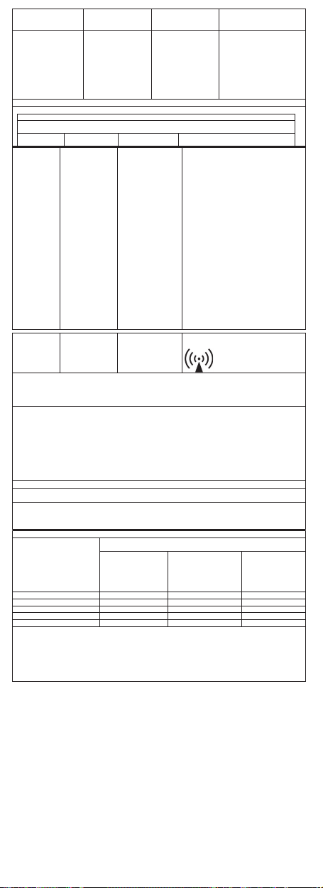
Guidelines and manufacturer's declaration - electromagnetic emissions
The ri-scope® L is intended for operation in an electromagnetic environment as specified below. The
customer or the user of the ri-scope® L should ensure that it is used in such an environment.
Emission measurements
HF emissions according to
CISPR 11
HF emissions according to
CISPR 11
Harmonics emissions
according to EC61000-3-2
Voltage fluctuation / flicker
emissions according to
IEC61000-3-3
The ri-scope® L is intended for operation in an electromagnetic environment as specified below. The customer or the
user of the ri-scope® L should ensure that it is used in such an environment.
Immunity tests IEC 60601 test level Compliance level
Electrostatic discharge
(ESD)
according to IEC61000-4-2
Fast transient electrical
interference/bursts
according to IEC61000
Surges
-4-5
IEC61000
oltage dips, short-time
interruptions and
fluctuations in the supply
voltage according to
-4-11
IEC61000
± 6 kV contact discharge
± 8 kV air discharge
± 2 kV for power lines
± 1 kV for input and
-4-4
output lines
± 1 kV voltage phase-tophase
± 2 kV voltage phase-toearth
<5% U
(>95 % drop in UT)
for 0.5 cycles
40% U
(60 % drop in UT)
for 5 cycles
70 % U
(30 % drop in UT)
for 25 cycles
Compliance
Group 1
Class B
Not applicable
Not applicable
T
T
T
Electromagnetic environment - guidelines
The ri-scope® L employs HF energy solely for an
internal function. Its HF emission is therefore
very low and it is unlikely that neighboring
electronic devices will be affected by
interference.
The ri-scope® L is intended for use in all
facilities, including living quarters and such as
are directly connected to a public power supply
that also supplies buildings that are used for
residential purposes.
± 6 kV contact discharge
± 8 kV air discharge
Not applicable The quality of the supply voltage
Not applicable The quality of the supply voltage
Not applicable
Electromagnetic environment -
Floors should be made of wood
or concrete or be covered with
ceramic tiles. If the floor is
covered with a synthetic material,
the relative air humidity must be
at least 30%.
should correspond to that of a
typical business or hospital
environment.
should correspond to that of a
typical business or hospital
environment.
The quality of the supply voltage
should correspond to that of a
typical business or hospital
environment
guidelines
21
<5% U
T
(>95 % drop in UT)
Magnetic field at the mains
frequency (50Hz)
according to IEC61000-4-8
Note - UT is the alternating supply voltage prior to application of the test level.
The ri-scope® L model is intended for operation in the electromagnetic environment specified below. The
customer or the user of the ri-scope® L should ensure that it is used in such an environment.
Immunity test IEC 60601
ted HF
Conduc
interference
according to
-4-6
IEC61000
Radiated HF
rference
ording to
-4-3
61000
for 5 s
3 A/m 3 A/m If image disturbances occur, the
Guidelines and manufacturer's declaration - electromagnetic immunity
test level
3 Vrms
150 kHz to 80MHz
3 V/m
80 MHz to 2.5GHz
ri-scope® L may have to be
placed further away from the
sources of mains-frequency
magnetic fields, or magnetic
shielding may have to be
installed: the mains-frequency
magnetic field should be
measured at the intended set-up
site in order to ensure that it is
small enough.
Compliance level Electromagnetic environment - guidelines
Portable and mobile radio equipment should
not be used within a distance from the riscope® L, including cables, that is less than
the recommended safety distance as
calculated by the equation that is appropriate
for the transmission frequency.
Recommended safety distance:
Not applicable
10 V/m
d = 1.2P
d = 1.2P 80 MHz to 1000 MHz
d = 2.3P 1400 MHz to 2.5 GHz
3 V/m
where P is the nominal power of the
transmitter in Watts (W) as specified by the
manufacturer of the transmitter, and d is the
recommended safety distance in meters (m).
The field strength of stationary radio
transmitters should be less than the
compliance level
verified by an on-site test
Interference is possible in the vicinity of
equipment marked with the following symbol
b
at all frequencies as
a
Note 1: At 80 MHz and 80
Note 2: These guidelines may not apply in all situations. The propagation of electromagnetic waves is influenced
by reflection and absorption by buildings, objects and people.
a
The field strength of stationary transmitters, such as base stations of wireless telephones and mobile field
radio services, amateur radio stations, AM and FM radio and television transmitters cannot be precisely
determined theoretically in advance. In order to determine the electromagnetic environment due to stationary
HF transmitters, an investigation of the location is advisable. If the field strength determined at the location of
the ri-scope® L exceeds the compliance level indicated above, then the ri-scope® L must be monitored with
regard to its normal operation at each place where it is used. If unusual performance characteristics are
observed, additional measures such as re-alignment of the ri-scope® L or its removal to another place may be
necessary.
b
In the frequency range of 150 kHz to 80 MHz, the field strength should be smaller than 3 V/m.
Recommended safety distances between portable and mobile HF communication devices and the riscope® L
The ri-scope® L is intended for operation in an electromagnetic environment in which the radiated HF
interference is monitored. The customer or user of the ri
interference by observing minimum distances between portable and mobile HF communication equipment
(transmitters) and the ri-scope® L as recommended below, depending on the maximum output power of the
communication equipment.
Nominal power of the
For transmitters whose nominal power is not indicated in the table above, the distance can be determined using
the equation belonging to the respective column, where P is the nominal power of the transmitter in Watts (W)
as specified by the manufacturer of the transmitter.
Note 1: At 80 MHz and 1400 MHz, the distance for the higher frequency range applies.
Note 2: These guidelines may not apply in
by reflection and absorption by buildings, objects and people.
0 MHz, the higher value applies.
-scope® L can help prevent electromagnetic
transmitter
W
0.01 0.12 0.23
0.1 0.38 0.73
1 1.2 2.3
10 3.8 7.3
100 12 23
Safety distance that applies to the transmitter frequency
150 kHz to 80 MHz
Not applicable
all situations. The propagation of electromagnetic waves is influenced
m
80 MHz to 1000 MHz
d = 1.2P
1400 MHz to 2.5GHz
d = 2.3P
22

Rudolf Riester GmbH
P.O. Box 35 | Bruckstraße 31 | DE - 72417Jungingen | Germany
Tel.: (+49) +7477-9270-0 | Fax.: (+49) +7477-9270-70
E-Mail: info@riester.de | www.riester.de
99220 Rev.D 2013-08 • Änderungen vorbehalten • Subject to alterations • Sous réserve de modifications • Sujeto a modificaciones • Возможны изменения • Con riserva di apportare modifiche
 Loading...