

Page 1
Gima S.p.A.
Via Marconi, 1 - 20060 Gessate (MI) Italy
gima@gimaitaly.com - export@gimaitaly.com
PROFESSIONAL MEDICAL PRODUCTS
www.gimaitaly.com
PULSOXIMETRO OXY 110
OXY 110 PULSE OXIMETER
PULSIOXÍMETRO OXY 110
OXYMÈTRE DE POULS OXY 110
Manuale d’uso - User manual
Manuel de l’utilisateur - Guía de uso
ATTENZIONE: Gli operatori devono leggere
e capire completamente questo manuale
prima di utilizzare il prodotto.
ATTENTION: The operators must carefully read
and completely understand the present manual
before using the product.
AVIS: Les opérateurs doivent lire et bien
comprendre ce manuel avant d’utiliser le produit.
ATENCIÓN: Los operadores tienen que leer y entender
completamente este manual antes de utilizar el producto.
M34341-M-Rev.2.02.20
34341 / SP-20
Shenzhen Creative Industry Co., Ltd.
Floor 5, BLD 9, BaiWangxin High-Tech Industrial Park,
Songbai Road, Xili Street, Nanshan District,
518110 Shenzhen, P.R. China
Made in China
Shanghai International
Holding Corp. GmbH (Europe)
Eiffestrasse 80, 20537, Hamburg, Germany
0123
Page 2

39
ENGLISH
Table of Contents
1 Overview ...................................................................................................... 40
1.1 Appearance ............................................................................................40
1.2 Product Name and Model ......................................................................42
1.3 Structure ................................................................................................. 42
1.4 Features .................................................................................................. 42
1.5 Intended Use ..........................................................................................42
1.6 Working Environment ..............................................................................42
2 Power Supply .............................................................................................. 43
3 Make Measurement .................................................................................... 45
3.1
SpO2 Measurement ......................................................................................45
3.2 Temperature Measurement (optional) .................................................... 46
4 Operation ..................................................................................................... 47
4.1 Power on/off the Oximeter......................................................................47
4.2 Default Display Screen ...........................................................................48
4.3 Menu ....................................................................................................... 49
4.4 Record ................................................................................................... 58
5 Technical Specications ............................................................................ 61
6 Over-limit Indication ...................................................................................63
6.1 Limit settings ..........................................................................................63
6.2
Over-limit indication sound mute setting .......................................................63
7 Packing List ................................................................................................. 63
8 Repair and Maintenance ............................................................................ 64
8.1 Maintenance ........................................................................................... 64
8.2 Cleaning and Disinfecting Instruction ..................................................... 64
9 Troubleshooting .......................................................................................... 65
10 Frequently Asked Questions ...................................................................... 66
Appendix ..........................................................................................................67
I. Key of Symbols .......................................................................................... 67
II. Common Knowledge ................................................................................ 69
Page 3
1 Overview
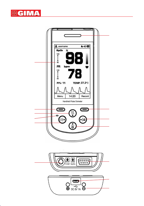
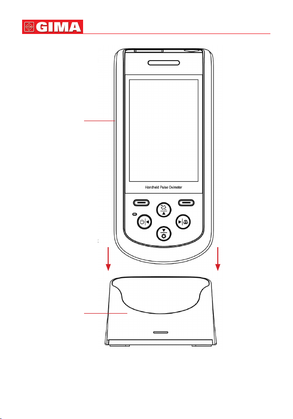
1.1 Appearance
Display screen
ENGLISH
40
Alert
indicator
Menu/Conrm
Auto-rotate /Up
Power indicator
Power/Left
Figure 1.1 Front view
TEMP:
Temperature
probe
connector
Figure 1.2 Upper-side view
Figure 1.3 Bottom side view
Record/Back
Right /Sound
Setting/Down
SpO2:
SpO2 probe
connector
USB connector
DC power input
contact shoes
with polarity
indication
Page 4
41
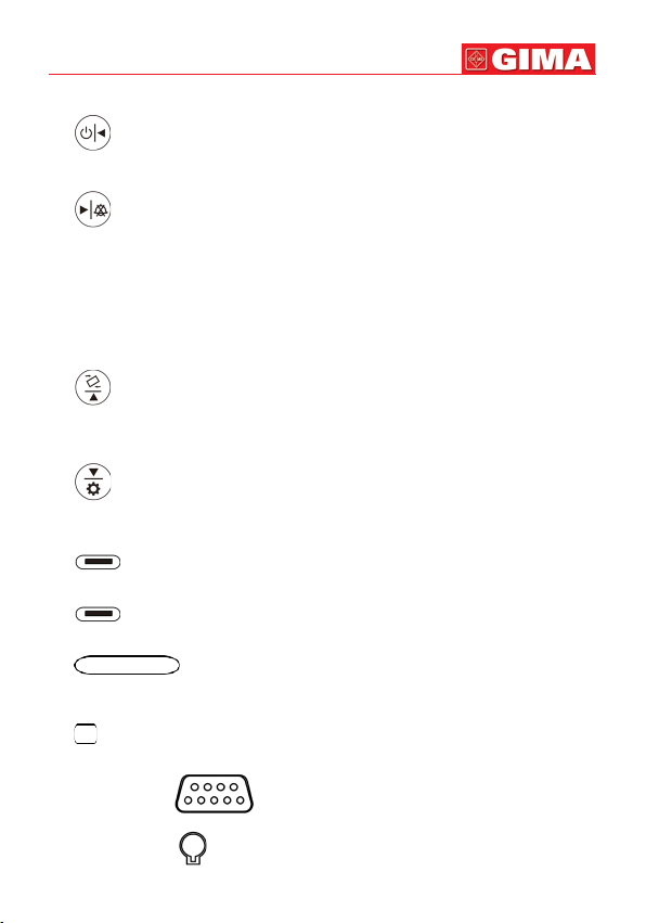
1. Display screen: Display measurement result, trends and menus.
2. (Power/Left): Power on/off the device by longtime pressing; On menu or
sub-menu screen, short time press it to move the cursor left or adjust the parameter values.
3. (Right/Sound): On data recall screen, longtime press this key, then the
delete dialog pops up; On measuring screen, longtime press it to disable or enable
the global sound.
On measuring screen, if the global sound is enabled, and alert event occurs, then
short time press it to perform audible alert reset (that’s to say, to alert sound will
be mute). When the current alert event ends or a new type of alert event occurs,
then status of audible alert reset will be ended (that’s to say, the alert sound will be
generated again when an alert event occurs). On menu or sub-menu screen, short
time press it to move the cursor right or adjust the parameter values.
4. (Auto-rotate/Up): On measuring screen, longtime pressing to enable or dis-
able the automatic screen orientation (on horizontal or vertical direction); On menu
or sub-menu screen, short time press it to move the cursor upwards or adjust the
parameter value.
5.
(Setting/Down): On measuring screen, longtime pressing to enter into set-
ting screen; On menu or sub-menu screen, short time press it to move the cursor
downwards or adjust the parameter value.
6. (Menu/Conrm): Short time press it to enter into menu screen, or to con-
rm the selection.
7. (Record/Back): Short time press it to enter into
or to back to the previous level of menu.
8. (Alert indicator): If the probe is not well placed or disconnected,
or the measured value exceeds the preset alert limit value, then the alert indicator
will ash with orange color.
9. (Power saving mode indicator) If the device is set as power saving mode,
then the indicator lights up. And on measuring screen, the indicator ashes with
the pulse beep.
10. Icon: “SpO2”: ( ):
SpO2 Probe Connector.
ENGLISH
SpO2 record list screen,
11. Icon: “TEMP”: ( ): Temperature Probe Connector.
Page 5

ENGLISH
12. ( ) USB connector. Used for data uploading or charging.
13. ( ): DC power input contact shoes with polarity indication. Used
for connecting external DC power input for charging the built-in rechargeable battery via the base.
42
1.2 Product Name and Model
Name: Handheld Pulse Oximeter
Model: SP-20
1.3 Structure
It consists of the main unit and
(Note: with optional temperature prob, this Oximeter can make temperature measurement.)
SpO2 probe.
1.4 Features
• It is lightweight, small in size and easy to carry.
• Color LCD to display plethysmogram and parameters.
• Measure
• PI (Perfusion Index) display is available.
• Up to 580 hours data storage for
• 16 user IDs for marking data and can be added.
• A built-on holder for convenient standing on desktop and display viewing.
• Real-time battery status display and low battery voltage indication.
• Auto power off is available.
• Audible and visual alert function is available.
• Data uploading to PC for management (Optional).
• Power saving mode is available.
SpO2, Pulse Rate and Temperature simultaneously.
SpO2 and PR and can be recalled.
1.5 Intended Use
This Handheld Pulse Oximeter is intended for measuring and recording the pulse rate,
functional oxygen saturation (
detecting
SpO2, pulse rate and temperature of adult and neonate patients in clinical
institutions and homes.
SpO2) and temperature (optional). It is applicable for
1.6 Working Environment
Operating temperature: 5~40°C
Operating humidity: 15%~93% (non-condensing)
Atmospheric pressure: 70kPa~106kPa
Page 6
43
ENGLISH
2 Power Supply
1. Internal power supply with built-in battery:
Built-in battery specication: 2000mAh lithium battery.
2. External power from the AC power adapter:
Use the AC power adapter provided by the manufacturer. Make sure the mains
power supply is 100-240VAC with 50/60Hz.
Note: it’s recommended to use the AC power adapter provided by the manufacturer.
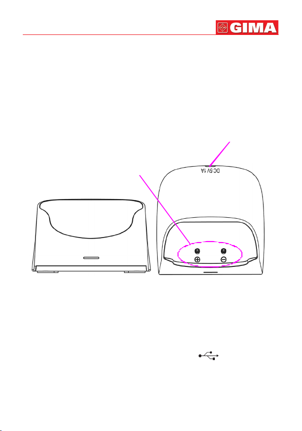
3. The Base:
Input: Micro USB connector, 5VDC/1A
Output: Contact pins. 5VDC/1A
Micro USB connector
Figure 2.1A Base--front view Figure 2.1B Base--top view
Description:
The base is used to hold the oximeter, and also for charging the oximeter. You can
charge the oximeter by the following methods:
1)
When the oximeter is held by the base, you can connect one end of the USB cable
to the USB connector on the back of the base marked with “DC 5V/1A”, and the
other end to the USB power source with output capacity of 5V DC/1A.
2) If the oximeter is not held by the base, then you can just connect one end of the USB
cable to the USB connector on the device marked with “ ”, and the other end
to the USB power source with output capacity of 5V DC/1A.
Notes:
1) During charging, if the oximeter is held by the base, please do not tilt the base
backwards too much, or the USB cable and the USB connector may be damaged.
2) Put the device into the base properly, and pay attention to the polarity markings, as
shown in gure 2.2.
Polarity markings
Page 7
Oximeter
Insert the oximeter
into the base by this
direction
Base
ENGLISH
44
Figure 2.2 Connection between oximeter and base
Page 8
45
ENGLISH
3 Make Measurement
3.1
SpO2 Measurement
Operation procedures:
1. Connect the
with “
the connector rmly and pull).
2. The red blinking light inside the clip of the
nection.
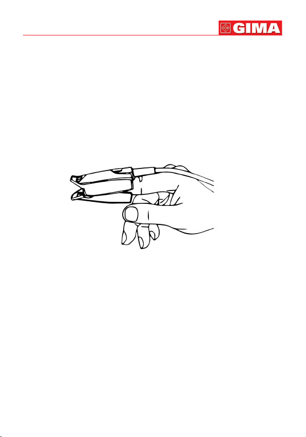
3. Insert one nger (index nger is preferred, the nail should be not too long) into the
clip of the probe according to the nger mark,as shown in gure 3.1.
4. The device will begin to take the measurement, and the measured result will be
displayed on the screen, as shown in gure 4.2.
Figure 3.1 demonstration for SpO2 probe
Safety instructions for SpO2 measurement
Long term use of the
pain, especially for those with microcirculatory problems. It is recommended that
the probe should NOT be applied to the same place for over two hours, change the
measurement site periodically and when necessary.
When the ambient temperature is over 35℃, please change the measuring site every
two hours; when the ambient temperature is over 37℃, please do NOT use the
sensor, as using in high temperatures can cause burns.
Do NOT place the
Do NOT put the
blood pressure measurement may affect the
The device is calibrated to display functional oxygen saturation
Do NOT allow the sensor cable to twist or bend.
Check the
sor.
When the temperature of the
SpO2 probe to the connector on the upper-side of the device marked
SpO2”. (Note: When disconnecting the connector, be sure to hold the head of
SpO2 probe indicates a successful con-
SpO2 probe on the same place may result in discomfort or
SpO2
SpO2 probe on a nger with edema or fragile tissue.
SpO2 probe and pressure cuff on the same limb, otherwise the
SpO2 sensor and cable before use. Do NOT use a damaged
SpO2 sensor is abnormal, do not use it further.
SpO2 measurement.
SpO2 sen-
Page 9
ENGLISH
46
Remove nail polish or other cosmetic products from the ngernail.
The ngernail should be of normal length.
The
SpO2 sensor cannot be immersed into water, liquid or cleanser.
The
SpO2 sensor can be repeatedly used. Please clean and disinfect before reuse.
Connector with the label “
SpO2” can only be connected with
SpO2 probe, and
connector with the label “TEMP” can only be connected with the temperature
probe.
3.2 Temperature Measurement (optional)
The infrared temperature probe is a delicate transducer. To operate please follow these
steps and procedures. Failure to accurately operate may cause damage to the probe.
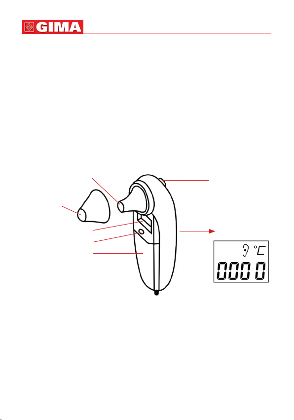
The infrared temperature probe is as shown in gure 3.2.
Please place the infrared temperature probe in a stable ambient temperature for 30
minutes before taking a measurement.
Measuring tip of
temperature probe
Temperature
Probe Cover
Measuring key
Small screen
Power on/off key
Battery cover
Big display screen
Figure 3.2 the infrared temperature probe
Operation procedure:
1. Connect the infrared temperature probe to the connector on the upper side of
device marked with “TEMP”.
2. When the screen shows as the big display screen in gure 3.2 and the temperature
unit “°C” is blinking, the user can begin to take the measurement.
3. Insert the tip of the temperature probe into the earhole and press the measuring key
to start the measurement. A short beep means the measurement has nished and
the result will be displayed on the big display screen on temperature probe and the
display screen of the Oximeter.
Page 10
47
Nota:
• If the temperature probe detects a hardware failure, the display screen on the infra-
red temperature probe will show “Err” and will not enter into measurement mode.
• The infrared temperature probe will switch to standby state automatically if there is
no operation for 1 minute. If a further measurement is needed, press the measuring
key and repeat step 2 and step 3.
• Normal body temperature varies depending on the position/area the measurement
is taken from. The following table shows the varying temperature ranges of the different body positions.
Temperature varying range at different body positions:
Arm 34,7 ~ 37,3°C
Oral 35,5 ~ 37,5°C
Rectal 36,6 ~ 38,0°C
Ear 35,8 ~ 38,0°C
Safety Instruction for Temperature Measurement
Do NOT take a measurement when the patient is moving.
Patients with tympanitis or otitis problems should NOT use this device.
When the infrared temperature probe is connected to the device, the probe will
consequently be at power-on status, therefore pressing the power on/off key on
the temperature probe will not cause any effect.
ENGLISH
4 Operation
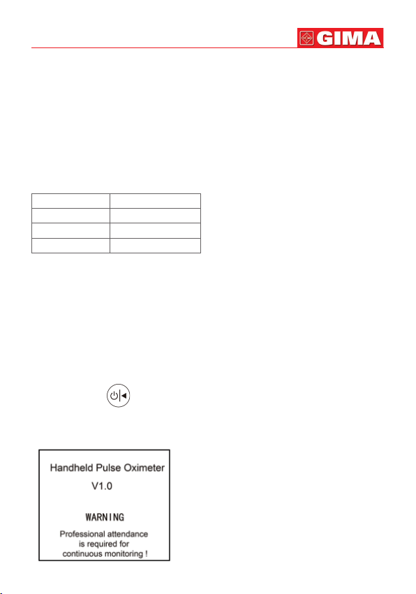
4.1 Power on/off the Oximeter
• Long pressing “ ” Power/Left key for 1~2 seconds, then the oximeter will be
powered on. The oximeter will do self-test and then the software version and warning message “Professional attendance is required for continuous monitoring!” will be
shown on the screen, as shown in gure 4.1 (refer to your oximeter for actual version).
Figura 4.1
Page 11
ENGLISH
48
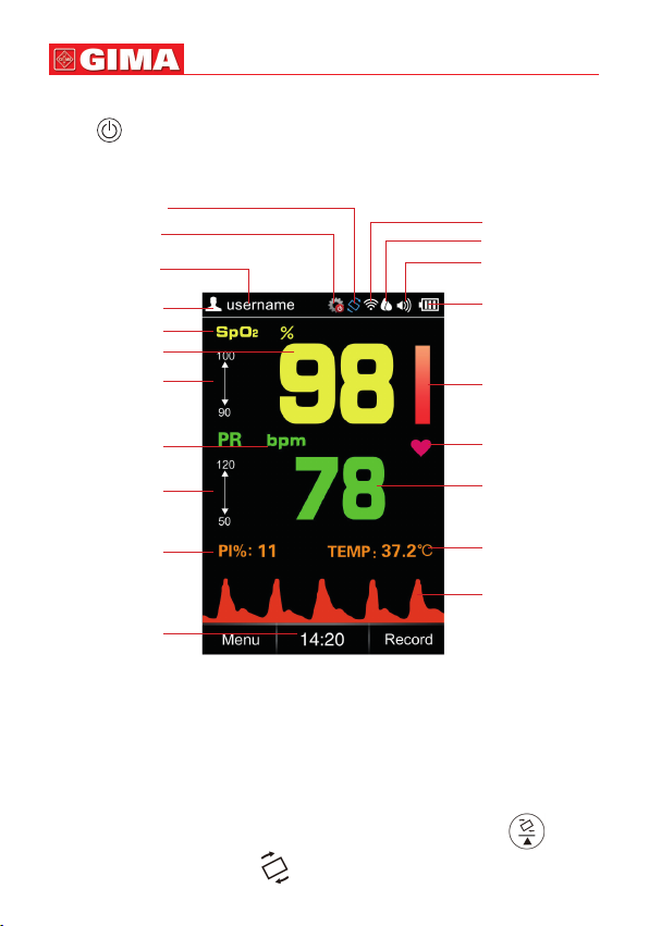
4.2 Default Display Screen
Press “ ” power key for 2 seconds to start up the Oximeter, then the screen will
display the default screen, as shown in Figure 4.2.
Auto-rotate icon
Auto power off
disable icon
User ID
Patient type
SpO2 mark
SpO2 value
SpO2 high/low
limit setting
value
Pulse rate
mark and unit
HR high/low limit
setting value
Perfusion index
Current time
Figure 4.2A Default Display Screen---in vertical
Wireless icon
Recording mode
Sound indicator
Battery indicator
Pulse Strength
bar-graph
Pulse symbol
Pulse rate value
TEMP value
Plethysmogram
Description:
• During measurement, if the nger is not inserted properly, or the probe is not con-
nected or the probe is off from the nger, then “Check Probe” message prompts and
keeps blinking on the screen, and “bibibi...” alert sound appears simultaneously.
Alert sound is sustaining for about 3 minutes, and if there is no any key operation in
this period, then the device will power off automatically (if the auto power off function is enabled).
• During measurement, longtime pressing Auto-rotate/Up key “ ”, then
the Auto-rotate white icon “ ” appears on the upper right corner of the
Page 12

49
ENGLISH
screen, it means the auto rotation function is enabled, if you place this oximeter horizontally, then the display shows in horizontal, as shown in gure 4.2B.
Figure 4.2B Default Display
Screen---in horizontal
•
Sound indicator “ ” means that the global sound is disabled, the user can enable
the global sound by longtime pressing “ ”. key. Longtime pressing “ ”
key again can disable the global sound, that’s to say, the speaker is turned off at all,
therefore, no pulse beep sound, no audible alert and no key click sound.
• If the global sound is enabled by longtime pressing “ ”, key, then during the
measurement, over-limit alert event or probe off event can activate the audible alert.
Refer to Section 6.2 for detailed alert indication sound.
• If the memory is full, the corresponding memory full icon appears on the screen:
“ ”, means temperature memory is full,“ ” means
memory is full; “ ”, means
SpO2 trend record memory is full. No display of the
SpO2 spot-check record
icon means the current corresponding storing space is not full. If the memory is full,
the data storing will continue in such way the new record will overwrite the oldest
record, so that it’s recommended to upload the stored data into the computer in
time.
4.3 Menu
On the default measuring screen, short time press “ ” Menu/Conrm key for
entering into main menu screen (as shown in Figure 4.3).
Page 13

ENGLISH
50
There are 9 functional icons in main
menu screen, press Up/Down/Left/
Right key can move the cursor to
make selection and press “
” Menu/Conrm key again to conrm
the selection.
• User ID: Add new or edit the current
User ID.
• User: Select patient type, “Adult”
and “Neonate” for option.
Note: when the device is set to the neonate patient type, then the User icon
“ ”
turns to grey
“ ”, and
the patient type on upper left corner
turns to pink “ ”.
• Recording mode: Select the data
recording mode, “Spot-check Record” and “Trend Record” for option.
• SpO2 record: Recall and review the
records stored on the oximeter, two
types of record for option: “Spotcheck Record” and “Trend Record”,
Figure 4.3 Main menu
see Section 4.4 for details.
• TEMP Record: Review the temper-
ature record list.
• Date: Set the time and date, see Section 4.3.6 for details.
• Settings: Set the system parameter, including brightness, sound volume, display
language, power saving mode etc., see Section 4.3.7 for details.
• Alerts: Set the low alert limit for
SpO2 and the high/low alert limit for PR, see Section
4.3.8 for details.
• Help: To view the tips information of
SpO2 measurement and temperature measure-
ment, see Section 4.3.9 for details.
4.3.1 User ID
On main menu screen, move the cursor on “User ID” and press Conrm key “ ”,
then the oximeter enters into User ID Setup screen, as shown in gure 4.4.
Page 14

51
ENGLISH
Figure 4.4A User ID setup screen
Move the cursor on “Edit” and press Conrm
key “ ”; when the cursor turns to blue,
then the user can edit the User ID, and move
the cursor on “OK” to conrm the edit, the edit
screen is as shown in gure 4.4B.
Figure 4.4B User ID edit screen
4.3.2 User
On main menu screen, move the cursor on “User” and press Conrm key “ ”,
then the oximeter enters into Patient type Setup screen, as shown in gure 4.5.
Figure 4.5 Patient type setup screen
Page 15

52
4.3.3 Recording Mode
On main menu screen, move the cursor on
“Recording Mode” and press Conrm key
“ ”, then the oximeter enters into Recording Mode Setup screen, as shown in gure
4.6.
Figure 4.6 Recording mode setup screen
Note: When selecting “Spot-check Record” for data recording, the measuring time
should last over 10 seconds to get one spot-check reading, or no reading value will
not be recorded in Spot-check data record; When selecting “Trend Record”, the
measuring time should exceed 30 seconds, or no one record will be recorded in Trend
data record list.
4.3.4 SpO2 Record
On main menu screen, move the cursor on “
“ ”, then the oximeter enters into
SpO2 Record” and press Conrm key
SpO2 record review method selecting screen,
as shown in gure 4.7.
Figure 4.7 SpO2 record review method selecting screen
Refer to Section 4.4 for details.
4.3.5 TEMP Record
On main menu screen, move the cursor on “TEMP Record” and press Conrm key
“ ”, then the oximeter enters into temperature record list screen, as shown in
gure 4.8.
Page 16

53
Figure 4.8 TEMP record list screen
4.3.6 Date
On main menu screen, move the cursor on
“Date” and press Conrm key “ ”, then
the oximeter enters into date setup screen, as
shown in gure 4.9.
Figure 4.9 Date setup screen
Date setting procedure:
1) Move the cursor stays on the Year of the date, press Conrm key “ ” to active
Year option, the cursor ashes on the Year of the date.
2) Press Up/Down key to adjust Year.
3) Press “ ” (Conrm) key to conrm and exit from date setting.
4) The procedures of adjusting Month, Day, Hour, Minute and Second value are the
same with Year adjustment.
Date Format: DD-YY-MM; Time Format: HH:MM:SS
Page 17

ENGLISH
54
Note: The setting operations of other parameters (such as User ID, User, Auto Power
Off, Power Saving etc.) are the same with date setting.
4.3.7 Settings
On main menu screen, move the cursor on “Settings” and press Conrm key “ ”,
then the oximeter enters into system setting screen, as shown in gure 4.10.
Figura 4.10
System
setting screen
Description:
• Brightness: To set the brightness of backlight, 6 levels for optional, the factory
default is level 3, as shown in gure 4.10A.
• Volume: To set the sound volume (including alert sound, pulse beep sound and key
click sound), 6 levels sound volume for optional, the factory default is level 3, as
shown in gure 4.10B.
• Pulse beep: To turn on/off pulse beep, the factory default is “On”, as shown in gure
4.10C. If the global sound is enables by longtime pressing , key, and the pulse
beep is set to “On” option, and when there is no over-limit event, then pulse beep
sound can be heard during
SpO2 measurement.
• Language: This oximeter provides the display with two languages: English and Sim-
plied Chinese, the factory default is “English”, as shown in gure 4.10D.
• Auto power off: To turn on/off the Auto Power Off mode, the factory default is “On”,
as shown in gure 4.10E.
• Wireless: To turn on/off the wireless connection function, the factory default is “On”,
as shown in gure 4.10F.
• Power saving mode: To turn on/off the Power Saving mode, the factory default is
“On”, as shown in gure 4.10G.
• TEMP unit: To set the temperature unit, “°C (Celsius)” and “°F (Fahrenheit)” for
Page 18

55
ENGLISH
option, the factory default is “°F”, as shown in gure 4.10H.
• Factory Default: Enter into the factory default setting, as shown in gure 4.10I.
• Version: For viewing version number of the software, as shown in gure 4.10J.
• Demo: Enter into the Demonstration mode, as shown in gure 4.10K.
Figure 4.10A Brightness setup Figure 4.10B Volume setup
Figure 4.10C Pulse beep setup Figure 4.10D Language setup
Figure 4.10E Auto Power OFF setup Figure 4.10F Wireless setup
Figure 4.10G Power Saving setup Figure 4.10I TEMP unit setup
Page 19

ENGLISH
Figure 4.10H Version info Figure 4.10J Default setting
Notes:
• When the Auto Power Off is set to “On” option, if there is no key operation for 3 minutes,
then the oximeter will power off automatically.
• When the Power Saving Mode is set to “On”
option, during the measurement, if there is no
key operation for 1 minute, the screen display will be dim for power saving. The display
brightness will resume to normal condition by
pressing any key.
Figura 4.10K Modalità Demo
56
4.3.8 Alerts
On main menu screen, move the cursor on “Alerts”
and press Conrm key “ ”, then the oximeter enters into alerts setting screen, as shown in
gure 4.11.
Figure 4.11 Alerts setting screen
Page 20

57
ENGLISH
• SpO2 Lo-Limit:
SpO2 low limit setting; range: 50%~99%, the step is 1%. The fac-
tory default value for adult is 90% and 95% for Neonate.
• PR Hi-Limit: High limit setting of pulse rate; range: 100~240bpm. From 100 to 150,
the step is 1bpm, and from 150 to 240, the step is 5bpm. The factory default value
for adult is 120bpm and 160bpm for neonate.
• PR Lo-Limit: Low limit setting of pulse rate; range: 30~99bpm, and the step is
1bpm. The factory default value for adult is 50bpm and 60bpm for neonate.
Note: When the
SpO2 reading is lower than or equal to the preset alert setting or the
PR reading is higher than or equal to the preset high limit or the PR reading is lower
than or equal to the preset low limit, then the over-limit alert event will be activated,
that’s, the alert sound “bibibibi...” occurs, and the corresponding reading(s) blinks.
When measured on neonate, if the
SpO2 reading is lower than or equal to the preset
alert setting for 10 seconds, then the alert sound and blinking display will be activated.
4.3.9 Help
On main menu screen, move the cursor on “Help” and press Conrm key “ ”,
then the oximeter help information screen, which shows
SpO2 and temperature meas-
urement tips, as shown in gure 4.12.
Help
Baby L
Infant Pediatric
Note: Make sure the light
emitting and receiving ends
are aimed at each other. V
1/2
Help
Note: Remove temperature probe
cover, insert the probe into earhole,
then press key to start measurement.
2/2
Figure 4.12 Help information Figure 4.12 Help information
---SpO2 measurement ---TEMP measurement
Page 21

ENGLISH
4.4 Record
4.4.1 Data Recall
On main default screen, short time press
Record/Back key “ ” to enter into
data recall screen, as shown in gure 4.13.
Figure 4.13 SpO2 record
SpO2 records include two types, Spot-check and Trend Record, Spot-check Record is a list showing the recording time,
spot-checking event, as shown in gure 4.14
The corresponding
User ID for the
selected record
SpO2 value and pulse rate value for each
User and
58
Figure 4.14 Spot-check Record list
If Trend Record is selected, then the screen shows a list of trend data record, and
each record corresponds to a period of recording at a xed time interval (1 second),
as shown in gure 4.15, press Up/Down key ( / ) to select one record you
need to review.
Select one record you need to review, and press Conrm key “ ”, then the
screen shows the corresponding User, User ID, and trend graph, as shown in gure
4.16.
Page 22

59
The corresponding
User and
User ID for the
selected record
Figure 4.15 Trend record---List
The corresponding
User and
User ID for the
selected record
SpO
2
trend graph
ENGLISH
Recording
time
PR trend graph
Figure 4.16 Trend record---Trend graph
Page 23

ENGLISH
60
4.4.2 Data Deletion
On the record list screen shown in gure 4.14 or 4.15, move the cursor on the record
you want to delete, and longtime pressing Sound/Right key (“ ”), then an message “Are you sure to delete all?” prompts on the screen, as shown in gure 4.16.
Figure 4.16 Delete records
At this time, short time press Menu/Conrm (“ ”) key to conrm and delete
the records. Or short time press Record/Back (“ ”) key to return to record list
screen.
4.4.3 Data Upload
If you want to upload the stored data (
SpO2, PR and TEMP values) to the computer,
then Make sure the provided USB data cable is well connected between the device
and PC before uploading data, as shown in gure 4.17. Refer to the instruction in
“Oximeter Data Manager User Manual”for detailed operation.
Figure 417 Data uploading screen
• During data uploading, the user can not do any operation on the oximeter.
When the wireless transmission function is on, the Handheld Pulse Oximeter can communicate with a host (such as computer or mobile) for viewing and management.
a. Open the host’s wireless function and procedure and start to scan the SP-20 Oxi-
meter.
b. The host will pair with the SP-20 Oximeter at a moment.
c. After connecting, the host can display and manage the measurement data of SP-20
by wireless
Page 24

61
ENGLISH
The pairing and transmitting distance of wireless function is 8 meters in the normal.
If the host can’t pair with the SP-20, you will try to narrow the distance between the
host and SP-20.
The SP-20 can pair and transmit with the host under the wireless coexistence environment, but other wireless device may still interface with pairing and transmission
between the host and the SP-20 device under uncertain environment. If the host and
the SP-20 display inconsistent, you may need to change the environment.
4.4.4 Data Management
The user can go to our website to download the corresponding PC Software “Oximeter Data Manager” for this oximeter with the link: http://www.creative-sz.com/
downloads
With the computer installed this PC software, you can upload the data stored in the
oximeter to your PC via wireless or data cable . It’s convenient for user to review the
data records and statistical result, aa well as archive patients’ data.
5 Technical Specications
A. Display Panel: 3.5 inch color TFT LCD;
B. Power Supply:
Internal power supply: 2000mAh lithium battery
AC power adapter: 5VDC/1A,
Working current: ≤180mA
Input power for AC power adapter: <15VA
The typical continuous operation time of the battery: 18 hours (when screen display
is automatically off and wireless function is disabled).
The typical service life of the battery: 5 years.
C. SpO2 Measurement
Transducer: dual-wavelength LED sensor with wavelength:
Red light: 663 nm, Infrared light: 890 nm.
Maximal average optical output power: ≤ 2mW
Display range: 0~100%
Measuring accuracy: A
for
SpO2 range from 70% to 100%.
SpO2 low alert limit setting range: 50%~99%
The device is calibrated to display functional oxygen saturation.
The functional tester cannot be used to assess the accuracy of the
the device.
D. Pulse Rate Measurement
Display and measuring range: 30bpm~250bpm
Accuracy: ±2bpm or ±2% (whichever is greater)
E. Perfusion Index Display
Range: 0.2%~20%
value (dened in ISO 80601-2-61) is not greater than 2%
RMS
SpO2 probe or
Page 25

ENGLISH
62
F. Temperature Measurement
Measuring range: 32.0°C~43.0°C
Measuring accuracy: ±0.2°C for temperature range from 35.0°C to 42.0°C, and
±0.3°C for the rest.
Response time: ≤5s
Patient Group: Adult and Neonate
Measuring site: earhole
Deviation: ≤0.1°C
G. Operating Environment
Operating Temperature: 5°C ~40°C
Operating Humidity: 15%~93%
Atmospheric pressure: 70kPa~106kPa
Note: portable and mobile RF communications equipment may affect the perfor-
mance of the Oximeter.
H. Low Perfusion Performance
The accuracy of
SpO2 and PR measurement still meet the precision described
above when the modulation amplitude is as low as 0.4%.
I. Resistance to interference of surrounding light:
The difference between the
SpO2 value measured in the condition of indoor natural
light and that of darkroom is less than ±1%.
J. Wireless (bluetooth) function
Frequency band: 2.4GHz
Working prole: BLE V4.0
K. Dimensions: 158 mm (L) × 73 mm (W) × 25 mm (H)
Net Weight: about 230g (including battery)
L. Classication
Type of protection against electric shock:
Internally powered equipment and Class II.
Degree of protection:
Type BF applied parts.
Degree of protection against harmful ingress of liquids: The equipment is IP22
with protection against harmful solid foreign objects and ingress of liquid.
Mode of operation: Continuous operation.
Electro-Magnetic Compatibility: Group I, Class B
M. Data update period
The update time for determining
SpO2 and PR value is 8 seconds, and the display-
ing update time is 1 second.
Remark: The oximeter calculates the
SpO2 and PR value, every second by use of
recently acquired data segment, then yields the displaying value by moving average of the latest calculated parameters. The reading value of
SpO2 and PR on the
oximeter is updated every second, and the displayed plethysmogram is a normalized waveform. If the signal is no integral (such as with too much noise, or poor
signal to noise ratio or signal is lost), then the
SpO2 and PR will be identied as an
invalid value, that’s to say, the numeric reading will disappear and be displayed as
“--” instead.
Page 26

63
Note: The oximeter is calibrated in the factory before sale, and there is no need for
user to calibrate again.
ENGLISH
6 Over-limit Indication
6.1 Limit settings
•
SpO2 low limit setting range: 50% ~ 99%.
• Pulse Rate limits setting range:
High: 100bpm--240bpm
Low: 30bpm--99bpm
During the measurement, if the measured value exceeds the preset value, the alert
beeping sound will be activated, the value that is over-limit will blink at the same time.
6.2
Over-limit indication sound mute setting
• During the measurement, if the global sound is enables, then short time press “ ”
key to perform audible alert reset (that’s to say, the alert sound will be mute, and icon
“ ” appears on the upper right corner of the screen), but the over-limited value
still keeps blinking. when the current alert event ends or a new type of alert event
occurs, then the status of audible alert reset will be ended (that’s to say, the alert
sound can be generated when an alert event occurs, and icon “ ” appears on the
upper right corner of the screen).
• When the global sound is enables, then the longtime pressing “ ” key cam
disable the global sound, and the sound icon becomes “ ”. Longtime pressing
“ ” key again can enable the global sound.
Note: “ ” means the speaker volume is set as 1 or 2 grid(s); “ ” means the
speaker volume is set as 3 or 4 grids; “ ” means the speaker volume is set as 5
or 6 grids.
• During the measurement, if the probe is off or disconnected, the message “Check
Probe” shows and keeps blinking on the display screen. The alert sound starts (interval is 5 seconds). If the probe is still off and lasts for about 3 minutes, then the
Oximeter will power off automatically.
7 Packing List
1. An Oximeter
2. A
SpO2 probe
3. User Manual
4. A oximeter rubber cover
5. A charging base
Page 27

ENGLISH
6. A temperature probe (optional)
7. Charging cable (optional)
8. A USB data cable (optional)
Notes:
1. The accessories are subject to change. See the package in your hand for
detailed items and quantity.
2. All the parts of the device should NOT be replaced at will. If necessary,
please use the components provided by the manufacture or those that are
of the same model and standards as the accessories along with the device
which are provided by the same factory. Otherwise, negative effects concerning safety and biocompatibility etc. may be caused.
3. This device can only connect with the manufacture nominated device.
64
8 Repair and Maintenance
8.1 Maintenance
The expected service life(not a warranty) of this device is 5 years. In order to ensure its
long service life, please pay attention to the maintenance;
•
If the battery is damaged, please contact your local sales representative or the manufacture.
•
Please store the device carefully to avoid being damaged by pets, pests or children.
•
The recommended storage environment of the device:
Ambient temperature: -20ºC ~60ºC
Relative humidity: 10%~95%
Atmospheric pressure: 50kPa~107.4kPa
Storage and Transportation between uses:
– 25°C without relative humidity control;
and + 70°C at a relative humidity up to 93% (non-condensing).
•
The oximeter is calibrated in the factory before sale, there is no need to calibrate it
during its life cycle.
However, if it is necessary to verify its accuracy routinely, the user can do the verica-
tion by means of
SpO2 simulator, or it can be done by the local third party test house.
8.2 Cleaning and Disinfecting Instruction
• Surface-clean sensor with a soft cloth by wetting with a solution such as 75% iso-
propyl alcohol, if low-level disinfection is required, use a 1:10 bleach solution.
• Then surface-clean by a dampened cloth and let it air dry or wipe it with a cloth.
• Please clean and disinfect the device after using to avoid cross infection.
High-pressure disinfection cannot be used on the device.
Do not immerse the device in liquid
Page 28

65
ENGLISH
9 Troubleshooting
Trouble Possible Reason Solution
Unstable SpO2
and Pulse Rate
display
Unable
to measure
Temperature
Device will not
switch on
No Display 1. The device will power off
No Signal 1. Probe off or incorrect
1. The nger is not placed
far enough inside.
2. The nger is shaking
or the patient is moving.
1. Temperature probe
is not connected properly
1. The batteries are drained
or almost drained.
2. The device is
malfunctioning.
automatically when there is
no signal and no operation
for 1 minute.
2. The battery voltage is low.
connection.
2. Incorrect nger insert
3. Probe is damaged.
1. Place the nger
correctly inside and try
again.
2. Reduce patient
movement.
2. Reinsert the probe into
the device
1. Recharge battery.
2. Please contact the local
service center.
1. Normal.
2. Recharge battery.
1. Reconnect the probe.
2. Reinsert the nger.
3. Replace a new probe.
Page 29

ENGLISH
66
10 Frequently Asked Questions
1. Q: What’s SpO2?
A:
SpO2 means the saturation percentage of oxygen in the blood.
2. Q: What’s the normal range of SpO2 value for healthy people?
A: The normal range varies by individual, but usually over 95%, otherwise, please
consult your physician.
3. Q: What’s the normal range of PR value for healthy people?
A: Usually, the normal range is 60bpm~100bpm.
5. Q: Why do the display value of SpO2 and PR vary with time?
A: The measured
of patient’s physiological conditions.
5. Q: What to do if there is no SpO2 and PR reading?
A: Do not shake the nger, and keep calm during the measurement. Please also
avoid the oximeter and the cuff on the same limb for blood pressure and oxygen
saturation measurement simultaneously.
6. Q: How to conrm that the SpO2 reading is true or accurate?
A: Hold breath for a while (50 seconds or more), if the
decreases, it means that the
change.
7. Q: When to charge the batteries?
A: The icon of low battery will appear on the screen when the battery voltages are
low. By then, device need to be charged.
8. Q: What factors will affect the SpO2 accuracy?
A: a) Intravascular dyes such as indocyanine green or methylene blue;
b) Exposure to excessive illumination, such as surgical lamps, bilirubin lamps, u-
orescent lights, infrared heating lamps, or direct sunlight;
c) Vascular dyes or external used color-up product such as nail enamel or color
skin care;
d) Excessive patient movement;
e) Placement of a sensor on an extremity with a blood pressure cuff, arterial cath-
eter, or intravascular line;
f) Exposure to the chamber with High pressure oxygen;
g) There is an arterial occlusion proximal to the sensor;
h) Blood vessel contraction caused by peripheral vessel hyperkinesias or body
temperature decreasing;
i) Low perfusion condition (Perfusion Index is small).
SpO2 and PR value changes in correspondence with the change
SpO2 value signicantly
SpO2 reading truly reects the physiological condition
Please contact the local distributor or manufacturer if necessary.
Page 30

67
Appendix
I. Key of Symbols
Symbols on the screen
Symbol Description
%SpO2 The oxygen saturation
PI% Perfusion Index
bpm
Pulse rate (Unit: beats per minute)
Pulse bar graph
Low battery voltage
Battery is full
Alert reset icon
Speaker mute icon
Speaker volume icon
SpO2 spot-check record memory full
SpO2 trend record memory full
ENGLISH
Temperature memory full
Wireless transmission icon
(Neonate/Adult) Patient type
Page 31

ENGLISH
Symbols on the panels
Symbol Description Symbol Description
SpO2SpO2 probe connector
TEMP
Temperature probe
connector
Power/Left Key Product code
Right/ Sound Key Lot number
Caution: read instructions
(warnings) carefully
Keep in a cool, dry place
68
Auto-rotate/Up Key
Setting/Down Key Date of manufacture
Menu/Conrm key
or Record/Back key
Serial number Type BF applied part
Medical Device complies
with Directive 93/42/EEC
Authorized representative in the European
community
WEEE disposal No alarm
Keep away from sunlight
Manufacturer
Follow instructions for use
Do not litter at will
Page 32

69
ENGLISH
II. Common Knowledge
1 Meaning of SpO
SpO
is the saturation percentage of oxygen in the blood, so called O2 concentration
2
in the blood; it is dened by the percentage of oxyhemoglobin (
hemoglobin of the arterial blood.
reect the respiration function; it is calculated by the following method:
SpO2 = HbO2 / (HbO2 +Hb)×100%
Hb
O2 are the oxyhemoglobins (oxygenized hemoglobin), Hb are those hemoglobins
which release oxygen.
2 Principle of Measurement
Based on Lamber-Beer law, the light absorbance of a given substance is directly proportional with its density or concentration. When the light with certain wavelength
emits on human tissue, the measured intensity of light after absorption, reecting and
attenuation in tissue can reect the structure character of the tissue by which the light
passes. Due to that oxygenated hemoglobin (HbO2) and deoxygenated hemoglobin
(Hb) have different absorption character in the spectrum range from red to infrared
light (600nm~1000nm wavelength), by using these characteristics,
termined.
percentage of the hemoglobin that can transport oxygen. In contrast, hemoximeters
report fractional oxygen saturation – a percentage of all measured hemoglobin, including dysfunctional hemoglobin, such as carboxyhemoglobin or metahemoglobin.
Clinical application of pulse oximeters:
to reect the respiration and ventilation function, so
cal becomes more popularly, such as monitoring the patient with serious respiratory
disease, the patient under anesthesia during operation, premature and neonate. The
status of
patient earlier, thereby preventing or reducing accidental death caused by hypoxia
effectively.
3 Normal SpO2 Range and Default Low Limit
In campagna area, healthy people’s
ues below 94% are determined as hypoxia.
threshold for determining anoxia by most researchers, so
ter is set as 90% generally.
4 Factors affecting SpO2 accuracy (interference reason)
• Intravascular dyes such as indocyanine green or methylene blue.
• Exposure to excessive illumination, such as surgical lamps, bilirubin lamps, uorescent lights, infrared heating lamps, or direct sunlight.
• Vascular dyes or external used color-up product such as nail enamel or color skin
care.
2
Hb
O
) in the total
SpO
is an important physiological parameter to
2
2
SpO2 can be de-
SpO2 measured by this oximeter is the functional oxygen saturation -- a
SpO2 is an important physiological parameter
SpO2 monitoring used in clini-
SpO2 can be determined in time by measurement and nd the hypoxemia
SpO
value is greater than 94%, so the val-
2
SpO2 <90% is considered as the default
SpO2 low limit of the oxime-
Page 33

ENGLISH
70
• Excessive patient movement.
• Placement of a sensor on an extremity with a blood pressure cuff, arterial catheter,
or intravascular line.
• Exposure to the chamber with High pressure oxygen.
• There is an arterial occlusion proximal to the sensor.
• Blood vessel contraction caused by peripheral vessel hyperkinesias or body temperature decreasing.
5 Factors causing low SpO2 value (pathology reason)
• Hypoxemia disease, functional lack of HbO2.
• Pigmentation or abnormal oxyhemoglobin level.
• Abnormal oxyhemoglobin variation.
• Methemoglobin disease.
• Sulfhemoglobinemia or arterial occlusion exists near sensor.
• Obvious venous pulsations.
• Peripheral arterial pulsation becomes weak.
• Peripheral blood supply is not enough.
Disposal: The product must not be disposed of along with other domestic waste. The
users must dispose of this equipment by bringing it to a specic recycling point for electric
and electronic equipment.
For further information on recycling points contact the local authorities, the local recycling
center or the shop where the product was purchased. If the equipment is not disposed
of correctly, nes or penalties may be applied in accordance with the national legislation
and regulations.
GIMA WARRANTY CONDITIONS
Congratulations for purchasing a GIMA product.
This product meets high qualitative standards both as regards the material and the production.
The warranty is valid for 12 months from the date of supply of GIMA.
During the period of validity of the warranty, GIMA will repair and/or replace free of charge all
the defected parts due to production reasons. Labor costs and personnel traveling expenses
and packaging not included. All components subject to wear are not included in the warranty.
The repair or replacement performed during the warranty period shall not extend the warranty.
The warranty is void in the following cases: repairs performed by unauthorized personnel or with
non-original spare parts, defects caused by negligence or incorrect use.
GIMA cannot be held responsible for malfunctioning on electronic devices or software due to
outside agents such as: voltage changes, electro-magnetic elds, radio interferences, etc.
The warranty is void if the above regulations are not observed and if the serial code (if available)
has been removed, cancelled or changed. The defected products must be returned only to the
dealer the product was purchased from. Products sent to GIMA will be rejected.
Page 34

71
FRANÇAIS
Cher client,
Merci pour avoir acheté ce produit de qualité. Veuillez lire attentivement le mode d’emploi avant d’utiliser l’appareil. Le non respect de ces instructions peut causer des
anomalies dans les résultats de la mesure ou endommager l’oxymètre.
Il est interdit de photocopier, reproduire ou traduire ce document sans l’accord écrit
préalable du fabricant. Nous nous réservons le droit de mettre à jour ou de modier ce
mode d’emploi à tout moment sans préavis.
Version du mode d’emploi : Ver 1.5
Date de publication : Le 8 mai, 2019
Tous droits réservés
Remarques :
• Les informations contenues dans ce mode d’emploi pourront être modiées sans
préavis.
• Les informations fournies par Creative sont considérées comme étant précises et
ables. Toutefois, Creative n’assume aucune responsabilité quant à leurs utilisations, aux problèmes de violation de brevets ou d’autres droits de tiers qui seraient
la conséquence de leur utilisation.
Instructions pour une utilisation en toute sécurité
Contrôlez l’appareil pour vous assurer de l’absence de dommages visibles qui pourraient compromettre la sécurité de l’utilisateur et les résultats des mesures. Il est recommandé de contrôler l’appareil au moins avant chaque utilisation. En cas de dommage évident, cessez immédiatement d’utiliser l’appareil.
Les opérations d’entretien et de réparation ne doivent être effectuées que par des
techniciens qualifiés. Les utilisateurs ne sont pas autorisés à effectuer ces opérations
par eux-mêmes.
L’oxymètre ne doit être utilisé qu’avec les équipements et accessoires spécifiés dans
le Mode d’emploi.
Mises en garde
Risques d’explosion — NE PAS utiliser l’oxymètre dans un environnement conte-
nant des gaz inammables, tels que certains produits anesthésiants inammables.
N’utiisez PAS l’oxymètre sur le patient pendant une procédure d’IRM ou de CT. Cet
appareil N’EST PAS compatible avec les procédures IRM.
Mises en garde
Une gêne ou une douleur peuvent apparaitre si le capteur de l’appareil est appliqué
au même endroit pendant longtemps, en particulier chez les patients souffrant d’une
mauvaise microcirculation. Veuillez ne pas appliquer l’oxymètre au même endroit
plus de 2 heures de suite et de réduire le temps d’application en cas de conditions
anormales. Contrôlez et repositionnez fréquemment le capteur de l’oxymètre.
Une mauvaise application du capteur
SpO2, créant une pression excessive pen-
dant une période prolongée, peut causer des blessures.
Page 35

FRANÇAIS
72
Le fait de serrer trop le doigt avec le capteur
SpO2 peut provoquer des pulsations
veineuses et gêner la circulation du sang, risquant ainsi de créer un œdème interstitiel, des phénomènes d’hypoxie et d’obtenir des mesures inexactes.
Des tests de biocompatibilité ont été effectués sur toutes les parties appliquées,
mais certains patients particulièrement allergiques pourraient quand-même faire un
choc anaphylactique. N’utilisez pas cet appareil chez ces patients.
Dans le cas de certains patients, l’évaluation de l’endroit où placer le capteur doit
être effectuée de façon particulièrement soigneuse. Le capteur ne peut pas être
appliqué sur un œdème ou sur une partie sensible.
Respecter la réglementation locale lors de l’élimination de l’appareil et de ses ac-
cessoires, une fois leur durée de vie utile terminée.
NE faites PAS faire fonctionner l’appareil dans des environnements où sont pré-
sentes de fortes interférences électromagnétiques produites par exemple par des
appareils de radiologie, des télévisions, des talkie-walkies, etc.
FaItes attention au câble du capteur
SpO2 lorsque vous utilisez l’oxymètre, an
d’éviter qu’il ne serre le cou du patient.
Remarques
Protéger l’oxymètre en le tenant éloigné de la poussière, des vibrations, des subs-
tances corrosives, des substances explosives, des températures élevées et de
l’humidité.
Si l’oxymètre devait être mouillé, cessez de l’utiliser jusqu’à ce qu’il soit sec.
Contrôlez qu’il fonctionne encore correctement avant de recommencer à l’utiliser.
Lorsque l’appareil est déplacé d’un lieu froid à un lieu chaud et humide, ne l’utilisez
pas immédiatement. Attendez au moins 15 minutes pour que la température de
l’oxymètre atteigne la température ambiante.
N’appuyez PAS sur les boutons placés sous l’écran avec des outils coupants ou
pointus.
NE stérilisez PAS l’oxymètre et les capteurs avec de la vapeur à haute pression
ou avec des procédures de stérilisation à haute température. Faites référence au
chapitre de ce Mode d’emploi relatif au nettoyage et à la désinfection.
Cet appareil n’est pas prévu pour une utilisation thérapeutique.
L’équipement a un degré de protection IP22 contre l’intrusion de corps solides et
liquides. Cela signie qu’il est protégé contre l’intrusion de corps solides supérieurs
à 12,5 mm et contre les chutes de gouttes d’eau jusqu’à 15° de la verticale.
Faites attention aux effets des bres textiles, de la poussière, de la lumière (lumière
solaire comprise), etc.
Déclaration de conformité
Le fabricant déclare que cet appareil est conforme aux normes suivantes :
CEI 60601-1:2005+A1 : 2012, CEI60601-1-2: 2014, CEI60601-1-11: 2010, ISO 806012-61:2011 et suit les dispositions de la directive du conseil MDD93/42/CEE.
 Loading...