

Page 1

Gima S.p.A.
Via Marconi, 1 - 20060 Gessate (MI) Italy
gima@gimaitaly.com - export@gimaitaly.com
PROFESSIONAL MEDICAL PRODUCTS
www.gimaitaly.com
PULSOXIMETRO VETERINARIO OXY-100
OXY-100 VET PULSE OXIMETER
Manuale d’uso - User manual
ATTENZIONE: Gli operatori devono leggere e capire
completamente questo manuale prima di utilizzare il prodotto.
ATTENTION: The operators must carefully read and completely
understand the present manual before using the product.
34343
Shenzhen Creative Industry Co., Ltd.
Floor 5, BLD 9, BaiWangxin HighTech Industrial Park,
Songbai Road, Xili Street, Nanshan District,
518110 Shenzhen, P.R. China
Made in China
Shanghai International Holding Corp. GmbH (Europe)
Eiffestrasse 80, 20537 Hamburg, Germany
M34343-M-Rev.2-11.19
0123
Page 2

ENGLISH
16
Instructions for Safe Operations
• Check the device to make sure that there is no visible damage that may affect user’s safety and
measurement performance. When there is obvious damage, stop using the device.
• Necessary service must be performed only by qualied technicians. Users are not permitted to
repair it by themselves.
• The oximeter cannot be used together with the devices not specied in User Manual.
Cautions
• Explosive hazard-DO NOT use the oximeter in environment with inammable gas such as some
ignitable anesthetic agents.
• DO NOT use the oximeter while the testee is under MRI or CT scanning.
Warnings
• An uncomfortable or painful feeling may appear if using the sensor of this device continuously on the
same place for a long time, especially for the testee with poor microcirculation. It is recommended
that the sensor should not be applied to the same location for longer than 2 hours. If any abnormal
condition is found, please change the position of sensor.
• For the individual testee, there should be a more prudent inspecting in the placing process. The
sensor can not be clipped on the edema and tender tissue.
• The local law should be followed when disposing of the expired device or its accessories.
Attentions
• Keep the oximeter away from dust, vibration, corrosive substances, explosive materials, high
temperature and moisture.
• If the oximeter gets wet, please stop operating it. When it is carried from a cold environment to a
warm and humid environment, please do not use it immediately.
• DO NOT operate the button on the front panel with sharp materials.
• High temperature or high pressure steam disinfection to the oximeter or sensors is not permitted.
Refer to related chapter for instructions of cleaning and disinfection.
• The intended use of this device is not for therapy purpose.
• Caution: U.S. federal law restricts this device to sale or use by or on the order of a physician.
1 Overview
1.1 Appearance
Figure 1
Display screen
Navigation keys
Reserved portData interface
Power/Back
Recall/MuteMode/OK
SpO2 probe connector
Page 3

17
1. Display screen: display SpO2 plethysmogram and parameter values.
2. Navigation key:
ENGLISH
: Up/Left/Increase
Press this key, the default screen can be shifted to display pulse rate (PR) or perfusion index (PI). If on
the system setup screen, press it to move the cursor upwards or to the left and adjust parameter values.
: Down/Right/Decrease
Its function is similar with the key “: Up/Left/Increase”.
3. (Mode/OK): press this key, the screen can be shifted between default screen and other screen
layout; longtime press it, the menu screen will be displayed; when you nish parameter setting, press
this key to conrm.
4. (Data interface): used for uploading data (Optional function).
5. (Reserved port): for future use.
6. (Power/Back): Power on/off the device by longtime pressing; short time press it to back to upper
level operation.
7. “ ” (Recall/Alarm mute): Longtime press it to enter SpO2 recall screen; when the device is alarming,
short time pressing will mute the alarm sound, the mute state will persist for about 90s. If the alarm event
still exist after this mute period (90s), then the alarm sound will resume.
8. Icon: “SpO2”: SpO2 Probe Connector.
1.2 Product Name and Model
Name: Handheld Pulse Oximeter
Model: PC-66V
1.3 Structure
It consists of the main unit and veterinary SpO2 probes.
1.4 Features
• It is lightweight, small in size and easy to carry;
• 2.2'' high resolution color LCD to display plethysmogram and measured data;
• Data storage for SpO2 and Pulse Rate value with trend review, up to 384 hours of data memory
(with 1/2/4/8 seconds recording interval);
• Two options for measurement on thin tissue (such as tongue or ear) and thick tissue (such as leg
or tail);
• PI (Perfusion Index) display is available;
• Data transmission to PC for view and analysis(optional);
• 3 AA alkaline or rechargeable batteries or AC adapter (optional) can be used.
1.5 Intended Use
This Handheld Pulse Oximeter is intended for measuring and recording the pulse rate and functional
oxygen saturation (SpO2) by placing the sensor on the certain part of the animal, such as tongue, ear,
leg, or tail. It also provides plethysmogram, bar-graph and perfusion index display for signal adequacy
indication. Three types of sensor adapters are equipped for different size of animal or animal's body part.
1.6 Working Environment
Operating temperature: 5~40°C
Operating humidity: 30~80%
Atmospheric pressure: 70kPa~106kPa
Page 4
ENGLISH
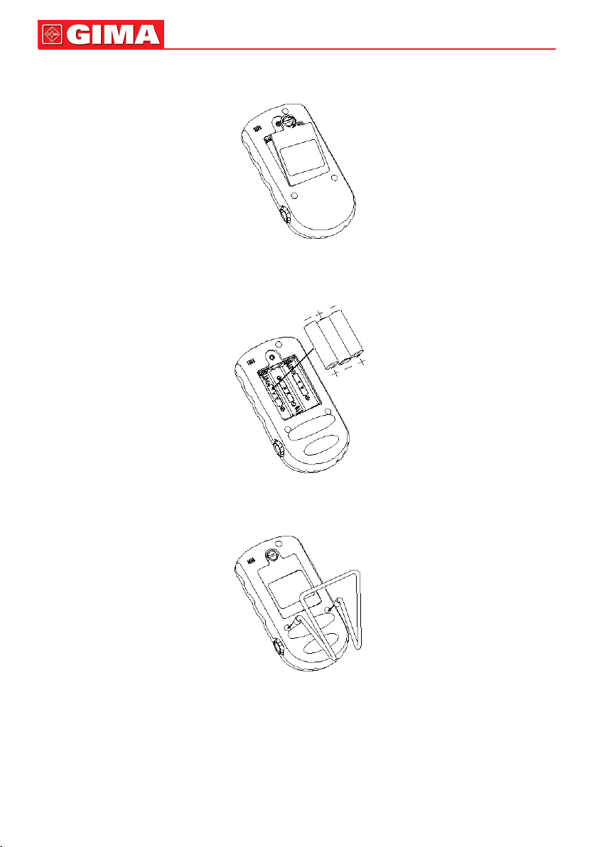
2 Installation of Battery and Holder
1) Open the rear panel with coin or an ordinary at screwdriver, as shown in Figure 2.
Figure 2
2) According to the polarity mark, insert three AA batteries into battery house, as shown in Figure 3.
18
3) Close the battery cover and lock it.
4) Fixing Holder
Figure 3
Figure 4 Fixing Holder
Page 5

19
ENGLISH
3 SpO2 Sensor Connection
3.1 Choose SpO2 Sensor Adapter
The device is equipped with universal Y-type sensors including different adapters for various measuring sites.
Three types of sensor adapters (big clip, small clip and rubber wrapper) are provided for the Y-type SpO2
sensor. They can be used to place on different measuring sites, such as ear, tongue, leg or tail. Please
select the appropriate sensor and adapter according to its shape size and the measuring site.
3.2 Install Sensor Adapter onto SpO2 Sensor
Follow the installing methods below to install the sensor adapter onto the sensor, and then connect the
SpO2 sensor cable to the connector labeled "SpO2" at the right side of the device.
After starting the oximeter, clip or wrap the sensor on to the measuring site.
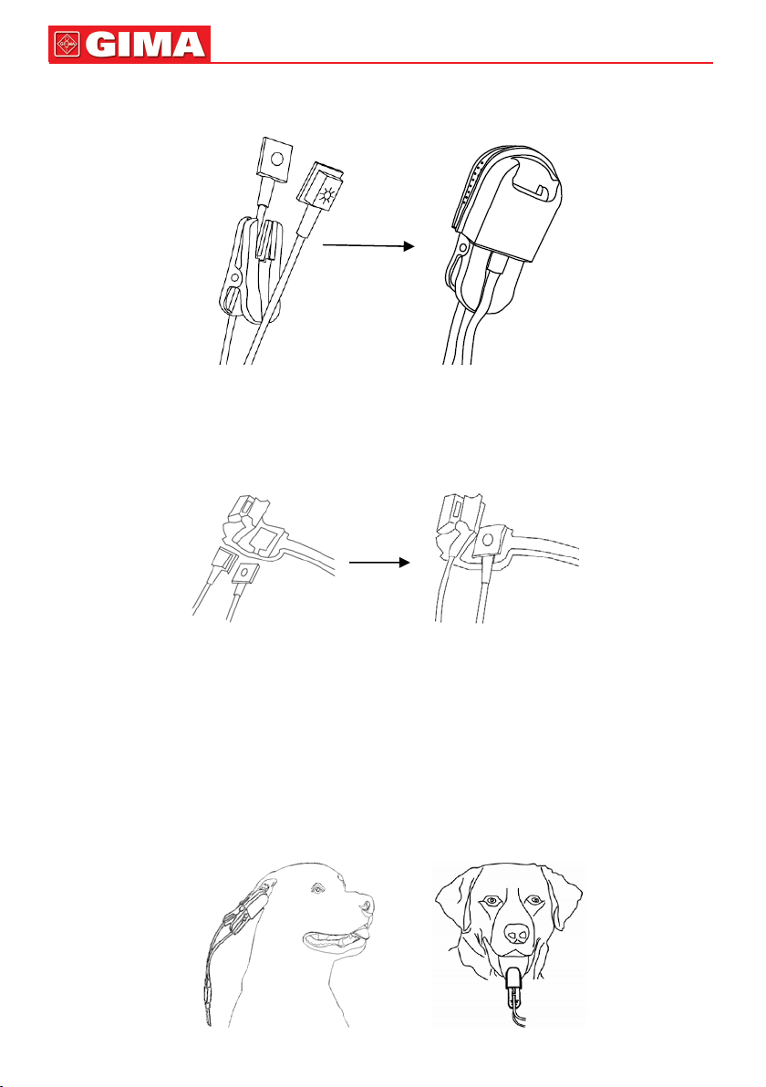
Figure 5 Clip type sensor adapter
Installation of Big Clip
1. Slip off the two rubber jackets from the clip;
2. Fix the sensor cable to the clip (Figure 6A);
3. Slide one branch of Y-type sensor (the side with coating inward) into the xing slot from the clip opening
to the stop at the end of the slot (Figure 6B), and then x the other branch;
4. Install the two rubber jackets onto the clip (Figure 6C).
Figure 6A Figure 6B Figure 6C
Big Clip installation
Page 6
ENGLISH
20
Installation of Small Clip
Follow the step 1, step 3 and step 4 mentioned in Section Installation of Big Clip and refer to Figure 7A
and Figure 7B.
Figure 7A Figure 7B
Small Clip Installation
Installation of Rubber Wrapper
1. Spread the rubber wrapper, there are two xing slots (Figure 8A);
2. Hold the rubber wrapper and press one branch of the Y-type sensor into one of the xing slots (Figure
8B), then x the other branch.
Figure 8A Figure 8B
Rubber Wrapper Installation
3.3 Placement of Veterinary SpO2 Sensor
As a general rule, measuring SpO2 and pulse rate for animal is performed when the animal is calm or
under anaesthesia, and the rst choice of measuring site is their ears, then the second choice is their
tongues. Normally the animal's tongue will slip out after anaesthesia. At rst, clip the sensor on its ear
(Figure 9) or tongue (Figure 10). Then, according to perfusion index (PI) value (greater PI is better) you
can nd an appropriate site.
Besides the ear and tongue, you can wrap the SpO2 sensor onto other places such as leg (Figure 11) or tail
(Figure 12). Since animal hair will decrease the sensitivity or even make the measurement failure, please
always choose the place with less hair under the sensor. If necessary, shave off the hair on the measuring site.
Figure 9 clip the sensor on tongue Figure 10 clip the sensor on tongue
Page 7

21
ENGLISH
Figure 11 wrap the sensor on leg Figure 12 wrap the sensor on tail
Tips for SpO2 Monitoring
A. If there is strong ambient light interference, you can use opaque thing to cover the measuring site and
the sensor. By dong so, measurement error may be decreased.
B. The light including surgery lamp, halogen lamp, uorescent lamp and infrared heating lamp can also
cause measurement error. In such condition, you can use solid black thing to cover the measuring site
and the sensor.
C. For thin tissue (without bone) such as tongue or ear, please make sure the measurement option "Thin
Tissue" in the setup menu is selected as "YES"
4 Operation
4.1 Default Screen
Press “ ” power key for 2 seconds to start the Oximeter, then insert nger into rubber cushions of the
probe, the screen will display the default screen, as shown in Figure 13.
Figure 13 Default Screen
Screen Description:
“%SpO2” “99”: SpO2 value; “99” is a percentage value;
“19:18”: Current time;
“PR 65”: Pulse rate value: 65bpm;
“ ”: Battery voltage indication;
“ ”: Data memory icon; when the data on screen becomes stable, the device will start to store data
automatically. No icon means the current data will not be stored. If the memory is full or the total number
of the records reaches 256 pieces, the earliest record will be overwritten and the icon “ ” will appear
on the screen for prompt, as shown in the gure below.
Memory full icon
Note: It is suggested that the data shall be uploaded to computer for saving, or the earliest
record will be overwritten.
Page 8

ENGLISH
22
“ ”: Alarm mute icon, when the icon becomes " " , it means that the oximeter's alarm sound is disabled.
“ ”: Pulse strength bar-graph.
Lower part displays plethysmogram.
4.2 Display Screen with PI Value
On the default screen, press “ / ” Navigation key to shift screens between default screen and
display screen with PI value.
The display screen with PI value is shown below.
Figure 14 Display Screen with PI Value
4.3 Indication for No Signal
If “check probe” prompts on screen (as shown in Figure 15), please check whether the probe cable
connects well and whether the sensor is in appropriate position.
Figure 15 Check Probe Screen
4.4 Menu Setup
On the above mentioned screens, longtime press “ ” key for entering into menu screen (as shown
in Figure 16).
Figure 16 Menu Screen
Screen Description
“SETUP”: set parameter values, refer to Chapter 4.4.1 for details.
“UPLOAD DATA”: enter into uploading status, refer to Chapter 4.4.2 for details.
"DEFAULT": enter into the factory default setting, refer to Chapter 4.4.3 for details.
“VERSION”: for viewing version number of the software, refer to Chapter 4.4.4 for details.
Page 9

23
ENGLISH
4.4.1 Setup
On the menu screen, select “SETUP” and then press “ ” key for entering into system setup screen.
The setup screen is as shown in the following gures.
Figure 17 System Setup Screen (A)
Figure 17 System Setup Screen (B)
Operation Instructions:
1. DATE: Date setting
1) When cursor stays on the Year of the date, press “ ” (Mode/OK) key to active Year option, the
cursor ashes on the Year of the date;
2) Press / (Navigation key) to adjust year.
3) Press “ ” (Power/back) key or “ ” (Mode/OK) key to conrm and exit from date setting.
4) The procedures of adjusting Month value and Day value are the same with Year adjustment.
Date Format: yy-mm-dd
Note: The setting operations of other parameters (such as TIME, RECORDING INTERVAL,
POWER SAVING etc.) are the same with date setting.
2. TIME: Time setting
3. Thin Tissue: Setting measurement option for thin tissue (without bone) such as ear pr tongue; two
options:"YES" and "NO". The factory default setting is "NO", which is for thick tissue option such as leg
or tail.
4. Alarm-SpO2: SpO2 alarm setting; the factory default value is 80%.
5. Alarm-PR Hi: Pulse Rate High limit setting, the factory default value is 140.
6. Alarm-PR Lo: Pulse Rate Low limit setting, the factory default value is 50.
7. RECORDING INTERVAL: Record interval setting; ve options: “1s, 2s, 4s, 8s” and “OFF”; When the
option is “OFF”, the device will not record real-time measurement data.
Note: The length of data record is limited to 30 seconds at least, and the maximal length
for one record is also limited to one hour (for one second interval) , 2hours (for 2 seconds
interval) 4 hours (for 4 seconds interval) or 8 hours (for 8 seconds interval).
8. POWER SAVING: power saving setting; two options: "on" and "off". The factory default setting is "on".
Page 10
ENGLISH
24
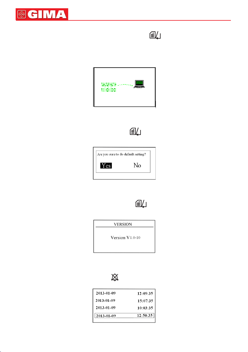
4.4.2 Upload Data
On the menu screen, select “UPLOAD DATA” and then press “ ” key for entering into connecting
status (as shown in Figure 18). When you transmit data (SpO2 and PR values) to your computer,
please let the oximeter stay in connecting status.
Do the following operation by the instruction in “Oximeter Data Manager User Manual”. The data uploading
will be activated.
Figure 18 Connecting Status Screen
4.4.3 Default
On the menu screen, select "Default " and then press “ ” key for entering into default setting screen
(as shown in Figure 19)
Figure 19 Default Setting Screen
4.4.4 Version
On the menu screen, select “VERSION” and then press “ ” key for entering into version screen (as
shown in Figure 20).
Figure 20
4.5 Data Recall
On the default display screen, longtime press “ ” ( Recall/alarm mute) key to enter into recall list screen.
Figure 21 Recall List
Page 11

25
ENGLISH
4.5.1 Data Recall
Choose one record in the recall list, then press “ ” key, the display screen will display trend graph,
as shown in Figure 22A.
Figure 22A Trend Graph Recall Screen
Screen description:
“%SpO2”: The left ordinate value is %SpO2 value;
“12:50:35”: Measuring time
“2s”: Record interval is 2 seconds.
“PR”: The right ordinate value is pulse rate value
Operation Instructions:
Press “ ” key to shift trend recall screens (as shown in Figure 22A , Figure 22B and Figure 22C)
Figure 22B Trend Graph Recall Screen
Figure 22C Trend Graph Recall Screen
Press “ / ” key to view trend graph. Press “ ” key to return to recall list screen.
4.5.2 Data Deletion
On the menu screen, longtime press “ ” key and the records list will appear. When the cursor stays
on the record needed to be deleted, longtime pressing “ ” key again, an message “Are you sure to
delete all?” prompts on the screen, as shown in Figure 23.
Figure 23
Page 12

ENGLISH
26
At this time select “Yes” and press “OK” key to delete all the selected records.
5 Technical Specications
A. Display panel: color LCD;
B. Power supply:
3x LR6 (AA) alkaline batteries or Ni-MH rechargeable batteries
Supply voltage: 3.2~5.0VDC
Operating current: <150mA
Continuous working time: >30 hours
C. SpO2 Specications
Transducer: dual-wavelength LED sensor
Measurement wavelength:
Red light: 660 nm, Infrared light: 905 nm.
Maximal optical output power: less than 2mW maximum average
Measuring range: 35~100%
Measuring accuracy: Not greater than 3% for SpO2 range from 70% to 100%
*NOTE: Accuracy dened as root-mean-square value of deviation according to ISO 9919.
Low alert setting range: 50%~99% (Default setting: 80%).
D. Pulse Rate Specications
Range: 30bpm~400bpm
Accuracy: ±2bpm or ±2% (whichever is greater)
Alert setting range: 25bpm~400bpm
Default alert setting: High: 140bpm Low: 50bpm
E. Perfusion Index Display
Range: 0~20%
F. Update rate
8 beats moving average for both SpO2 and pulse rate readings
G. Data Recording
Store data every 1/2/4/8 seconds, up to 384–hour data record.
H. Low perfusion performance
The accuracy of SpO2 and PR measurement still meet the precision described above when the modulation
amplitude is as low as 0.5%.
I. Dimensions: 145 mm (L) × 74 mm (W) × 29 mm (H)
Net Weight: 210g (including batteries)
J. Classication
The type of protection against electric shock: Internally powered equipment
The degree of protection against electric shock: Type BF applied parts.
The degree of protection against harmful ingress of liquids: Ordinary equipment without protection against
ingress of water.
Electro-Magnetic Compatibility: Group I, Class B
6 Accessories
1. A set of veterinary probe
2. A holder
3. Battery (AA) × 3
4. A User Manual
5. A Quality Certicate
6. A data cable (optional)
7. Oximeter Data Manager software (optional)
Note: The accessories are subject to change. See the Packing List for detailed items and
quantity.
Page 13

27
ENGLISH
7 Repair and Maintenance
7.1 Maintenance
The life of this device is 5 years. In order to ensure its long service life, please pay attention to the
maintenance.
• Please change the batteries when the low-voltage indicator appears.
• Please take out the batteries if the oximeter will not be used for a long time.
• The recommended storage environment of the device:
Ambient temperature: -20ºC ~60ºC
Relative humidity 10%~95%
Atmospheric pressure: 50kPa~107.4kPa
• The oximeter is calibrated in the factory before sale, there is no need to calibrate it during its life
cycle. However, if it is necessary to verify its accuracy routinely, the user can do the verication by
means of SpO2 simulator, or it can be done by the local third party test house.
7.2 Cleaning and Disinfecting Instruction
• Surface-clean sensor with a soft cloth by wetting with a solution such as 75% isopropyl alcohol, if
low-level disinfection is required, use a 1:10 bleach solution.
• Then surface-clean by a dampened cloth and let it air dry or wipe it with a cloth.
High-pressure sterilization cannot be used on the device.
Do not immerse the device in liquid.
8 Troubleshooting
Trouble
The SpO2 and Pulse
Rate display instable
Possible Reason Solution
1. The probe is not clipped correctly
on the ear or tongue.
2. The tail or leg is shaking or the
1. Clip the probe on ear or
tongue correctly and try again.
2. Let the animal keep calm.
animal is moving.
Can not turn on the
device
1. The batteries are drained or almost
drained.
2. The batteries are not inserted
properly.
1. Change batteries.
2. Reinstall batteries.
3. Please contact the local
service center.
3. The device is malfunctioning.
No Display
1. The device will power off
automatically when there is no signal
1. Normal.
2. Change batteries.
and no operation for 1 minute.
2. The batteries are almost drained.
Common Knowledge
1 Meaning of SpO
2
SpO2 is the saturation percentage of oxygen in the blood, so called O2 concentration in the blood; it is
dened by the percentage of oxyhemoglobin (HbO2) in the total hemoglobin of the arterial blood. SpO2
is an important physiological parameter to reect the respiration function; it is calculated by the following
method: SpO2 = HbO2/ (HbO2 +Hb)×100%
HbO2 are the oxyhemoglobins (oxygenized hemoglobin), Hb are those hemoglobins which release oxygen.
2 Principle of Measurement
Based on Lamber-Beer law, the light absorbance of a given substance is directly proportional with its
density or concentration. When the light with certain wavelength emits on human tissue, the measured
intensity of light after absorption, reecting and attenuation in tissue can reect the structure character
of the tissue by which the light passes. Due to that oxygenated hemoglobin (HbO2) and deoxygenated
hemoglobin (Hb) have different absorption character in the spectrum range from red to infrared light
Page 14

ENGLISH
28
(600nm~1000nm wavelength), by using these characteristics, SpO2 can be determined. SpO2 measured
by this oximeter is the functional oxygen saturation -- a percentage of the hemoglobin that can transport
oxygen. In contrast, hemoximeters report fractional oxygen saturation – a percentage of all measured
hemoglobin, including dysfunctional hemoglobin, such as carboxyhemoglobin or metahemoglobin.
Clinical application of pulse oximeters: SpO2 is an important physiological parameter to reect the
respiration and ventilation function, so SpO2 monitoring used in clinical becomes more popularly, such
as monitoring the patient with serious respiratory disease, the patient under anesthesia during operation,
premature and neonate. The status of SpO2 can be determined in time by measurement and nd the
hypoxemia patient earlier, thereby preventing or reducing accidental death caused by hypoxia effectively.
3 Normal SpO2 Range and Default Low Limit
In campagna area, healthy people’s SpO2 value is greater than 94%, so the values below 94% are
determined as hypoxia. SpO2<90% is considered as the default threshold for determining anoxia by most
researchers, so SpO2 low limit of the oximeter is set as 90% generally.
4 Factors affecting SpO2 accuracy (interference reason)
- Intravascular dyes such as indocyanine green or methylene blue
- Exposure to excessive illumination, such as surgical lamps, bilirubin lamps, uorescent lights, infrared
heating lamps, or direct sunlight.
- Vascular dyes or external used color-up product such as nail enamel or color skin care
- Excessive patient movement
- Placement of a sensor on an extremity with a blood pressure cuff, arterial catheter, or intravascular line
- Exposure to the chamber with High pressure oxygen
- There is an arterial occlusion proximal to the sensor
- Blood vessel contraction caused by peripheral vessel hyperkinesias or body temperature decreasing
5 Factors causing low SpO2 value (pathology reason)
- Hypoxemia disease, functional lack of HbO
2
- Pigmentation or abnormal oxyhemoglobin level
- Abnormal oxyhemoglobin variation
- Methemoglobin disease
- Sulfhemoglobinemia or arterial occlusion exists near sensor
- Obvious venous pulsations
- Peripheral arterial pulsation becomes weak
- Peripheral blood supply is not enough
Appendix
Key of Symbols
Symbol Description
%SpO2 The pulse oxygen saturation
PI Perfusion Index
PR
Symbols
on the
screen
Pulse rate
(Unit: beats per minute)
Low battery voltage
Alarm Icon
Memory Icon
Memory full
Page 15

29
ENGLISH
Symbol Description
SpO2 SpO2 probe connector
Power/Back Key
Mode/OK Key
Recall/Alarm mute
/
Symbols
on the
panels
Disposal: The product must not be disposed of along with other domestic waste. The users
must dispose of this equipment by bringing it to a specic recycling point for electric and
electronic equipment.
For further information on recycling points contact the local authorities, the local recycling center
or the shop where the product was purchased. If the equipment is not disposed of correctly,
nes or penalties may be applied in accordance with the national legislation and regulations.
Navigation Key
Data Interface
Medical Device complies
with Directive 93/42/EEC
Serial number
Date of manufacture
Authorised representative
in the European
community
Symbol Description
Manufacturer (including
address)
Type BF applied part
Caution: read instructions
(warnings) carefully
WEEE disposal
Symbols
on the
panels
Keep away from sunlight
Keep in a cool, dry place
Follow instructions for use
Product code
Lot number
GIMA WARRANTY CONDITIONS
Congratulations for purchasing a GIMA product.
This product meets high qualitative standards both as regards the material and the production. The
warranty is valid for 12 months from the date of supply of GIMA.
During the period of validity of the warranty, GIMA will repair and/or replace free of charge all the defected
parts due to production reasons. Labor costs and personnel traveling expenses and packaging not
included. All components subject to wear are not included in the warranty.
The repair or replacement performed during the warranty period shall not extend the warranty.
The warranty is void in the following cases: repairs performed by unauthorized personnel or with nonoriginal spare parts, defects caused by negligence or incorrect use.
GIMA cannot be held responsible for malfunctioning on electronic devices or software due to outside
agents such as: voltage changes, electro-magnetic elds, radio interferences, etc.
The warranty is void if the above regulations are not observed and if the serial code (if available) has
been removed, cancelled or changed.
The defected products must be returned only to the dealer the product was purchased from. Products
sent to GIMA will be rejected.
Page 16

30
Page 17

31
Page 18

 Loading...