

Page 1
PROFESSIONAL MEDICAL PRODUCTS
MISURATORE DI PRESSIONE LEO CON SOFTWARE
LEO BLOOD PRESSURE MONITOR
WITH SOFTWARE
TENSIOMÈTRE LEO AVEC LOGICIEL
DE LEO MEDIDOR DE PRESIÓN
CON SOFTWARE
MEDIDOR DA TENSÃO LEO COM SOFTWARE
32902 / CONTEC08A
CONTEC MEDICAL SYSTEMS CO., LTD
No.112 Qinhuang West Street, Economic & Technical Development Zone,
Qinhuangdao, Hebei Province, PEOPLE’S REPUBLIC OF CHINA
Made in China
Shanghai International Holding Corp. GmbH (Europe)
Eiffestrasse 80, 20537 Hamburg, Germany
Importato da / Imported by / Importé par / Importado por / Importado por:
Gima S.p.A.
Via Marconi, 1 - 20060 Gessate (MI) Italy
gima@gimaitaly.com - export@gimaitaly.com
www.gimaitaly.com
M32902-M-Rev.2.05.20
0123
Page 2

ENGLISH
50
Foreword
Please read the User Manual carefully before using this product. The User Manual which describes the operating
procedures should be followed strictly. This manual detailed introduce the steps must be noted when using the product,
operation which may result in abnormal, the risk may cause personal injury and product damage and other contents, refer
to the chapters for details. Any anomalies or personal injury and device damage arising from use, maintain, store do not
follow requirements of the User Manual.
Note: Please read the User Manual carefully before using this product.
Described in this User Manual is in accordance with practical situation of the product. In case of modications and software
upgrades, the information contained in this document is subject to change without notice.
The warning items
Before using this product, you should consider the safety and efcacy of the following described:
• Described each measurement results combined with clinical symptoms by qualied doctors.
• The reliability and operation of using this product whether meets the operation of this manual relate to the maintenance
instructions.
• The intended operator of this product may be the patient.
• Do not perform maintenance and service while the device is in use.
Warning: Replace accessories which not provided by our company may lead to the occurrence of errors.
Replace adapters, cuffs or SpO2 probes at will may result in wrong measurement results. Without our company
or other approved maintenance organizations trained service personnel should not try to maintain the product.
Page 3

51
ENGLISH
Contents
Chapter 1 Safety Precautions ....................................................................................................................................... 53
1.1 Operation for AC Adapter (Separate Sale) ............................................................................................... 56
1.2 Operation for Battery ................................................................................................................................ 56
Chapter 2 Main Unit ....................................................................................................................................................... 58
Chapter 3 External Interfaces ....................................................................................................................................... 61
Chapter 4 Battery/AC Adapter Installation ..................................................................................................................63
4.1 Battery Installation .................................................................................................................................... 63
4.2 Usage of power adapter ........................................................................................................................... 64
Chapter 5 Button Functions .......................................................................................................................................... 64
Chapter 6 Setting the Date and Time ........................................................................................................................... 65
Chapter 7 About Unit ..................................................................................................................................................... 66
Chapter 8 User Switch ................................................................................................................................................... 66
Chapter 9 Over-limit Prompt Function ......................................................................................................................... 67
9.1 Physiological parameter over-limit prompt ............................................................................................... 67
9.2 Technical parameter over-limit prompt ..................................................................................................... 68
Chapter 10 The Usage Method of Sphygmomanometer .............................................................................................. 68
10.1 Accurate Measurement Way ..................................................................................................................68
10.2 Applying the Cuff ....................................................................................................................................70
10.3 BP Measurement .................................................................................................................................... 72
Chapter 11 Memory Function.......................................................................................................................................... 73
11.1 Review Memory Values .......................................................................................................................... 73
11.2 Delete Memory Values ............................................................................................................................ 73
Chapter 12 SpO2 Measurement Function ...................................................................................................................... 74
Chapter 13 SpO2 Measurement Method ........................................................................................................................ 77
Page 4

ENGLISH
Chapter 14 Installation of the Software.......................................................................................................................... 78
14.1 Demand of Editor.................................................................................................................................... 78
14.2 Installation of Software ........................................................................................................................... 78
Chapter 15 Error Message............................................................................................................................................... 79
Chapter 16 Troubleshooting ........................................................................................................................................... 80
Chapter 17 Keys and Symbols........................................................................................................................................ 82
Chapter 18 Maintenance, Cleaning and Keeping .......................................................................................................... 83
Chapter 19 NIBP Specication ........................................................................................................................................ 85
Chapter 20 SpO2 Specication ....................................................................................................................................... 88
Appendix ........................................................................................................................................................................ 89
52
Page 5
53
ENGLISH
Chapter 1
SAFETY PRECAUTIONS
• In order to use it correctly, please read the “Safety Precautions” carefully before using it.
• Operators do not need professional training, but should use this product after fully understanding the requirements in this
manual.
• To prevent users from suffering damage or loss due to improper use, please refer to “Safety Precautions” and use this
product properly.
Note
If not use correctly, it exists the possibility of damage for personnel and goods.
Good damage means the damage of house, property, domestic animal and pet.
Contraindication
No.
Warning
• You must not perform NIBP measurements on patients with sickle-cell disease or under any condition which the skin is
damaged or expected to be damaged.
• For patients with severe disturbances of blood coagulation, whether automatically measure the blood pressure should be
based on the clinical evaluation, because limb friction with the cuff may cause the risk of hematoma.
• For severe blood circulation disorder or arrhythmia patients, please use the device under the guidance of a doctor. If the
arm is squeezed during measurement, it may cause acute internal hemorrhage or inaccurate measurement results.
Measurement Limitations
To different patient conditions, the oscillometric measurement has certain limitations. The measurement is in search of
regular arterial pressure pulse. In those circumstances when the patient’s condition makes it difcult to detect, the measurement becomes unreliable and measuring time increases. The user should be aware that the following conditions could
interfere with the measurement, making the measurement unreliable or longer to derive. In some cases, the patient’s
condition will make a measurement impossible.
Page 6

ENGLISH
54
Patient Movement
Measurements will be unreliable or can not perform if the patient is moving, shivering or having convulsions. These motions
may interfere with the detection of the arterial pressure pulses. In addition, the measurement time will be prolonged.
Cardiac Arrhythmia’s
Measurements will be unreliable and may not be possible if the patient’s cardiac arrhythmia has caused an irregular heartbeat. The measuring time thus will be prolonged.
Heart-lung Machine
Measurements will not be possible if the patient is connected to a heart-lung machine.
Pressure Changes
Measurements will be unreliable and may not be possible if the patient’s blood pressure is changing rapidly over the period
of time during which the arterial pressure pulses are being analyzed to obtain the measurement.
Severe Shock
If the patient is in severe shock or hypothermia, measurements will be unreliable since reduced blood ow to the peripheries will cause reduced pulsation of the arteries.
Heart Rate Extremes
Measurements can not be made at a heart rate of less than 40 bpm and greater than 240 bpm.
Round Patient
The thick fat layer of body will reduce the measurement accuracy, because the fat that come from the shock of arteries can
not access the cuffs due to the damping.
Warning
Self-diagnosis and treatment using measured results may be dangerous. Follow the instructions of your physician.
Please hand measurement results to the doctor who knows your health and accept diagnosis.
For Infant and the person who can’t express oneself, please use the device under the guidance of a doctor.
Otherwise it may cause accident or dissension.
Please do not use for any other purpose except BP measurement.
Otherwise it may cause accident or holdback
Please use special cuff.
Otherwise it is possible that measurement result is incorrect.
Page 7

55
ENGLISH
Please do not keep the cuff in the over-inated state for a long time.
Otherwise it may cause risk.
Do not use the device in the case of there are ammable anesthetic gasses mixing with the air or nitrous oxide.
Otherwise it may cause risk.
If liquid splashes on the device or accessories, especially when liquids may enter the pipe or device, stop using
and contact the service department.
Otherwise it may cause risk.
Dispose of the packaging material, observing the applicable waste control regulations and keeping it out of children’s reach.
Otherwise it may cause harm to the environment or children.
Please use approved accessories for the device and check that the device and accessories are working properly
and safely before use.
Otherwise the measurement result may be inaccurate or an accident may occur.
When the device is accidentally damp, it should be placed in a dry and ventilated place for a period of time to
dissipate moisture.
Otherwise the device may be damaged due to moisture.
Do not store and transport the device outside the specied environment.
Otherwise it may cause measurement error.
It is recommended that you check if there is any damage on the device or the accessories regularly, if you nd any
damage, stop using it, and contact the biomedical engineer of the hospital or our Customer Service immediately.
Do not disassemble, repair and modify the device without permission.
Otherwise it cannot be accurately measured.
This device can not be used on mobile transport platforms.
Otherwise it may cause measurement error.
This device can not be used on a tilted tabletop.
Otherwise there is a risk of falling.
Dispose of packaging materials, waste batteries and end-of-life products in accordance with local laws and regulations.
The end-of-life products and materials are properly disposed of by the user in accordance with the authority’s decree.
Replace accessories which not provided by our company may lead to the occurrence of errors.
Page 8

ENGLISH
Without our company or other approved maintenance organizations trained service personnel should not try to
maintain the product.
This device can only be used for one test object at a time.
If the small parts on the device are inhaled or swallowed, please consult a doctor promptly.
The device and accessories are processed with allergenic materials. If you are allergic to it , stop using this product.
After pressing the power button, if the device has display fault such as white screen, blurred screen or no display
content, please contact our company.
The device shall comply with the standard IEC 80601-2-30:Particular requirements for basic safety and essential performance of automated non-invasive sphygmomanometers.
56
1.1 Operation for AC Adapter (Separate Sale)
Note
The device can be powered by a power adapter that is a part of the medical electrical system.
Be sure to use the dedicated medical grade power adapter of this device.
Otherwise it may cause trouble
Dedicated power adapter must use AC 100 V~240 V
Otherwise it may cause re or electric shock.
When there is breakage of dedicated power adapter plug or wire, please do not use it.
Otherwise it may cause re or electric shock.
Please do not plug or unplug the adapter on the socket with wet hands.
Otherwise it may cause electric shock or injury.
1.2 Operation for Battery
Note
Please use 4 “AA” size manganese or alkaline batteries, do not use batteries of other types.
Otherwise it may cause re.
Page 9

57
ENGLISH
New and old batteries, different kinds batteries can not be put off.
Otherwise it may cause battery leakage, heat, rupture, and damage to Electronic Sphygmomanometer.
Please don’t put wrong the positive and negative of battery. When the batteries power exhausts, replace with four
new batteries at the same time.
Please take out the batteries when you do not use the device for a long time (3 months or more).
Otherwise it may cause battery leakage, heat, rupture, and damage to Electronic Sphygmomanometer.
If electrolyte of the batteries immodestly get in your eyes, immediately rinse with plenty of clean water.
It will cause blindness or other hazards, should immediately go to the nearest hospital for treatment.
If electrolyte of the batteries immodestly glues on the skin or the clothes, immediately rinse with plenty of clean
water.
Otherwise it may hurt the skin.
Advice
Do not strike or drop the device.
Do not inate before the cuff wraps around the arm.
Do not inect the cuff and the air tube forcibly.
Description of functions:
The Sphygmomanometer apply to measure the non-invasive blood pressure and SpO2 of human (adult, children, neonate),
uses three-user mode, each user can store 100 items records of measurement results at most. Each record includes
detailed measuring time, systolic pressure, diastolic pressure, average pressure, pulse rate and record number, etc. With
2.8 inch color LCD screen, clear interface, the function of data review is complete. User can implement ON/OFF, manual
measuring, system setup, parameters change and other operations with seven buttons which are located on the front panel
of the device.
The Sphygmomanometer uses audible and visual prompt, when the battery power is low, the buzzer will intermittent buzzing and LCD screen displays “Low Power” to prompt user replace batteries. When the measurement data exceeds the set
prompt limit, the font color of measurement results will change to red and the audible prompt will occur, user can open and
close the prompt sound according to needs. With timing shutdown function, if there is no operation and SpO2 measure-
ment, the device will automatically turn off after 2 minutes. With USB interface, Users can send measurement results to PC.
Refer to the help or explication of the related software for specic operation.
Page 10
ENGLISH
58
Purpose:
The device apply to measure the non-invasive blood pressure and SpO2 (optional) of human. Record parameter value of
blood pressure to provide the reference for the health care professional.
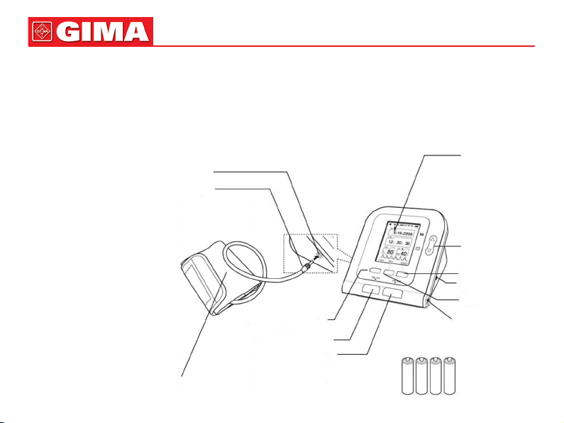
Chapter 2
MAIN UNIT
The production is in the package.
Open the package and conrm
whether the production is whole.
Cuff plug
Cuff air plug jack
USER SWITCH button
ON/OFF button
START/STOP button
Display
UP/DOWN button
MEMORY button
AC adapter jack
MENU button
USB plug jack
Adult cuff
Dry battery
Page 11
59
ENGLISH
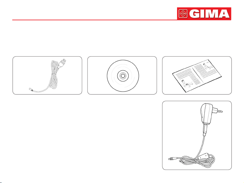
Accessories:
Specication: limb circumference 22-32 cm (middle part of upper arm), please select suited cuff when measuring children
or other limb circumference.
USB Data Line Software CD User Manual
Optional Accessories:
AC adapter
Input: voltage: AC 100 V~240 V
Frequency: 50 Hz/60 HZ
Rated current: AC 150 mA
Output: DC 6.0 V±0.2 V 1.0 A
or DC5.0 V±0.2 V 1.0 A
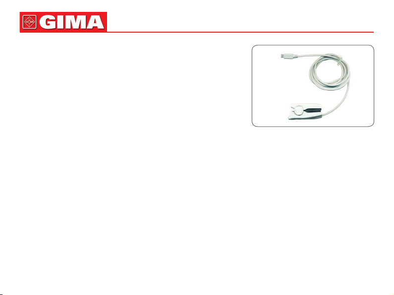
SpO2 probe: Integrated SpO2 probe
(This part is only suitable for European Union market)
A. SpO2 measurement
Range:0%~100%
Error: 70~100%: ±2%; Below 70%: unspecied
Resolution: 1%
Page 12
ENGLISH
60
Note: because SpO2 probe measurements are statistically distributed,
only about two-thirds of SpO2 probe measurements can be expected to
fall within ±Arms of the value measured by a CO-OXIMETER.
B. Pulse rate measurement
Range:30 bpm~250 bpm
Error: ±2 bpm or ±2% (select the larger)
Resolution: 1bpm
C. Optical sensor: red light(wavelength: 660 nm, output power less than
6.65 mW) infrared light(wavelength: 880 nm, output power less than
6.75 mW). Optical sensors are light-emitting components that affect oth-
er medical devices that use this wavelength range. This information may
be useful to clinicians who perform optical therapy.
D. Error in weak lling condition: SpO2 and pulse rate can be shown correctly when pulse-lling ratio is 0.4%. SpO2 error
is ±4%; when measuring range is 30 bpm~100 bpm, pulse rate error is ±2 bpm; when measuring range is 100 bpm~250
bpm, pulse rate error is ±2%.
Note:
• The optional probe of the Sphygmomanometer is an integrated SpO2 probe, the measuring part is integrated with the
probe;
• The service life of the integrated SpO2 probe is three years.
Cuff:
Choose the right cuff based on the patient’s upper arm circumference, there are several suitable cuffs(range of limb circumference, middle part of upper arm)
the range of limb circumference is 6-11 cm
the range of limb circumference is 10-19 cm
the range of limb circumference is 18-26 cm
the range of limb circumference is 32-43 cm
Page 13
61
Note
• The cuff is a consumable. Calculate by measuring 6 times a day(3 times each morning and evening), the service life of
the cuff is about 1 year.(using our experimental conditions).
• In order to correctly measure blood pressure, please replace the cuff in time.
• If the cuff leaks, please contact our company to buy a new one. The cuff purchased separately does not include the airway
tube plug. When replacing, please do not throw the airway tube plug away, install it on the new cuff.
Note
When the product and accessories described in this manual are about to exceed the period of use, they must be disposed
according to relevant product handling specication. If you want to know more information, please contact our company or
representative organization.
.
ENGLISH
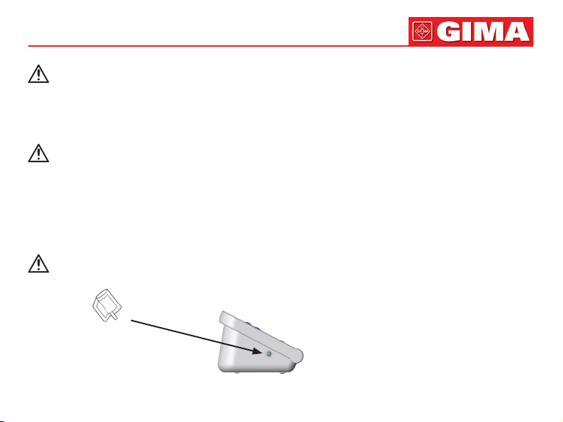
Chapter 3
EXTERNAL INTERFACES
Note
When removing NIBP cuff, please take plug at the front of the windpipe to pull out.
• Cuff socket ( is cuff identier)
Left side
Page 14
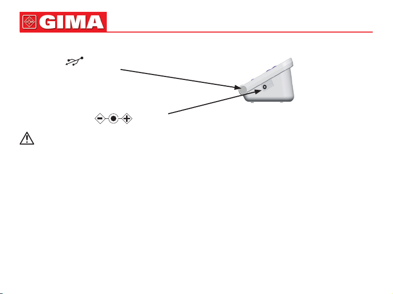
ENGLISH
62
The right side of the device is USB socket and power adapter socket
• USB socket ( is USB identier)
Right side
• Power adapter socket ( is power socket identier)
Note
All analog and digital equipment connected to this device must be certied to IEC standards(such as IEC60950:
Information technology equipment-Safety and IEC60601-1: Medical electrical equipment-Safety), and all equipment should be connected to in accordance with the requirement of the valid version of the IEC60601-1-1 system
standard. The person connecting the additional equipment to the signal input and output port is responsible for
whether the system complies with the IEC60601-1 standard.
Page 15
63
ENGLISH
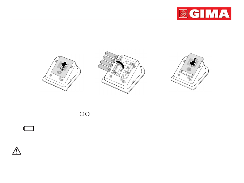
Chapter 4
BATTERY/AC ADAPTER INSTALLATION
The product can use battery or AC adapter as power source.
1 2 3
4.1 Battery Installation
1. Demount the battery cover in the direction of the arrow.
2. Install “AA” batteries according to
3. Slide to close the battery cover.
Icon “ ”: the batteries power will exhaust. Replace with four new batteries (the same sort) at the same time. Test while
low power may cause data deviation and other problems.
Turn the unit off before replacing the batteries.
Note
When the battery reaches the end of its life, or if the battery is found to have odor, deformation, discoloration or
distortion, stop using the battery and dispose of the used battery in accordance with local regulations, otherwise
it will cause environmental pollution.
+ -
polarities.
Page 16

ENGLISH
64
4.2 Usage of power adapter
1. Connect the sphygmomanometer and the power adapter. Insert the power adapter plug into the power adapter socket
on the right side of the device.
2. Please insert the power plug of the adapter into the AC 100 V~240 V socket.
Note
The device can be disconnected from the power supply network by unplugging the adapter plug.
When cut off the power supply, rst cut off the connection of power socket and the regulated power supply, then
cut off the connection of regulated power supply and the sphygmomanometer.
Please be sure to use dedicated medical grade power adapter.
Note
When regulated power supply and batteries are both used at the same time, the battery power will not be consumed.
Switch regulated power supply and battery as power supply when the device is off, otherwise, the device may
shutdown due to power failure.
The device can be used normally after it is turned on ,without waiting for the device to be prepared.
Chapter 5
BUTTON FUNCTIONS
All the operations to the Electronic Sphygmomanometer are through the buttons. The names of the buttons are above
them. They are:
• [ON/OFF] ON/OFF button. Press this button to turn on/off the device
• [START/STOP] Press it to inate the cuff and start a blood pressure measurement. During measuring, press it
to cancel the measurement and deate the cuff.
Page 17

65
ENGLISH
• At all levels interface, the three buttons correspond respectively with the text prompts
• Up and down buttons, respectively carry on the functions of moving the cursor up and down, changing the param-
eters and switching the status.
below the LCD screen, pressing any button will carry on the corresponding function,
eg: [MENU] [ENTER] [LIST] [USER] etc.
Chapter 6
SETTING THE DATE AND TIME
It is necessary to set date and time after power on.
The Electronic Sphygmomanometer can automatically stores measurement results with date and time.
If batteries power exhausts or removed, the time to stop.
At the moment, please reset date and time.
The Electronic Sphygmomanometer stores measure results of three users automatically, and up to 100 items for every user.
If the date and time are set correctly, the date and time when measuring will be correct in the memory, otherwise it may not
be correct. The results can be uploaded to PC via USB and processed with the PC software.
1. There are two modes of time setting:
(1) When using the Sphygmomanometer for the rst time or after the Sphygmomanometer has been placed without pow-
er supply for a certain time(more than 3 minutes), after power on, there is a prompt of time error on the main interface,
set date and time with [UP], [DOWN] and [ENTER] button.
(2) Press [MENU] button on the main interface to enter system menu, then enter [SYSTEM TIME], item, the current time
will be displayed on the screen. Set date and time with [UP], [DOWN] and [ENTER] button.
2. After setting, select [CONFIRM] option and press [ENTER] button to conrm the setting value. If you do not want to
change the time, select [EXIT] option and press [ENTER] button to return to the previous menu.
Note
The range of year is from 2010 to 2099. When the year reaches 2099, pressing the [UP] button will return to 2010.
Page 18
ENGLISH
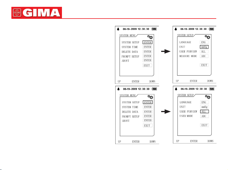
Chapter 7
ABOUT UNIT
There are two units: “mmHg” and “kPa”.
The default is: “mmHg”.
Enter the [SYSTEM SETUP] submenu in [SYSTEM
MENU], then select [UNIT] option to switch units be-
tween “mmHg” and “kPa”.
Chapter 8
USER SWITCH
The Electronic Sphygmomanometer stores the measure
results of three users automatically, and up to 100 items
for every user.
Press [USER] button in main interface to switch users.
Or press [USER PREVIEW] item in [SYSTEM SETUP]
menu to switch users.
66
Page 19

67
Note
When the [USER PREVIEW] is set to [ALL], , current user
can be switched under main interface; when set to a certain user, it will not be able to switch under main interface.
User type can be set to adult, pediatric and neonatal three
different kinds, setting method is as follows:
ENGLISH
Chapter 9
OVER-LIMIT PROMPT FUNCTION
The Sphygmomanometer has two kinds of reminding methods: the technical parameter over-limit prompt and the physiological parameter over-limit prompt.
9.1 Physiological parameter over-limit prompt
The sphygmomanometer has the function of over-limit prompt, the user can press [MENU] button to enter system menu,
select [PROMPT SETUP] option to enter its interface, then set the limit value of blood pressure. When the BP measurement
result is higher than the high limit or lower than the low limit and the prompt is ON, the physiological prompt will occur; in
[PROMPT SETUP] interface, select [SpO2 PROMPT] option to enter its interface, when the SpO2 measurement result is
higher than the high limit or lower than the low limit and the prompt is ON, the physiological prompt will occur.
In the state of physiological prompt, press any button to cancel the prompt and it does not affect the next prompt; the prompt
can be closed permanently with prompt switch of the prompt setup menu until the prompt switch be opened again.
Page 20

ENGLISH
68
9.2 Technical parameter over-limit prompt
When power is about to exhaust and prompt is ON, the prompt will occur. This prompt can not be cancelled unless being
closed or the power replaced.
Chapter 10
THE USAGE METHOD OF SPHYGMOMANOMETER
10.1 Accurate Measurement Way
Measurement in quiet and relaxing state.
1. Adopt a comfortable sitting position, use back and arms to support the body.
2. Place your elbow on a table, the palm faces up and the body is relaxed.
3. The cuff is level with your heart.
4. Feet at on the oor, and do not cross your legs.
Page 21

69
ENGLISH
Advice
Try to measure your blood pressure at the same time each day with the same arm and the same pose for consistency.
The high and low location of cuff will cause changes in measure results.
Do not touch the sphygmomanometer, cuff and windpipe during measure.
Measurements should be taken in a quiet place and the body relax.
Remain still 4~5 minutes before measurement.
Do not talk and movement during the measurement. Relax the body, do not let the muscle activity.
Wait 4~5 minutes between measurements.
Do not use precision instrument near the Sphygmomanometer.
Warning
When repeatedly measuring, the accurate blood pressure value may not be measured due to congestion in the arm. Please
measure after the blood ow is smooth.
Repeated measurement for a long period of time, limbs rubbing with the cuff may be accompanied by purpura, ischemia
and nerve damage. When measurement a patient, it is necessary to frequently check the color, warmth and sensitivity of
the distal of the limb. Once any abnormalities are observed, place the cuff in another position or stop the blood pressure
measurement immediately.
Please use the device at an environment of suitable temperature and humidity(refer to Chapter19), otherwise it will cause
measurement error.
Do not twist or wrap the airway tube. It can cause constant pressure in the cuff which can block blood ow and cause
serious damage to the patient.
Do not use the cuff on the injured area, which will cause more serious damage to the area.
Do not use the cuff in the area where the treatment is being performed inside blood vessel or the arteriovenous connection.
This may cause temporary blockage of blood ow and cause injury to the patient.
Do not use the cuff on the side of the mastectomy.
When using the cuff to pressurize, some of the body’s functions may temporarily weaken. Do not use the measurement
medical electrical equipment at the appropriate arm position.
Page 22

ENGLISH
Do not move during measurement, it will have a delayed effect on the patient’s blood ow.
The device need to be placed for 2 hours from the minimum storage temperature to being ready for its intended use.
The device need to be placed for 4 hours from the highest storage temperature to being ready for its intended use.
Note
The following conditions may also cause changes in the blood pressure measurement value.
Take the measurement in one hour after meal or after drinking alcohol, coffee or after smoking, exercise, bathing.
Using incorrect posture such as standing or lying down, etc.
The patient speak or move his body during measurement.
When measuring, the patient is nervous, excited, emotional instability.
The room temperature rise or fall sharply, or the environment of measurement often changes.
Measuring in a moving vehicle.
The high and low location of cuff will cause changes in measurement results.
Continuous measurement for a long time.
70
10.2 Applying the Cuff
Both left and right arm can be measured.
Bare your arm or cloth close-tting clothing during measurement.
Carry out the operation in a room with comfortable temperature.
When measuring, take the thick clothes off instead of rolling up the sleeves.
In order to measure accurately, pay attention to applying the cuff properly
(left arm).
1. Insert the arm cuff air plug in the cuff socket of sphygmomanometer.
Page 23

71
ENGLISH
2. Stretch cuff into a barrel for the arm can conformable enter into the barrel.
3. Left arm penetrate through the cuff, the air tube of the cuff will pass the top of
your palm.
4. Wrap the cuff to your upper arm. Make the air tube inside the forearm and
aligned with your middle nger.
5. The bottom of the cuff should be approximately 2cm~3cm above your elbow.
6. Be xed with cloths, and wrapped tight cuff, the arm and the cuff should not have
gaps.
Page 24

ENGLISH
72
10.3 BP Measurement
The user can be set to three different types(adult, pediatric and newborn). Set it through the [USER TYPE] option in [SYS-
TEM SETUP] menu.
Note
When the patient is a newborn, please select the newborn mode and select the appropriate size of the cuff to
measure, otherwise it may cause harm to the patient.
1. Press [START/STOP] button to start measurement.
During measurement, please keep correct pose and quiet state, do not move.
If you want to abort the measurement
Press [START/STOP] button, the device will stop inating, and release the air from the cuff.
2. Conrm the Measurement Value
The measurement value can be stored automatically, using [memory function] (refer to Chapter11).
*Self-diagnosis and treatment using measured results may be dangerous. Follow the instructions of your physician.
Note
• Wait at least 4-5 minutes between measurements
When repeatedly measuring, the accurate blood pressure value may not be measured due to congestion in the arm.
Please measure after the blood ow is smooth.
• When some factors affect the measurement results in measurement process, error messages will appear on the screen,
you can obviate the malfunction and restart a measurement.
• The minimum value of the patient’s physiological signal is the minimum limit that the device can measure. The device
may obtain inaccurate measurement results when it is operated below the minimum amplitude or minimum value of the
patient’s physiological signal.
3. In the state of the physiological parameter over-limit prompt is not triggered, press any button to carry on the correspond-
ing button function; in audio prompt state, press any button (except [ON/OFF] button) to clear up the audio prompt.
4. Take off the cuff, press [ON/OFF] button to turn the device off.
Page 25

73
ENGLISH
Chapter 11
MEMORY FUNCTION
The sphygmomanometer is designed to store the blood pressure, pulse rate values and the date and time when measured,
which are up to 100 groups. If there have been stored 100 groups, the earliest results will be deleted when saving the 101
group of measurement results.
11.1 Review Memory Values
1. In the main interface (interface when starting-up), press [MEMORY] button to review the latest
measured values in big-font with the serial number from 1 to 100.
2. Press [UP]/[DOWN] button to circularly switch the former measurement values.
*The right gure shows that there is no measurement result can be displayed.
3. Press [LIST] button to display the data list interface.
4. Press [TREND] button to display trend interface.
End to display the measurement values:
Press [EXIT] button to return to the main interface or hold [ON/OFF] button to turn the device
off.
11.2 Delete Memory Values
Users can delete all memory values of a user instead of separately delete one memory value.
1. Press [MENU] button to enter the system menu, select [DELETE DATA] option to enter its interface, select the user
whose data to be deleted, after conrming again, all measurement results of the selected user will be deleted.
2. Finish Operation
Select [CONFIRM] or [EXIT] to return to the previous menu, or hold [ON/OFF] button to turn the device off.
Page 26

ENGLISH
74
Chapter 12
SpO2 MEASUREMENT FUNCTION
(This chapter is only suitable for European Union market)
Precautions during SpO2 Measurement:
Note
• Make sure the nail covers the light. The probe cable should be on the backside of the hand. Improper probe placement
or improper contact with the test site will inuence the measurement.
• SpO2 value always displays in the xed place.
• The test site shall not use external coloring agent (such as nail polish, dyestuff or color skin care products, etc.), otherwise
it will affect the measurement.
• The ngers which are too cold or too thin may affect the measure accuracy, please insert the thicker nger such as thumb
or middle nger deeply enough into the probe.
• The SpO2 probe is suitable for children and adults (not suitable for infants and newborns). The device may not applicable
for all patients. If you are unable to achieve stable readings, stop using it.
• Data averaging and signal processing will delay the SpO2 displaying and data values transmitting. The update time of
measurement data is less than 30 seconds, when signal attenuation, weak perfusion or other interference appears, it will
result in time increasing of dynamic data averaging, which depends on the PR value.
• The PLETH waveforms are not normalized, which is used as the indicator for signal incompleteness. So the accuracy of
the measured values may decrease when the waveform does not tend to smooth and stable. When the waveform tends
to smooth and stable, the reading is optimal value, and the waveform at the moment is the most standard one..
• The temperature for the contact surface of the device with the body is less than 41℃, and this temperature value is
measured by a temperature measuring device.
• The device does not provide over-limit alarm function, so it is inapplicable for using in places where need such function.
• The SpO2 probe has been calibrated before leaving factory. It does not need to be calibrated during maintenance.
• SpO2 probe is calibrated to show functional oxygen saturation.
• The SpO2 probe and photoelectric receiving tube should be arranged in a way with the subject’s arteriole in a position
there between. Make sure the optical path is free from any optical obstacles like rubberized fabric, to avoid inaccurate
measurement.
Page 27

75
ENGLISH
• As the measure is taken on the basis of arteriole pulse, substantial pulsating blood ow of subject is required. For a sub-
ject with weak pulse due to shock, low ambient/body temperature, major bleeding, or use of vascular contracting drug,
the SpO2 waveform (PLETH) will decrease. In this case, the measurement will be more sensitive to interference.
• The accuracy of the readings under weak perfusion has been veried using signals from the patient simulator. The SpO2
and pulse rate values vary within the measurement range due to various weak signal conditions and are compared to the
actual SpO2 and pulse rate values of the known input signals.
• The claim for SpO2 accuracy should be supported by clinical research measurements covering the entire spectrum. By
articially inducing to different stable oxygen levels, make it in the range of 70% ~ 100% of SpO2. Use secondary standard SpO2 measuring equipment for comparison to collect SpO2 values together with the tested product, compose paired
data groups for accuracy analysis.
• Clinical report records data of 12 healthy volunteers, including 6 females and 6males. Volunteers’ age ranges from 21 to
29. Skin color is distributed from dark to light, including 3 dark black skins, 2 medium black skins, 5 light skins, 2 white
skins.
• When using the device, please keep it away from the instruments that can generate strong electric or magnetic eld.
Use the device in an inappropriate environment may cause interference to the surrounding radio equipment or affect its
working.
• If necessary, please log on our company’s ofcial website to download the list of SpO2 probes and extension cords that
can be used in conjunction with this device.
Warning
• Check if the cable of SpO2 probe is in normal condition before measuring. After unplugging the SpO2 probe cable from
the socket, “SpO2%” and “bmp” on the screen will disappear.
• Do not use the SpO2 probe once the package or the probe is found damaged. Instead, you shall return it to the vendor.
• The supplied SpO2 probe is only suitable for use with this device. This device can only use the SpO2 probe described
in this manual. It is the responsibility of the operator to check the compatibility of the device and the SpO2 probe (and
extension cable) before use. Incompatible accessories may result in device performance decreasing or cause injury to
the patient.
• SpO2 probe is a medical product that can be used repeatedly.
• The measured value may be normal seemingly for the testee who has anemia or dysfunctional hemoglobin (such as car-
Page 28

ENGLISH
76
boxyhaemoglobin (COHb), methaemoglobin (MetHb) and sulfhaemoglobin (SuHb)), but the testee may appear hypoxia,
it is recommended to perform further assessment according the clinical situations and symptoms.
• Pulse oxygen has only reference signicance for anemia and toxic hypoxia, as some patients with severe anemia still
show better pulse oxygen measurements.
• Measurement accuracy can be affected by the interference of electrosurgical equipment.
• Do not install the SpO2 probe on an extremity with arterial catheter or receiving intravenous injection.
• Do not perform SpO2 measuring and NIBP measuring on same limb at one time, because obstruction of blood ow during
NIBP measuring may adversely affect the reading of SpO2 value.
• Excessive movement (active or passive) of the subject or severe activity can affect the measurement accuracy.
• Excessive ambient light may affect the measuring results, such as surgical light (especially xenon light sources), bilirubin
lamp, uorescent lamp, infrared heater and direct sunlight, etc. In order to prevent interference from ambient light, make
sure to place the probe properly and cover the probe with opaque material.
• The measured value may be inaccurate during debrillation and in a short period after debrillation, as the SpO2 probe
not have debrillation-proof function.
• The person who is allergic to silicone, PVC, TPU, TPE or ABS can not use this device.
• For some special patients, it should be a more prudent inspecting in the measurement part. The probe can not be clipped
on the edema and tender tissue.
• Do not stare at the luminescent component directly when the device is turned on (infrared light is invisible), even if for
maintenance purpose, or it may have bad inuence to the eyes.
• Uncomfortable or painful feeling may appear if using the SpO2 probe ceaselessly, especially for the microcirculation
barrier patients. It is recommended that the measurement should not be taken at the same position for over 2 hours. Continuous, long measurements may increase the risk of unwanted changes in the skin characteristics, such as exceptionally
sensitive, reddish, blistering or oppressive necrosis, especially for neonates or the patients with perfusion disorder and
change or immature skin form. It should be paid special attention to check the placement position of the probe according
to the skin quality change, correct optical alignment and attachment method. Check the attachment position periodically
and change it when the skin quality decreases. A more frequent check may be required due to the difference of patient’s
state.
• Some models of functional tester or patient simulator can measure the accuracy of the device that reproduces the cali-
bration curve, but it can not be used to evaluate the accuracy of this device.
Page 29

77
• Please refer to related medical literature for detailed clinical restrictions and contraindications,
• This device is not used for treatment purpose.
• Do not use the SpO2 probe during MRI and CT scanning, as the induced current may cause burns.
• When the device is ON, if power interrupt for more than 30s, the SpO2 probe needs no operation after the power is re-
stored, after the device is turned on, ensure that the SpO2 probe can be used normally.
• The probe can be used before/after sport, but not recommended to use during exercising.
ENGLISH
Chapter 13
SpO2 MEASUREMENT METHOD
(This chapter is only suitable for European Union market)
1) Attach the SpO2 probe to the appropriate site of the patient nger as
the following gure.
Place SpO2 probe
2) Plug the connector of the SpO2 probe cable into the USB socket in the lower right of the device. The main interface will
switch to SpO2 interface. This operation brings no affection to other functions.
Note
SpO2 display range: 0% ~ 100%, PR display range: 30 bpm (beats/min) ~ 250 bpm (beats/min)
If the SpO2 works abnormally, after connecting the SpO2 probe to the device, the device will not switch to the SpO2 interface or no data displayed under the SpO2 interface.
Measurement Limitation
During operation, the accuracy of SpO2 readings can be affected by:
• High-frequency electromagnetic interference such as interference from electrosurgical apparatus connected to the sys-
tem.
Page 30

ENGLISH
• Intravenous dyestuff.
• Excessive patient movement.
• External light.
• Improper SpO2 probe installation or incorrect contact position of the patient.
• Temperature of SpO2 probe(optimal temperature range: 28°C ~ 40°C).
• Place the SpO2 probe on an limb that has a blood pressure cuff, arterial catheter, or intravascular line.
• Concentrations of dysfunctional hemoglobin, such as carboxyhemoglobin (COHb) and methemoglobin (MetHb).
• SpO2 is too low, Bad circular perfusion of the part being measured.
• Intravascular staining agents (such as indocyanine green or methylene blue), skin pigmentation.
• It is required to use SpO2 probe which is provided by our company, contact with our sale department when necessary.
78
Chapter 14
INSTALLATION OF THE SOFTWARE
14.1 Demand of Editor
Processor: Intel Celeron 2.5G or more
Operation System: Windows XP/Win7/Win8
EMS memory: 1GB and more
Hard Disk: 250G or more
Display: 17 inch or more
CD-ROM
USB: 2 or more
Resolution of printer: 600 DPI
14.2 Installation of Software
1. Place the CD-ROM in the CD-ROM compartment located on your computer.
2. If Auto Play for CDs is enabled, place CD in reader and follow instructions when they appear in the screen; otherwise
Page 31

79
follow install instructions below:
Open Windows Explorer.
Click on the root CD-ROM directory.
Double click le setup software.
Follow the instructions in the screen.
Refer to “Software Help”for details about the operation method of the PC software.
ENGLISH
Chapter 15
ERROR MESSAGE
Error message will be displayed in the screen if there is something wrong when measuring. The causes and solutions are
shown as follows:
Error Message Causes Solutions
Self-test failure
System failure
Loose cuff Cuff is not connected correctly. Correctly connect cuff
Air leakage Cuff plug fall off Make sure the cuff plug is securely
Air pressure error Air pressure error Refer to the troubleshooting
Weak signal The pulse signal is too weak or the cuff
Overpressure Cuff is blocked or squeezed Correctly connect cuff
Function abnormal Please contact us
(refer to Chapter 10)
inserted in the windpipe
(refer to Chapter 10)
is loose.
Correctly connect cuff
(refer to Chapter 10)
(refer to Chapter 10)
Page 32

ENGLISH
80
Excessive movement
Over range
Saturated signal
Time out It takes too much time
The signal extent is too big owing to
the arm or body moving or other reasons when measuring
Keep arm, body still, measure again
Chapter 16
TROUBLESHOOTING
Abnormal Phenomenons Causes Solutions
BP measurement values too high or
too low
No pressure Cuff leakage Buy a new cuff
Cuff deates in short time Loose cuff Correctly apply cuff
It can not carry on measurement when press the measurement button Switch on the power once again and
Cuff is not connected correctly. Correctly connect cuff
Talk or move arms when measuring Keep quiet and restart a measurement
The turnup clothing presses the arm Take off the clothing which presses the
The cuff windpipe is not correctly connected with cuff
Cuff is not inated Stop using the device and contact us
(refer to Chapter 10)
arm, and restart a measurement
Correctly connect
restart a measurement
Page 33

81
ENGLISH
Power off suddenly when inating No use for a long time, the power of
batteries can be exhausted owing to
Replace all four batteries with new
ones.
the changed temperature
Hold the on/off button but can not start
the device
Power of batteries can be exhausted Replace all four batteries with new
ones.
The battery polarities is reversed Check the battery installation for prop-
er placement of the battery polarities.
Cuff ination start before press the measurement button or never stop inating
when measuring
Pull out the cuff to deate.
Stop using the device and contact us.
Cuff never deation Pull out the cuff to deate.
Stop using the device and contact us.
Air pressure error No deation or deation error or
ination without stop
Pull out the cuff to deate.
Stop using the device and contact us.
Others Keep arm, body still, measure again
No press value displayed or the value unchanged or change erratically when
cuff inated
Pull out the cuff to deate.
Stop using the device and contact us.
Other phenomenon Switch on the power once again and
restart an operation.
Replace the batteries.
If no, please contact us.
Page 34

ENGLISH
Chapter 17
KEYS AND SYMBOLS
Symbol Description Symbol Description
Follow instructions for use Interface for connecting cuff
SYS Systolic pressure ADU Adult
MAP Mean pressure PED Pediatric
DIA Diastolic pressure NEO Neonatal
PR Pulse rate (bpm) INFO Information
Open the Prompt sound indication Close the Prompt sound indication
Low-power
1. No NIBP data to review
2. No nger inserted to SpO2 probe (This item is
only suitable for European Union market)
3. An indicator of signal inadequacy
Type BF applied part Class II applied
Serial number Socket for power adapter
Medical Device complies with Directive 93/42/
EEC
Product code Lot number
Full-power
USB socket connect SpO2 probe
(This item only suitable for European
Union market)
Authorized representative in the European
community
82
Page 35

83
ENGLISH
Manufacturer Date of manufacture
Keep away from sunlight Keep in a cool, dry place
Fragile, handle with care This side up
70kPa
-20°C
106kPa
Atmospheric pressure limitation
55°C
Store between -2 and 55°C
95%
%
0%
Moisture limitation
Caution: read instructions (warnings)
carefully
WEEE disposal
Chapter 18
MAINTENANCE, CLEANING AND KEEPING
*Please do obey the precautions and correct operating methods in this user manual. Otherwise, we will not responsible
for any fault.
Warning
Remove the batteries before cleaning. The accessories and main unit must be separated for cleaning.
Maintenance is not allowed during device using.
Do not squeeze the rubber tube on the cuff.
Page 36

ENGLISH
Caution
• High pressure disinfection to the device and accessories is not allowed.
• Do not let water or cleaning agent ow into the socket to avoid device damage.
• Do not soak the device and accessories in liquid.
• If any damage or deterioration of the device and accessories is found, please do not use it.
Maintenance:
• Clean the device and accessories regularly. It is recommended to clean them every one
month. When the device or accessory gets dirty, use a dry and soft cloth to wipe. If they are
very dirty, it is available to dip the soft cloth into water or mild detergent, and wring out, then
use the cloth for cleaning.
• The device should be inspected and calibrated periodically (or obey the requirements of the
hospital). It is available to inspect in the state specied inspection institution or by professional personal, or you can contact our company. Long press “USER” button in main interface for
5s to enter the calibration interface.
Advice
• Do not use gasoline, volatile oil, diluent, etc. to wipe the device.
• Do not clean or wet the cuff.
Storage:
Advice
• Do not expose the device in direct sunlight for long time, otherwise the display screen maybe
damaged.
• The basic performance and safety of the device are not affected by the dust or cotton wool
in home environment, while the device shall not be placed where with high temperature,
humidity or dusty.
84
Page 37

85
• Aged cuff may result in inaccurate measurement, please replace the cuff periodically according to the user manual.
• To avoid device damage, keep the device out the reach of children and pets.
• Avoid the device close to extreme high temperature such as replace, otherwise the device
performance may be affected.
• Do not store the device with chemical medicine or corrosive gas.
• Do not place the device where there is water.
• Do not place the device where with slope, vibration or impact
• Take the batteries out if the device is not to be used for three months or longer.
ENGLISH
Chapter 19
NIBP SPECIFICATION
Name Electronic Sphygmomanometer
Display mode 2.8'' color LCD Display
The degree of protection against
ingress of water
NIBP specication
Measurement method Oscillometric method
Working mode Automatic
Operation mode Continuous operation
Measurement Range Pressure adult 0 ~ 290 mmHg (0 ~ 38,6 kPa)
IPX0
pediatric 0 ~ 235 mmHg (0 ~ 31,3 kPa)
neonatal 0 ~ 140 mmHg (0 ~ 18,6 kPa)
Pulse: 40~240/min
Page 38

ENGLISH
86
Overpressure protection adult mode 295±5 mmHg (39,33±0,67 kPa)
pediatric mode 240±5 mmHg (32±0,67 kPa)
neonatal mode 145±5 mmHg (19,33±0,67 kPa)
Ination adult 160±5 mmHg (21,33±0,67 kPa)
pediatric 120±5 mmHg (16±0,67 kPa)
neonatal 70±5 mmHg (9,33±0,67 kPa)
Prompt Range adult mode SYS: 40~270 mmHg - DIA: 10~215 mmHg
pediatric mode SYS: 40~200 mmHg - DIA: 10~150 mmHg
neonatal mode SYS: 40~135 mmHg - DIA: 10~100 mmHg
Resolution Pressure: 1mmHg (0.133 kPa)
Accuracy Static pressure: ±3 mmHg (±0.4 kPa)
Error The BP Value of the device is equivalence with the measurement value of Stethosco-
py. The error meets the requests in the ANSI/AAMI SP-10:2002+A1:2003 +A2:2006
Operating temperature/ humidity +5ºC~40ºC 15% RH~85% RH (Non-condensing)
Transport Transport by general vehicle or according to the order contract, avoid pounded,
shake and splash by rain and snow in transportation.
Storage Temperature: -20ºC~+55ºC; Relative humidity: ≤95%; No corrosive gas and drafty.
Atmospheric pressure 700 hPa~1060 hPa
Power supply 4 "AA" alkaline batteries, AC Adapter(AC, 100 V-240 V, optional)
Rated current ≤ 600 mA
Battery life When the temperature is 23ºC, limb circumference is 270 mm, the measured blood
pressure is normal, 4 "AA" alkaline batteries cab be used about 300 times.
Dimensions 130(L) × 110(P) × 80(A) mm
Unit Weight 300 gram (without batteries)
Page 39

87
ENGLISH
Safety classication Class Ⅱ equipment (power supplied by power adapter)/
Internally powered equipment (power supplied by batteries)
Type BF applied part
Service life The service life of the device is ve years or 10000 times of BP measurement.
Date of manufacturer See the label
Accessories Standard Congure:
Adult Cuff: limb circumference 22-32 cm (middle of upper arm )
Software CD, User Manual, USB data line, four “AA” alkaline batteries
Separate Sale:
Adult Cuff: limb circumference 32-43 cm (middle of upper arm )
Pediatric Cuff: limb circumference 10-19 cm (middle of upper arm )
Neonatal Cuff: limb circumference 6-11 cm (middle of upper arm )
AC Adapter
Input: voltage: AC 100 V~240 V
frequency: 50 Hz/60 HZ
rated current: AC 150 mA
Output: DC 6.0 V±0.2 V 1.0 A
or DC 5.0 V±0.2 V 1.0 A
Page 40

ENGLISH
Chapter 20
SpO2 SPECIFICATION
(This chapter is only suitable for European Union market)
Name SpO2 Probe (Accessory Separate Sale)
Measurement Range SpO2 Measuring Range: 0%~100%;
Pulse Rate Measuring Range: 30 bpm~250 bpm;
Resolution
SpO2 1%
PR 1bpm
Measurement Accuracy
SpO2 70%~100% ±2%
0%~69% undened
PR ±2 bpm or ±2% (select larger)
Measurement Performance In Weak Filling Condition
Pulse-lling ratio : 0.4% SpO2 error ±4%
Pulse rate error ±2 bpm or ±2% (select larger)
Optical Sensor
Red light wavelength is 660 nm, 6.65 mW
Infrared wavelength is 880 nm, 6.75 mW
88
Page 41

89
ENGLISH
APPENDIX
Guidance and manufacturer’s declaration – electromagnetic emissions- for all EQUIPMENT and SYSTEMS
Guidance and manufacturer’s declaration – electromagnetic emission
The device is intended for use in the electromagnetic environment specied below. The customer of the user of the
device should assure that it is used in such and environment.
Emission test Compliance Electromagnetic environment – guidance
RF emissions
CISPR 11
RF emissions
CISPR 11
Harmonic emissions
IEC61000-3-2
Voltage uctuations/ icker
emissions IEC61000-3-3
Group 1 The device uses RF energy only for its internal function. There-
Class B The device is suitable for use in all establishments, including
Class A
Complies
fore, its RF emissions are very low and are not likely to cause
any interference in nearby electronic equipment.
domestic establishments and those directly connected to the
public low-voltage power supply network that supplies buildings used for domestic purposes.
Page 42

ENGLISH
Guidance and manufacturer’s declaration – electromagnetic immunity – for all EQUIPMENT and SYSTEMS
Guidance and manufacturer’s declaration – electromagnetic immunity
The device is intended for use in the electromagnetic environment specied below. The customer or the user of the
device should assure that it is used in such an environment.
Immunity test IEC 60601 test level Compliance level Electromagnetic environment - guidance
Electrostatic discharge
(ESD) IEC 61000-4-2
±6 kV contact
±8 kV air
±6 kV contact
±8 kV air
Floors should be wood, concrete or ceramic
tile. If oor are covered with synthetic mate-
rial, the relative humidity should be at least
30%.
Electrical fast transient/
burst IEC 61000-4-4
Surge
IEC 61000-4-5
Voltage dips, short
interruptions and voltage
variations on power
supply input lines
IEC 61000-4-11
Power frequency
(50/60Hz) magnetic eld
±2 kV for power
supply lines
±1 kV differential
mode
±2 kV common mode
<5% UT (>95% dip
in UT) for 0.5 cycle
40% UT(60% dip
in UT) for 5 cycles
70% UT (30% dip
in UT) for 25 cycles
<5% UT (>95% dip
in UT) for 5 sec
±2 kV for power
supply lines
±1 kV differential
mode
±2 kV common mode
<5% UT (>95% dip
in UT) for 0.5 cycle
40% UT (60% dip
in UT) for 5 cycles
70% UT (30% dip
in UT) for 25 cycles
<5% UT (>95% dip
in UT) for 5 sec
Mains power quality should be that of a typical commercial or hospital environment.
Mains power quality should be that of a typical commercial or hospital environment.
Mains power quality should be that of a typical commercial or hospital environment. The
device can continue the operation during
power mains interruptions due to the usage
of battery.
3A/m 3A/m Mains power quality should be that of a typi-
cal commercial or hospital environment.
IEC61000-4-8
NOTE: UT is the a.c. mains voltage prior to application of the test level.
90
Page 43
91
ENGLISH
Guidance and manufacturer’s declaration – electromagnetic immunity – for EQUIPMENT and SYSTEMS that are
not LIFE-SUPPORTING
Guidance and manufacturer’s declaration – electromagnetic immunity
The device is intended for use in the electromagnetic environment specied below. The customer or the user of the
device should assure that it is used in such an environment.
Immunity test IEC 60601
test level
Conducted RF
IEC61000-4-6
3 Vrms
150 kHz
to 80 MHz
Compliance
level
3 Vrms
Electromagnetic environment - guidance
Portable and mobile RF communications equipment should be used
no closer to any part of the device, including cables, than the recommended separation distance calculated from the equation applicable
to the frequency of the transmitter.
Recommended separation distance
Radiated RF
IEC61000-4-3
3 V/m
80 MHz
to 2.5 GHz
3 V/m
3.5
√ P
d=
1
V
3.5
d=
E
7
d=
E
√ P
1
√ P
1
80 MHz to 800 MHz
800 MHz to 2.5 GHz
Where P is the maximum output power rating of the transmitter in
watts (W) according to the transmitter manufacturer and d is the recommended separation distance in metres (m).
Field strengths from xed RF transmitters, as determined by an electromagnetic site survey,a should be less than the compliance level in
each frequency range.
b
Interference may occur in the vicinity of equipment
marked with the following symbol:
Page 44

ENGLISH
NOTE 1 At 80 MHz and 800 MHz, the higher frequency range applies.
NOTE 2 These guidelines may not apply in all situations. Electromagnetic propagation is affected by absorption and reection from structures,
objects and people.
a Field strengths from xed transmitters, such as base stations for radio (cellular/cordless) telephones and land mobile radios, amateur radio,
AM and FM radio broadcast and TV broadcast cannot be predicted theoretically with accuracy. To assess the electromagnetic environment
due to xed RF transmitters, an electromagnetic site survey should be considered. If the measured eld strength in the location in which the
device is used exceeds the applicable RF compliance level above, the device should be observed to verify normal operation. If abnormal
performance is observed, additional measures may be necessary, such as reorienting or relocating the device.
b Over the frequency range 150 kHz to 80 MHz, eld strengths should be less than 3 V/m.
92
Page 45

93
ENGLISH
Recommended separation distances between portable and mobile RF communications equipment and the EQUIPMENT or SYSTEM – for EQUIPMENT or SYSTEM that are not LIFE-SUPPORTING
Recommended separation distances between portable and mobile RF communications equipment and the device
The device is intended for use in an electromagnetic environment in which radiated RF disturbances are controlled. The
customer or the user of the device can help prevent electromagnetic interference by maintaining a minimum distance
between portable and mobile RF communications equipment (transmitters) and the device as recommended below,
according to the maximum output power of the communications equipment.
Rated maximum output
power of transmitter
(W)
Separation distance according to frequency of transmitter (m)
150 kHz to 80 MHz 80 MHz to 800 MHz 800 MHz to 2.5 GHz
3.5
√ P
d=
1
V
3.5
√ P
d=
1
E
7
√ P
d=
1
E
0,01 0,12 0,12 0,23
0,1 0,37 0,37 0,74
1 1,17 1,17 2,33
10 3,69 3,69 7,38
100 11,67 11,67 23,33
For transmitters rated at a maximum output power not listed above, the recommended separation distance d in metres (m) can be estimated
using the equation applicable to the frequency of the transmitter, where P is the maximum output power rating of the transmitter in watts (W)
according to the transmitter manufacturer.
NOTE 1 At 80 MHz and 800 MHz, the separation distance for the higher frequency range applies.
NOTE 2 These guidelines may not apply in all situations. Electromagnetic propagation is affected by absorption and reection from structures, objects and people.
Page 46

ENGLISH
94
Warning
• Active medical devices are subject to special EMC precautions and they must be installed and used in accordance with
these guidelines.
• Electromagnetic elds can affect the performance of the device, so other equipment used near the equipment must meet
the appropriate EMC requirements. Mobile phones, X-rays, or MRI devices are possible interference sources, as they
emit high-intensity electromagnetic radiation.
• The use of ACCESSORIES, transducers and cables other than those specied, with the exception of transducers and
cables sold by the MANUFACTURER of the the device as replacement parts for internal components, may result in
increased EMISSIONS or decreased IMMUNITY of the ME EQUIPMENT or ME SYSTEM.
• The device should not be used when they are close to or stacked with other equipment, if necessary, please observe and
verify that they can operate normally in the congurations.
• Devices or systems may still be interfered by other equipment, even if other equipment meets the requirements of the
corresponding national standard.
• The device requires special precautions for electromagnetic compatibility (EMC) and requires qualied personnel to
install and use in accordance with the EMC information provided below.
• The device should not contact the pins of connectors marked with an ESD warning symbol, unless electrostatic discharge
precautions are used, the device should not connect to these connectors.
• In order to avoid the accumulation of electrostatic charge, it is recommended to store, maintain and use the equipment at
a relative humidity of 30% or more. The oor should be covered with ESD dissipated carpets or similar materials. In the
use of the components, non-synthetic clothing should be wore.
• In order to prevent electrostatic discharging to the ESD-sensitive parts of the device, the personnel should contact the
metal frame of the components or the large metal objects near the device. When using the device, especially when it is
possible to contact the ESD-sensitive parts of the device, the operator should wear a grounded bracelet designed for
ESD-sensitive devices. For more information on proper use, please refer to the instructions provided with the bracelet.
• All potential users are advised to understand the ESD warning symbols and receive training on ESD precautions.
• The most basic content of the ESD precautionary procedure training should include an introduction to electrostatic charge
physics, voltage level in the conventional case, and damage to the electronic components when the operator with electrostatic charge contacts them. In addition, the methods for preventing electrostatic buildup, and the manner and reasons
Page 47

95
ENGLISH
for the release of human body static electricity to the ground or equipment frame or the use of a bracelet to connect the
human body to the equipment or the ground before establishing the connection should be described.
The following cable types must be used to ensure that they comply with interference radiation and immunity standards:
Name Length (m)
Power adapter cable 1.5
SpO2 probe cable 1.0
Disposal: The product must not be disposed of along with other domestic waste. The users must dispose of this
equipment by bringing it to a specic recycling point for electric and electronic equipment.
GIMA WARRANTY TERMS
The Gima 12-month standard B2B warranty applies.
 Loading...