

BM3 User’s Manual
Patient Monitor
Rev. 2.61

BM3 User’s Manual
Table of Contents
Table of Contents ............................................................................................................................. 1
1. BASIC ................................................................................................................................ 11
1.1 CE Standard Information ....................................................................................................... 12
1.2 Read before Use ....................................................................................................................... 13
How to Contact Us ...................................................................................................... 13
Warranty Period .......................................................................................................... 14
Warning, Caution, Note ............................................................................................... 15
General Precaution on Environment ........................................................................... 16
General Precaution on Electric Safety ......................................................................... 21
Cleaning Applied Parts ................................................................................................ 29
1.3 Product Components ............................................................................................................... 31
Product Outline ........................................................................................................... 31
Principal Characters of Product ................................................................................... 31
Product Configuration ................................................................................................. 32
Option Product ............................................................................................................ 32
Product Body Configuration ........................................................................................ 33
Accessories ................................................................................................................ 37
Equipment Sign ........................................................................................................... 38
1.4 Function and Key .................................................................................................................... 41
External Function ........................................................................................................ 41
Operation Key ............................................................................................................. 41
1.5 Standard Power Supply Application ..................................................................................... 43
DC Power ................................................................................................................... 43
1.6 Battery Power Supply Application ........................................................................................ 44
Operation .................................................................................................................... 44
The Impact of Lithium-Ion Battery Technology on the Battery ..................................... 46
Conditioning Guideline ................................................................................................ 46
Storage Guideline ....................................................................................................... 46
How to Recycle the Battery ......................................................................................... 46
To insert and remove the battery pack. ....................................................................... 47
Rev. 2.61 1

BM3 User’s Manual
1.7 DISPLAY MODE ( MONITOR OR SPOT ) ........................................................................ 48
MONITORING MODE ........................................................................................................ 49
1. General Operation ............................................................................................................ 50
1.1 General Manu Operation ........................................................................................................ 50
Screen Composition .................................................................................................... 50
Menu Selection ........................................................................................................... 51
Menu Composition ...................................................................................................... 51
2. PATIENT/DATA MANAGEMENT ................................................................................. 55
2.1 ADMIT ..................................................................................................................................... 56
ADMIT TYPE .............................................................................................................. 56
CHANGE ADMIT INFO ............................................................................................... 57
DISCHARGE ( Discharge Patient ) ............................................................................. 57
ADMIT( Admit patient ) ................................................................................................ 58
HEIGHT ...................................................................................................................... 58
WEIGHT ..................................................................................................................... 59
DEFAULT SETTING ................................................................................................... 59
2.2 ALARM .................................................................................................................................... 60
ALL LIMITS ................................................................................................................. 62
ALARM PRINT ............................................................................................................ 62
ALARM VOLUME ....................................................................................................... 63
ALARM LEVEL ........................................................................................................... 63
PARAMETER LEVEL .................................................................................................. 64
ARRHYTH LEVEL ...................................................................................................... 65
ALARM REVIEW ........................................................................................................ 65
ALARM LIST ............................................................................................................... 66
SAVE CONDITION ..................................................................................................... 67
NURSE CALL ............................................................................................................. 68
3. SETUP .............................................................................................................................. 69
3.1 SETUP ...................................................................................................................................... 70
DISPLAY ..................................................................................................................... 70
SET PARA .................................................................................................................. 71
WAVE SELECT .......................................................................................................... 72
SET DATE & TIME...................................................................................................... 72
Rev. 2.61 2

BM3 User’s Manual
SET TIME ................................................................................................................... 73
SET DATE .................................................................................................................. 73
HR SOURCE .............................................................................................................. 74
SWEEP SPEED .......................................................................................................... 74
KEY SOUND ............................................................................................................... 75
DEMO ......................................................................................................................... 75
USER SERVICE ......................................................................................................... 76
SET UNIT NAME ........................................................................................................ 76
SET BED NUMBER .................................................................................................... 77
AC FILTER ................................................................................................................. 77
SYSTEM ..................................................................................................................... 78
W-LAN ........................................................................................................................ 78
DISPLAY MODE ( MONITOR or SPOT ) .................................................................... 79
MAKER SERVICE ...................................................................................................... 79
Freezing and Unfreezing ............................................................................................. 80
4. TREND ............................................................................................................................. 81
4.1 TREND ..................................................................................................................................... 82
GRAPHIC TREND ...................................................................................................... 83
TIME PERIOD ............................................................................................................. 84
TABULAR TREND ...................................................................................................... 85
TIME INTERVAL ......................................................................................................... 86
TREND WINDOW SETUP .......................................................................................... 86
TIME PERIOD ............................................................................................................. 87
SET TREND ............................................................................................................... 88
TREND PRINT ............................................................................................................ 88
5. ECG ................................................................................................................................... 89
5.1 Outline ...................................................................................................................................... 90
Colors and Standards of Cables.................................................................................. 90
Position of ECG Connector and Measuring Cable ....................................................... 90
Attaching Electrodes to the Patient ............................................................................. 91
Choosing an ECG lead for Arrhythmia Monitoring ....................................................... 92
Information on the ECG waveform .............................................................................. 92
5-Leadwire Electrode Placement................................................................................. 93
3-Leadwire Electrode Placement................................................................................. 93
Rev. 2.61 3

BM3 User’s Manual
Electrode Placement for Neonates .............................................................................. 94
5.2 ECG Data Window .................................................................................................................. 95
5.3 ECG Setup ................................................................................................................................ 98
LEAD SELECT ............................................................................................................ 98
ALARM LIMIT ............................................................................................................. 99
ALARM LEVEL ......................................................................................................... 100
ALARM SOUND ........................................................................................................ 101
QRS VOLUME .......................................................................................................... 102
DISPLAY ................................................................................................................... 102
ECG SWEEP SPEED ............................................................................................... 103
ECG SIZE ................................................................................................................. 103
HR SOURCE ............................................................................................................ 104
ANALYSIS SETTING ................................................................................................ 104
6. SpO2 ................................................................................................................................. 115
6.1 Outline .................................................................................................................................... 116
SpO2 Connector Location and Measuring Cable ...................................................... 116
6.2 SpO2 Data Window ............................................................................................................... 117
Signal and Data Validity ............................................................................................ 118
6.3 SpO2 Setup ............................................................................................................................. 120
RATE VOLUME ........................................................................................................ 120
ALARM ..................................................................................................................... 120
ALARM LIMIT ........................................................................................................... 121
ALARM LEVEL ......................................................................................................... 122
ALARM SOUND ........................................................................................................ 122
Probe Off Condition................................................................................................... 123
SPO2 Messages ....................................................................................................... 123
7. RESPIRATION .............................................................................................................. 124
7.1 Outline .................................................................................................................................... 125
7.2 Respiration Data Window .................................................................................................... 126
7.3 Respiration Setup .................................................................................................................. 126
RESPIRATION SPEED ............................................................................................. 127
RESPIRATION SIZE ................................................................................................. 127
Rev. 2.61 4

BM3 User’s Manual
APNEA DETECT ...................................................................................................... 128
ALARM ..................................................................................................................... 128
ALARM LIMIT ........................................................................................................... 129
ALARM LEVEL ......................................................................................................... 130
ALARM SOUND ........................................................................................................ 130
8. NIBP ............................................................................................................................... 131
8.1 Outline .................................................................................................................................... 132
8.2 NIBP Data Window ............................................................................................................... 134
8.3 NIBP Setup ............................................................................................................................. 135
ALARM ..................................................................................................................... 135
ALARM LIMIT ........................................................................................................... 136
ALARM LEVEL ......................................................................................................... 137
ALARM SOUND ........................................................................................................ 137
NIBP STAT ............................................................................................................... 138
CUFF SIZE ............................................................................................................... 138
UNIT SELECT ........................................................................................................... 139
INTERVAL ................................................................................................................ 139
INFLATION SET ....................................................................................................... 140
NIBP Status Messages ............................................................................................. 141
Erroneous NIBP measurement ................................................................................. 141
9. TEMPERATURE ........................................................................................................... 142
9.1 Outline .................................................................................................................................... 143
9.2 Temperature Data Window .................................................................................................. 144
9.3 Temperature Setup ................................................................................................................ 145
ALARM ..................................................................................................................... 145
ALARM LIMIT ........................................................................................................... 146
ALARM LEVEL ......................................................................................................... 147
ALARM SOUND ........................................................................................................ 148
UNIT SELECT ........................................................................................................... 148
Check list .................................................................................................................. 149
TEMP Message ........................................................................................................ 149
10. PRINT ........................................................................................................................... 150
Rev. 2.61 5

BM3 User’s Manual
10.1 Print ...................................................................................................................................... 151
Printer and Heat Sensitivity Paper ............................................................................. 151
Function and Setup Menu ......................................................................................... 152
10.2 Paper Change ....................................................................................................................... 155
11. MESSAGE LIST........................................................................................................... 156
12. DEFAULT SETTING VALUE ..................................................................................... 157
1. Adult-ICU Mode ...................................................................................................................... 157
2. Neonate-ICU Mode .................................................................................................................. 159
3. Pediatric-ICU Mode ................................................................................................................ 161
SPOT MODE ...................................................................................................................... 163
1. General Operation .......................................................................................................... 164
1.1 Function and key ................................................................................................................... 164
Operation Keys ......................................................................................................... 164
1.2 Screen Generating Power Mode ........................................................................................... 165
1.3 Standard Menu Operation .................................................................................................... 168
Menu Select .............................................................................................................. 170
Menu Icon Composition ............................................................................................ 170
Numeric Value Window ............................................................................................. 171
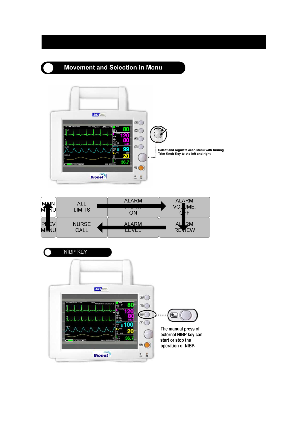
Select Menu Using by Trim Knob Key ....................................................................... 171
Select Arrow Item Menu ............................................................................................ 171
Letter Arrangement Menu ......................................................................................... 172
List selective menu ................................................................................................... 173
Operation Menu ........................................................................................................ 173
2. PATIENT/DATA MANAGEMENT ............................................................................... 174
2.1 Outline .................................................................................................................................... 175
2.2 Admit Type ............................................................................................................................. 175
2.3 Select Patient in Admit Information .................................................................................... 177
2.4 Alarm Outline ........................................................................................................................ 178
2.5 Alarm Setup ........................................................................................................................... 179
Rev. 2.61 6

BM3 User’s Manual
2.6 Alarm Limit ............................................................................................................................ 179
2.7 Alarm Print ............................................................................................................................ 180
2.8 Alarm Volume ........................................................................................................................ 180
2.9 Alarm Level ............................................................................................................................ 180
2.10 Nurse Call ............................................................................................................................. 181
2.11 Alarm Sound ........................................................................................................................ 182
3. SAVE RECORD ............................................................................................................. 183
3.1 Outline .................................................................................................................................... 184
3.2 Adjust to Record SAVE Mode .............................................................................................. 184
3.3 Measure with Monitor Mode ................................................................................................ 184
3.4 Measure with MANUAL Mode ............................................................................................ 185
3.5 Save ......................................................................................................................................... 185
3.6 Exit from Saving Mode ......................................................................................................... 186
4. SAVED DATA MANAGEMENT ................................................................................... 187
4.1 Record List View.................................................................................................................... 188
4.2 Exit from Record List............................................................................................................ 188
4.3 View Specified Patients Record List .................................................................................... 190
4.4 View All Patients Record List ............................................................................................... 190
4.5 Adjust Record ........................................................................................................................ 191
4.6 Delete a Record ...................................................................................................................... 192
4.7 Delete a Patients Record ....................................................................................................... 193
4.8 Delete All Patients Record .................................................................................................... 193
5. SETUP ............................................................................................................................ 194
5.1 SETUP .................................................................................................................................... 195
5.2. DISPLAY .............................................................................................................................. 195
5.3 SAVE MODE ......................................................................................................................... 196
5.4 USER SERVICE .................................................................................................................... 197
Rev. 2.61 7

BM3 User’s Manual
5.5 SYSTEM ................................................................................................................................. 197
5.6 KEY SOUND.......................................................................................................................... 198
5.7 MAKER SERVICE ............................................................................................................... 198
6. NIBP ............................................................................................................................... 199
6.1 Outline .................................................................................................................................... 200
6.2 NIBP Data Window ............................................................................................................... 201
6.3 NIBP Setup ............................................................................................................................. 202
ALARM LIMIT ........................................................................................................... 202
CUFF SIZE ............................................................................................................... 203
NIBP STAT ............................................................................................................... 203
INFLATION SET ....................................................................................................... 203
UNIT SELECT ........................................................................................................... 203
INTERVAL ................................................................................................................ 204
NIBP Status Messages ............................................................................................. 205
Erroneous NIBP measurement ................................................................................. 205
7. SpO2 ................................................................................................................................ 206
7.1 Outline .................................................................................................................................... 207
7.2 SpO2 Data Window ............................................................................................................... 208
7.3 SpO2 Setup ............................................................................................................................. 209
ALARM LIMIT ........................................................................................................... 209
SWEEP SPEED ........................................................................................................ 210
RATE VOLUME ........................................................................................................ 210
ALARM LEVEL ......................................................................................................... 210
PROBE OFF Condition ............................................................................................. 211
SPO2 Messages ....................................................................................................... 211
8. TEMPERATURE ........................................................................................................... 212
8.1 Outline .................................................................................................................................... 213
8.2 Temperature Data Window .................................................................................................. 214
8.3 Temperature Setup ................................................................................................................ 215
ALARM LIMIT ........................................................................................................... 215
UNIT SELECT ........................................................................................................... 215
Rev. 2.61 8

BM3 User’s Manual
PROBE SITE (Measurement Position) ...................................................................... 216
Check list .................................................................................................................. 216
TEMP Message ........................................................................................................ 216
9. PRINT ............................................................................................................................. 217
9.1 Print ........................................................................................................................................ 218
Print and Heat Sensitivity Paper ................................................................................ 218
Function and Setup Menu ......................................................................................... 219
9.2 Paper Change ......................................................................................................................... 221
10. TROUBLE SHOOTING .............................................................................................. 222
1. Noise in ECG ............................................................................................................................ 222
2. SpO2 malfunction .................................................................................................................... 223
3. Temp malfunction ................................................................................................................... 223
4. NIBP malfunction .................................................................................................................... 224
5. Abnormality in NIBP measurements ..................................................................................... 224
6. Failure in battery recharge ..................................................................................................... 225
7. Power failure ............................................................................................................................ 226
8. Periodic noises .......................................................................................................................... 227
9. Print failure .............................................................................................................................. 228
SPECIFICATION .............................................................................................................. 229
Ease of use ............................................................................................................... 230
Intended use ............................................................................................................. 230
Indication for use ....................................................................................................... 231
Additional Function ................................................................................................... 231
Monitor Environmental Specifications ....................................................................... 231
Power ....................................................................................................................... 231
Monitor Performance Specifications .......................................................................... 231
Graphical and Tabular Trends ................................................................................... 232
ECG capacity ............................................................................................................ 232
SpO2 capacity ........................................................................................................... 233
Respiration Performance Specifications .................................................................... 233
NIBP capacity ........................................................................................................... 233
Rev. 2.61 9

BM3 User’s Manual
Temperature Unit Performance Specifications .......................................................... 234
Accessories Included: ............................................................................................... 234
Option ....................................................................................................................... 234
Abbreviations and Symbols ................................................................................................ 235
PRODUCT WARRANTY ................................................................................................... 239
Rev. 2.61 10

1. BASIC
1.1 CE Standard Information
1.2 Read before Use
Warranty Period
Warning, Caution, Note
General Precaution on Environment
General Precaution on Electric Safety
Equipment Connection, Maintenance & Washing Equipment Connection
1.3
Product Components
Product Outline
Principal Characteristics of Product
Product Configuration and Option Product
Product Body Configuration
1.4
Function and Key
External Function
Operation Key
1.5
Standard Power Supply Application
1.6
Battery Power Supply Application
1.7
General Menu Operation
Screen Composition
Menu Selection
Menu Composition
Rev. 2.61 11

BM3 User’s Manual
1.1 CE Standard Information
Electromechanical safety standards met:
- EN 60601-1: 1990 + A1:1993 + A2: 1995 Medical Electrical Equipment, Part 1, General
Requirements for Safety.
- IEC/EN 60601-1-2 :2001 Electromagnetic compatibility -Requirements and tests.
- EN 1060-1:1995 Non-invasive sphygmomanometers - Part 1: General requirements
- EN 1060-3:1997 Non-invasive sphygmomanometers - Part 3: Supplementary requirements for
electro-mechanical blood pressure measuring systems
- EN ISO 9919:2005 Medical electrical equipment - Particular requirements for the basic safety and
essential performance of pulse oximeter equipment for medical use (ISO 9919:2005)
- EN 60601-2-27:2006 Medical electrical equipment - Part 2-27: Particular requirements for the
safety, including essential performance, of electrocardiographic monitoring equipment
- EN 60601-2-30:2000 Medical electrical equipment - Part 2-30: Particular requirements for the
safety, including essential performance, of automatic cycling non-invasive blood pressure monitoring
equipment
- EN 12470-4:2000 Clinical thermometers - Part 4: Performance of electrical thermometers for
continuous measurement
- EN 60601-2-49:2001 Medical electrical equipment - Part 2-49: Particular requirements for the
safety of multifunction patient monitoring equipment
Rev. 2.61 1.BASIC 12

BM3 User’s Manual
1.2 Read before Use
BIONET services are always available to you.
The followings are address and phone number for contacting information, services, and product
supplies.
How to Contact Us
Product Supply
Information
In the event of malfunction or failure, contact us along with the model name, serial number, and
※
product name of the equipment.
If you need the supply circuit diagram, component list, description and calibration
※
instruction etc. you can contact us we will provide you with it.
Bionet Co.,Ltd.
#1101 11F E&C Venture Dream Tower3 38-21, Digital-Ro, 31-Gil,
Guro-Gu, Seoul , REPUBLIC OF KOREA (ZIP 08376)
Overseas sales dept.
Tel:++82-2-6300-6418
Fax : ++82-2-6300-6454
E-mail : sales@ebionet.com
URL : http:// www.ebionet.com
The information in this manual only applies to BM3 patient monitor software version 1.10 .
Due to continuing product innovation, specifications in this manual are subject to change
without notice.
Rev. 2.61 1.BASIC 13

BM3 User’s Manual
Warranty Period
This product is manufactured and passed through strict quality control and through
inspection.
Compensation standard concerning repair, replacement, refund of the product complies
with “Consumer’s protection law” noticed by Korea Fair Trade Commission.
We provide a 1-year warranty period.(Two years in Europe)
We will repair or replace any part of the BM3 found to be defective in usual operating
circumstance for free to you.
This warranty does not apply to any defect caused by improper abuse, misuse or exposure to
poor management.
Rev. 2.61 1.BASIC 14

BM3 User’s Manual
Warning, Caution, Note
For special emphasis on agreement, terms are defined as listed below in user’s manual. Users
should operate the equipment according to all the warnings and cautions.
Warning
To inform that it may cause serious injury or death to the patient, property damage, material
losses against the “warning” sign
To inform that it may cause no harm in life but lead to injury against the “caution” sign
To inform that it is not dangerous but important “note” sign for proper installation, operation, and
maintenance of the equipment.
Caution
Note
Rev. 2.61 1.BASIC 15
BM3 User’s Manual
General Precaution on Environment
- Do not keep or operate the equipment in the environment listed below.
Avoid placing in an area
exposed to moist.
Do not touch the equipment
with wet hand.
Avoid placing in an area
where there is a high variation
of temperature.
Operating temperature
ranges from 10(C to
Avoid exposure to direct
sunlight
Avoid in the vicinity of
Electric heater
40(C. Operating humidity
ranges from 30% to 85%.
Avoid placing in an area where
there is an excessive
humidity rise or ventilation
Avoid placing in an area
where there is an
excessive shock or
problem.
Avoid placing in an area where
chemicals are
stored or where there is danger
of gas leakage.
Do not disjoint or disassemble
the equipment.
We take no responsibility for
it.
vibration.
Avoid being inserted
dust and especially
metal
material into the
equipment
Power off when the
equipment is not fully
installed.
Otherwise, equipment
could be damaged.
Rev. 2.61 1.BASIC 16

BM3 User’s Manual
CAUTIONS
Before Installation
Compatibility is critical to safe and effective use of this device. Please contact your local sales or
service representative prior to installation to verify equipment compatibility.
Defibrillator Precaution
Patient signal inputs labeled with the CF and BF symbols with paddles are protected against
damage resulting from defibrillation voltages. To ensure proper defibrillator protection, use only the
recommended cables and lead wires.
Proper placement of defibrillator paddles in relation to the electrodes is required to ensure
successful defibrillation.
Disposables
Disposable devices are intended for single use only. They should not be reused as performance
could degrade or contamination could occur.
Disposal of your old appliance
1. When this crossed out wheeled bin symbol is attached to a product it means
the product is covered by the European Directive 2002/96/EC.
2. All electrical and electronic products should be disposed of separately from
the municipal waste stream via designated collection facilities appointed by
the government or the local authorities.
3. The correct disposal of your old appliance will help prevent potential negative
consequences for the environment and human health.
4. For more detailed information about disposal of your old appliance, please
contact your city office, waste disposal service or the shop where you
purchased the product.
WARNING
This product contains a chemical known to the State of California to cause
cancer, birth defects, or other reproductive harm.
Rev. 2.61 1.BASIC 17

BM3 User’s Manual
Electrocute Precautions
To prevent skin burns, apply electrocute electrodes as far as possible from all other electrodes, a
distance of at 15 cm/6 in. is recommended.
EMC
Magnetic and electrical fields are capable of interfering with the proper performance of the device.
For this reason make sure that all external devices operated in the vicinity of the monitor comply with
the relevant EMC requirements. X-ray equipment or MRI devices are possible source of interference
as they may emit higher levels of electromagnetic radiation.
Also, keep cellular phones to other telecommunication equipment away from the monitor.
Rev. 2.61 1.BASIC 18

BM3 User’s Manual
CAUTIONS
Instruction for Use
For continued safe use of this equipment, it is necessary that the instructions are followed. However,
instructions listed in this in no way supersede established medical practices concerning patient care.
Loss of Data
Should the monitor at any time temporarily lose patient data, the potential exists that active
monitoring is not being done. Close patient observation or alternate monitoring devices should be
used until monitor function is restored.
If the monitor does not automatically resume operation within 60 seconds, power cycle the monitor
using the power on/off switch. Once monitoring is restored, you should verify correct monitoring
state and alarm function.
Maintenance
Regular preventive maintenance should be carried out annually (Technical inspections). You are
responsible for any requirements specific to your country.
MPSO
The use of a multiple portable socket outlet (MPSO) for a system will result in an enclosure leakage
current equal to the sum of all individual earth leakage currents of the system if there is an
interruption of the MPSO protective earth conductor. Do not use an additional extension cable with
the MPSO as it will increase the chance of the single protective earth conductor interruption.
Negligence
BIONET does not assume responsibility for damage to the equipment caused by improperly vented
cabinets, improper or faulty power, or insufficient wall strength to support equipment mounted on
such walls.
Rev. 2.61 1.BASIC 19

BM3 User’s Manual
NOTES
Power Requirements
Before connecting the device to the power line, check that the voltage and frequency. Ratings of the
power line are the same as those indicated on the unit’s label. If this is not the case, do not connect
the system to the power line until you adjust the unit to match the power source.
In U.S.A, if the installation of this equipment will use 240V rather than 120V, the source must
be a center-tapped, 240V, single-phase circuit.
Restricted Sale
U.S.A federal law restricts this device to sale by or on the order of a physician.
Supervised Use
This equipment is intended for use under the direct supervision of a licensed health care practitioner.
Ventilation Requirements
Set up the device in a location which affords sufficient ventilation. The ventilation openings of the
device must not be obstructed. The ambient conditions specified in the technical specifications must
be ensured at all times.
·Put the monitor in a location where you can easily see the screen and access the operating controls.
·This product is protected against the effects of cardiac defibrillator discharges to ensure proper
recovery, as required by test standards. (the screen may blank during a defibrillator discharge but
recovers within second as required by test standards.)
Reference Literature
Medical Device Directive 93/42/EEC
EN 60601-1/1990 +A1: 1993 +A2 : 1995 : Medical electrical equipment.
General requirements for safety
EN 60601-1-1/9. 1994 +A1 12.95: General requirements for safety.
Rev. 2.61 1.BASIC 20

BM3 User’s Manual
General Precaution on Electric Safety
Warning
BM3 OPERATION MANUAL
Check the item listed below before operating the equipment.
NOT
1. Be sure that AC power supply line is appropriate to use. (AC100 - 240V)
2. Be sure that the power source is the one supplied from Bionet. (DC18V, 2.8A , BPM050S18F02)
3. Be sure that the entire connection cable of the system is properly and firmly fixed.
4. Be sure that the equipment is completely grounded. (If not, there might be the problem occur in
the product.)
5. The equipment should not be placed in the vicinity of electric generator, X-ray, broadcasting
apparatus to eliminate the electric noise during operation. Otherwise, it may cause incorrect result.
Note
The Equipment should be placed far from generator, X-ray equipment, broadcasting equipment
or transmitting wires, so as to prevent the electrical noises from being generated during the
operation, When these devices are near the Equipment, it can produce inaccurate
measurements. For BM3, both independent circuit and stable grounding are essentially
required. In the event that the same power source is shared with other electronic equipment, it
can also produce inaccurate output.
Warning
Do not contacts with the patient while operate the machine It may cause serious danger to the
users. Use only the provided cable.
Warning
In case the Equipment does not operate as usual or damaged, do not use on patient, and
contact to the medical equipment technician of the hospital or the equipment supply division.
Rev. 2.61 1.BASIC 21

below. The customer or
system uses RF energy only for its internal
Therefore. Its RF emissions are very low and
are not likely to cause any interference in nearby
BM3 is classified as follows:
BM3 User’s Manual
Note
- BM3 classifies as Class
Equipment around combustible anesthetic or dissolvent.
- Noise level is B class regarding IEC/EN 60601-1 and the subject of Nose is B level concerning
IEC/EN60601-1-2.
I, BF &
CF concerning electric shock. It is not proper to operate this
Equipment Connection
Caution
For measurements in or near the heart we recommend connecting the monitor to the potential
equalization system. Use the green and yellow potential equalization cable and connect it to the
pin labeled with the symbol .
Manufacturer’s declaration - electromagnetic emission
The BM3 system is intended for use in the electromagnetic environment specified
the user of BM3 system should assure that it is used in such an environment
Emission test Compliance Electromagnetic environment - guidance
RF emissions
CISPR 11
RF emissions
CISPR 11
Harmonics emission
IEC 61000-3-2
Voltage fluctuation
IEC 61000-3-3
Group 1 The BM3
function.
electronic equipment
Class B The BM3 system is suitable for use in all establishm
ents other than domestic and those directly connect
A
Complies
ed to the public low-voltage power supplies building
s used for domestic purposes.
Rev. 2.61 1.BASIC 22

synthetic
Mains power quality should
Mains power quality should
commercial or
BM3 User’s Manual
Manufacturer’s declaration - electromagnetic immunity
The BM3 system is intended for use in the electromagnetic environment specified below.
The customer or the user of the BM3 system should assure that it is used in such an environment
Immunity test IEC 60601
Test level
Electrostatic disc
harge (ESD)
IEC 61000-4-2
Electrical fast
Transient / burst
IEC 61000-4-4
Surge
IEC 61000-4-5
Power frequency
(50/60Hz)
Magnetic field
6 kV Contact
8 kV Air
2kV for power supply lines
1kV for input/output lines
1 kV differential mode
2 kV common mode
3.0 A/m 3.0 A/m Power frequency magnetic fi
Compliance level Electromagnetic
Environment -guidance
6 kV Contact
8 kV Air
2kV for power supply line
s
1kV for input/output lines
1 kV differential mode
2 kV common mode
Floors should be wood, con
crete or ceramic tile. If floor
s are covered with
material, the relative humidit
y should be at least 30 %
be that of a typical commerc
ial or hospital environment.
be that of a typical commer
cial or hospital environment.
elds should be at levels cha
racteristic of a typical locatio
IEC 61000-4-8
Voltage dips, sh
ort
Interruptions and
Voltage variation
s
on power supply
input lines
IEC 61000-4-11
Note: Uт is the a.c. mains voltage prior to application of the test level.
<5% Uт (>95% dip in Uт)
for 0.5cycle
40% Uт (60% dip in Uт )
for 5 cycle
70% Uт (30% dip in Uт)
for 25 cycle
<5% Uт (<95% dip in Uт )
for 5 s
<5% Uт (>95% dip in Uт)
for 0.5cycle
40% Uт (60% dip in Uт )
for 5 cycle
70% Uт (30% dip in Uт)
for 25 cycle
<5% Uт (<95% dip in Uт
)
for 5 s
n in a typical
hospital environment.
Mains power quality should
be that of a typical commerc
ial or hospital environment. I
f th e u s er of the BM3
system requires continued op
eration during power mains i
nterruptions, it is recommend
ed that the BM3 system be p
owered from an uninterruptib
le power supply or a battery
Rev. 2.61 1.BASIC 23

quipment should be used no closer to any
separation distance
BM3 User’s Manual
The BM3 system is intended for use in the electromagnetic environment specified below.
The customer or the user of the BM3 system should assure that it is used in such an environment
Immunity test IEC 60601
Test level
Conducted RF
IEC 61000-4-6
3 Vrms
150 kHz to 80 MH
z
Compliance level Electromagnetic environment -guidance
3 Vrms
150 kHz to 80 MHz
Portable and mobile RF communications e
part of the BM3 system, including cables, t
han the recommended
calculated from the equation applicable to t
he frequency of the transmitter.
Recommended separation distance
Rev. 2.61 1.BASIC 24

Field strengths from fixed RF transmitters,
mined by an electromagnetic site
BM3 User’s Manual
Radiated RF
IEC 61000-4-3
3 V/m
80.0 MHz to 2.5 G
Hz
3 V/m
80.0 MHz to 2.5 G
Hz
Recommended separation distance
Where P is the maximum output power rat
ing of the transmitter in watts (W) accordin
g to the transmitter manufacturer and d is
the recommended separation distance in m
eters (m).
as detersurvey,
(a) Should be less than the compliance lev
el in each frequency range (b).
Interference may occur in the vicinity of
equipment marked with the following symb
ol:
Note 1) Uт is the A.C. mains voltage prior to application of the test level.
Note 2) At 80 MHz and 800 MHz, the higher frequency range applies.
Note 3) These guidelines may not apply in all situations. Electromagnetic propagation is affected by a
bsorption and reflection from structures, objects and people.
Rev. 2.61 1.BASIC 25

Field strengths from fixed transmitters, such as base stations for radio (cellular/cordless) telephones
normal operation. If abnormal performance is observed, additional measures may be
in which radiated RF disturbances
system can help prevent electromagnetic interference by maintaining a
mended below, according to the maximum output power of the communications
BM3 User’s Manual
a
and land mobile radios, amateur radio, AM and FM radio broadcast and TV broadcast cannot be pred
icted theoretically with accuracy. To assess the electromagnetic environment due to fixed RF transmitt
ers, an electromagnetic site survey should be considered. If the measured field strength in the locatio
n in which the EUT is used exceeds the applicable RF compliance level above, the EUT should be o
bserved to verify
necessary, such as re-orienting or relocating the EUT.
b Over the frequency range 150 kHz to 80 MHz, field strengths should be less than [V1] V / m.
Recommended Separation Distances Between Portable and Mobile RF Communications Equipment and th
e BM3 system.
The BM3 system is intended for use in an electromagnetic environment
are controlled. The user of the BM3
minimum distance between portable and mobile RF communications equipment (transmitters) and the BM3
system as recom
equipment.
Rated maximum output
power (W) of transmitter
0.01 0.12 0.12 0.23
0.1 0.37 0.37 0.74
1 1.17 1.17 2.33
10 3.70 3.70 7.37
100 11.70 11.70 23.30
For transmitters rated at a maximum output power not listed above, the recommended separation dist
ance (d) in meters (m) can be estimated using the equation applicable to the frequency of the transm
itter, where P is the maximum output power rating of the transmitter in watts (W) according to the tra
nsmitter manufacturer.
Note 1: At 80 MHz and 800 MHz, the separation distance for the higher frequency range applies
Separation distance (m) according to frequency of transmitter
150 kHz to 80 MHz 80 MHz to 800 MHz 800 MHz to 2.5 GHz
Note 2: These guidelines may not apply in all situations. Electromagnetic propagation is affected by a
bsorption and reflection from structures, objects, and people.
Rev. 2.61 1.BASIC 26

enters
electromagnetic site survey, should
BM3 User’s Manual
Immunity and Compliance Level
Immunity test IEC 60601 Test Level Actual Immunity Level Compliance Level
Conducted RF
IEC 61000-4-6
Radiated RF
IEC 61000-4-3
3 Vrms, 150 kHz to 80
MHz
3 V/m, 80 MHz to 2.5
GHz
3 Vrms, 150 kHz to 80
MHz
3 V/m, 80 MHz to 2.5
GHz
3 Vrms, 150 kHz to 80
MHz
3 V/m, 80 MHz to 2.5
GHz
Guidance and manufacturer’s declaration - electromagnetic immunity
The BM3 system is intended for use in the electromagnetic environment specified below.
The customer or the user of the BM3 system should assure that it is used in such an environment
Immunity test IEC 60601
Test level
Conducted RF
IEC 61000-4-6
3 Vrms
150 kHz to 80MH
z
Compliance level Electromagnetic environment -guidance
3 Vrms
150 kHz to 80 MHz
BM3 system must be used only in a shield
ed location with a minimum RF shielding ef
fectiveness and, for each cable that
the shielded location with a minimum RF s
hielding effectiveness and, for each cable t
Radiated RF
IEC 61000-4-3
3 V/m
80.0 MHz to 2.5 G
Hz
3 V/m
80.0 MHz to 2.5 G
Hz
hat enters the shielded location
Field strengths outside the shielded locatio
n from fixed RF transmitters, as determine
d by an
be less than 3V/m.a
Interference may occur in the vicinity of eq
uipment marked with the following symbol:
Rev. 2.61 1.BASIC 27

BM3 User’s Manual
Note 1) These guidelines may not apply in all situations. Electromagnetic propagation is affected by a
bsorption and reflection from structures, objects and people.
Note 2) It is essential that the actual shielding effectiveness and filter attenuation of the shielded loc
ation be verified to assure that they meet the minimum specification.
a- Field strengths from fixed transmitters, such as base stations for radio (cellular/cordless) telephone
s and land mobile radios, amateur radio, AM and FM radio broadcast and TV broadcast cannot be pr
edicted theoretically with accuracy. To assess the electromagnetic environment due to fixed RF trans
mitters, an electromagnetic site survey should be considered. If the measured field strength outside th
e shielded location in which the EUT is used exceeds 3V/m, the EUT should be observed to verify n
ormal operation.
If abnormal performance is observed, additional measures may be necessary, such as relocating the
EUT or using a shielded location with a higher RF shielding effectiveness and filter attenuation.
Note
For Type A Professional ME Equipment intended for use in domestic establishment instructions
for use includes a warning:
This ME equipment is intended for use by professional healthcare personnel only.
Biocompatibility
When used as intended, the parts of the product described in this operator manual, including
accessories that come in contact with the patient during the intended use, fulfill the biocompatibility
requirements of the applicable standards. If you have questions about this matter, please contact
BIONET or its representatives.
Maintenance and Washing Equipment Connection
Using various methods can clean BM3 and its accessories. Please follow the methods mentioned
below to avoid unnecessary damage or contamination to the Equipment.
We do not repair with free of charge regardless of warranty period if it is contaminated or damaged
with using dangerous material not designated for washing.
Rev. 2.61 1.BASIC 28

BM3 User’s Manual
Cleaning Applied Parts
Do not permit any liquid to enter the monitor case and avoid pouring it on the monitor while
cleaning. Do not allow water or cleaning solution to enter the connectors of jack cover.
Recommended cleaning agents:
Alcohol (Ethanol 70%, Iosopropanol 70%, Window cleaner)
Ammonias (Dilution of ammonia <3%, Window cleaner)
Tensides (dishwasher detergents) (Edisonite schnellreiniger®, Alconox® )
Cables and Leadwires
CAUTION
Do not use acetone or ketone solvents for cleaning; do not use an autoclave or steam cleaner.
Cables and leadwires can be cleaned with a warm, damp cloth and mild soap, or isopropyl alcohol
wipes. For more intensive disinfecting (near sterile) Ethylene Oxide (ETO) is acceptable but will
reduce the useful lifetime of the cable or leadwire.
CAUTION
The decision to sterilize must be made per your institution’s requirements with an awareness of
the effect on the integrity of the cable or leadwire.
Note
The Equipment needs safety inspection once a year. Please refer to user’s guide or service
manual for the examine objects.
Please check carefully both frame and sensor, after cleaning the Equipment, Do not use the
equipment that is worn out or damaged.
At least once a month, clean and wipe off the frame by using the soft cloth after wetting it with water
and alcohol. Do not use lacquer, thinner, ethylene, and oxidizer which may leads damage to the
equipment.
Rev. 2.61 1.BASIC 29

BM3 User’s Manual
Make sure both cables and accessories are free of dust or contaminants, and wipe them off with soft
cloth wetted with warm water (40°), and at least once a week, clean them by using the clinical
alcohol.
Do not submerge the accessories under any liquid or detergent. Also, make sure any liquid not to
penetrate into the Equipment or probe.
Disinfecting
Do not mix disinfecting solutions (such as bleach and ammonia) as hazardous gases may result.
Clean equipment before disinfecting.
Recommended disinfecting agents:
Aldehyde based (Cidex® activated dialdehyde solution, Gigasept )
Alcohol base (Ethanol 70%, Isopropanol 70%, Spitacid®, Streilium fluid®, Cutasept®, Hospisept®,
Tinktur forte, Sagrosept®, Kodan
®
)
Caution
Do not dispose single use probe to any hazard place, Always think about environmental
contamination.
Caution
There is back-up battery on board inside system. When users dispose this battery, Please
waste proper place for environmental protection.
Warning
Check the electrodes of batteries before changing them.
· Operate BM3 with internal electric power supply when unsure of external ground connection or
installation occur.
· Remove the 1st Battery when not using equipment for a while without any damage.
For other applied parts such as temperature sensors, pulse oximetry probes, and NBP cuffs, you
must consult the manufacturer for cleaning, sterilization, or disinfecting methods.
Rev. 2.61 1.BASIC 30

BM3 User’s Manual
1.3 Product Components
BM3 OPERATION MANUAL
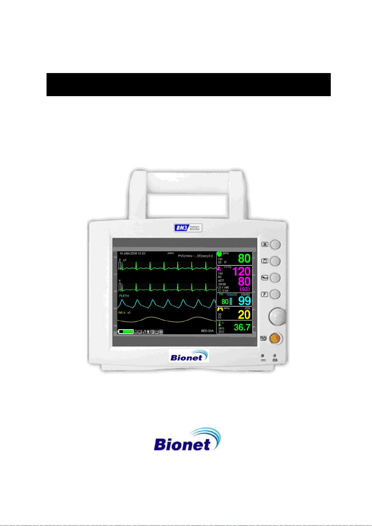
Product Outline
BM3 monitor is a product used for monitoring biological information and occurrence of a patient.
Main function ns of the product include displaying information such as ECG, respiration, SpO2, NIBP
and temperature on its LCD screen and monitoring parameter, and alarming. It also prints out waves
and parameters via a printer.
Principal Characters of Product
BM3 is a small-size multifunctional monitoring equipment for a patient designed to an easy usage
during movement. It features devices for DC power supply ( DC 18V, BPM050S18F02) as well as
installing its handle to the patient’s bed. The equipment also measures major parameters such as
ECG, SpO2, NIBP, temperature and pulse, displaying it on a 7-inch color LCD screen. It also
enables users to check waves and parameters and other vital signs of a patient via the 58mm
thermal printer and monitor the patient by the remote-controlled alarm system. It also enables to
build a central monitoring system by linking devices used for separate patients so that one can
monitor several patients at a time.
Warning
You may have distortion or signal noise when you use nonstandard or other brand's
accessories.
We strongly recommend you use only the authorized accessories which we supply.
Warning
BEFORE USE — Before putting the system into operation visually inspect all connecting cables
for signs of damage. Damaged cables and connectors must be replaced immediately.
Before using the system, the operator must verify that it is in correct working order and
operating condition. Periodically, and whenever the integrity of the product is in doubt, test all
functions.
Rev. 2.61 1.BASIC 31

BM3 User’s Manual
Product Configuration
1. Main body of BM3 Monitor 1 EA
2. 3-Lead Patient Cable 1EA
3. Disposable electrodes 10 EA
4. NIBP extension hose (3M long) 1EA
5. Adult cuff (25-35 Cm) 1EA
6. SpO2 extension cable (2M) 1EA
7. Reusable Adult SpO2 Probe 1 EA
8. DC Adaptor (BPM050S18F02 made in Bridge power Co., Ltd.) 1 EA
Option Product
1. Temperature
2. Thermal printer and Thermal Paper
Warning
In order to avoid electrical shock, do not open the cover. Disassembling of the
equipment should be done only by the service personnel authorized by BIONET
Warning
Users must pay attention on connection any auxiliary device via LAN port or nurse
calling. Always consider about summation of leakage current, please check if the
auxiliary device is qualified by IEC 60601-1, or consult your hospital biomedical engineer.
Rev. 2.61 1.BASIC 32
Product Body Configuration
BM3 User’s Manual
Rev. 2.61 1.BASIC 33
BM3 User’s Manual
Rev. 2.61 1.BASIC 34

BM3 User’s Manual
ECG Measuring
Connector
NIBP Measuring
Connector
Temp. Measuring
Connector
SpO2 Measuring
Connector
Rev. 2.61 1.BASIC 35
BM3 User’s Manual
Rev. 2.61 1.BASIC 36

Accessories
ECG Cable +
Extension Cable
SpO2 Cable +
Extension Cable
BM3 User’s Manual
NIBP Cuff+
Extension cable
Temperature
sensor (Option)
Rev. 2.61 1.BASIC 37
Equipment Sign
BM3 User’s Manual
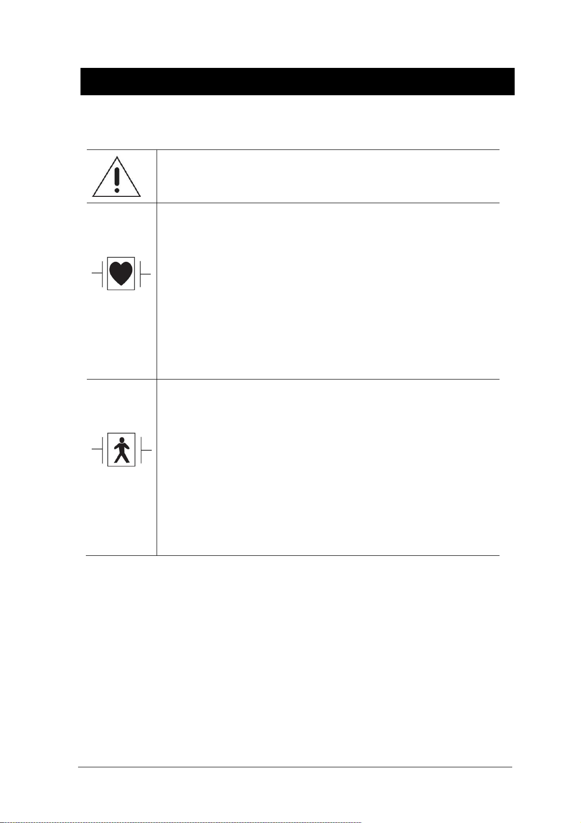
ATTENTION :
Consult accompanying documents
Defibrillator-proof type CF applied part :
Insulated (floating) applied part suitable for intentional external and internal
application to the patient including direct cardiac application. "Paddles"
outside the box indicate the applied part is defibrillator proof.
Medical Standard Definition :
F-type applied part(floating/insulated) complying with the specified
requirements of IEC 60601-1/UL 2601-1/CSA 601.1
Medical Standards to provide a higher degree of protection against electric
shock tan that provided by type BF applied parts.
Defibrillator-proof type BF applied part :
Insulated (floating) applied part suitable for intentional external and internal
application to the patient excluding direct cardiac application. "Paddles"
outside the box indicate the applied part is defibrillator proof.
Medical Standard Definition :
F-type applied part (floating/insulated) complying with the specified
requirements of IEC 60601-1/UL 2601-1/CSA 601.1
Medical Standards to provide a higher degree of protection against electric
shock than that provided by type B applied parts.
Rev. 2.61 1.BASIC 38
BM3 User’s Manual
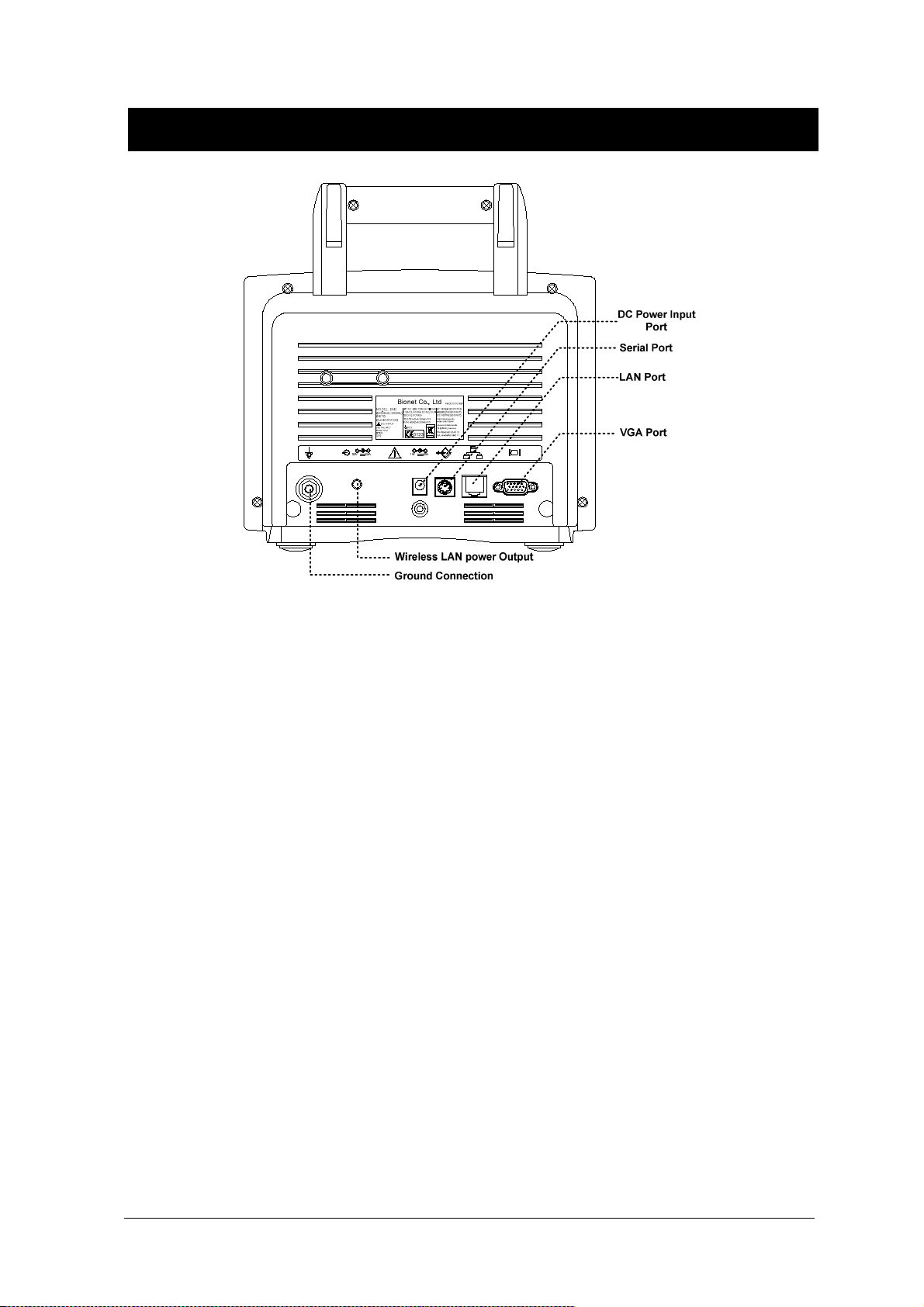
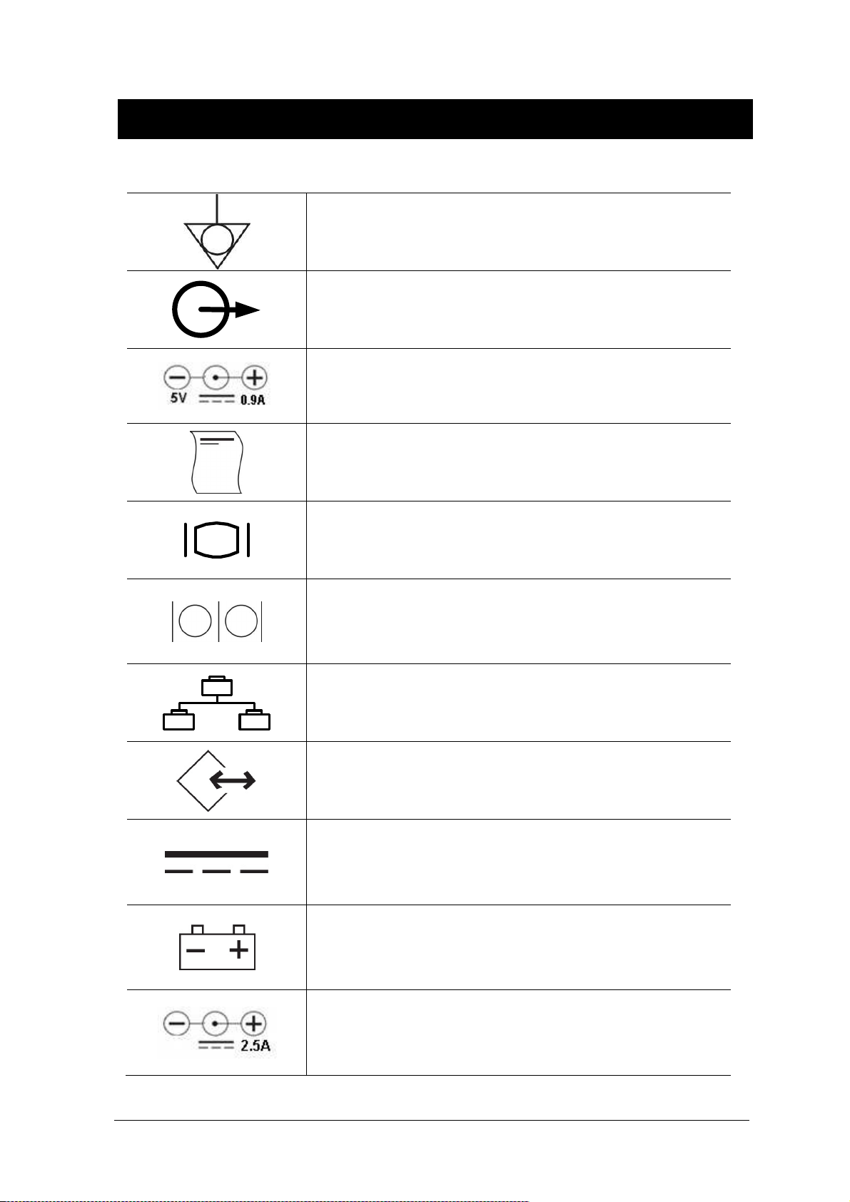
Ground
Output port
DC Power Output
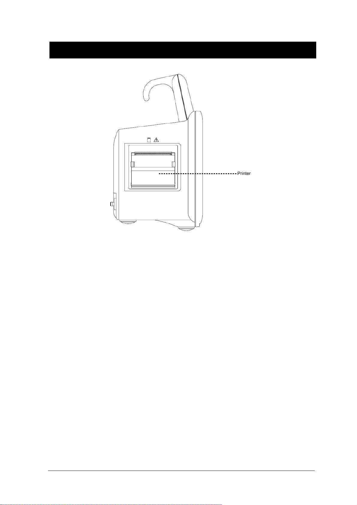
Printer
VGA Output
Serial Port
LAN Port
AUX Connector Port
DC Input Indicator
Battery Operation Indicator
18V
Rev. 2.61 1.BASIC 39
DC Power Input port
BM3 User’s Manual
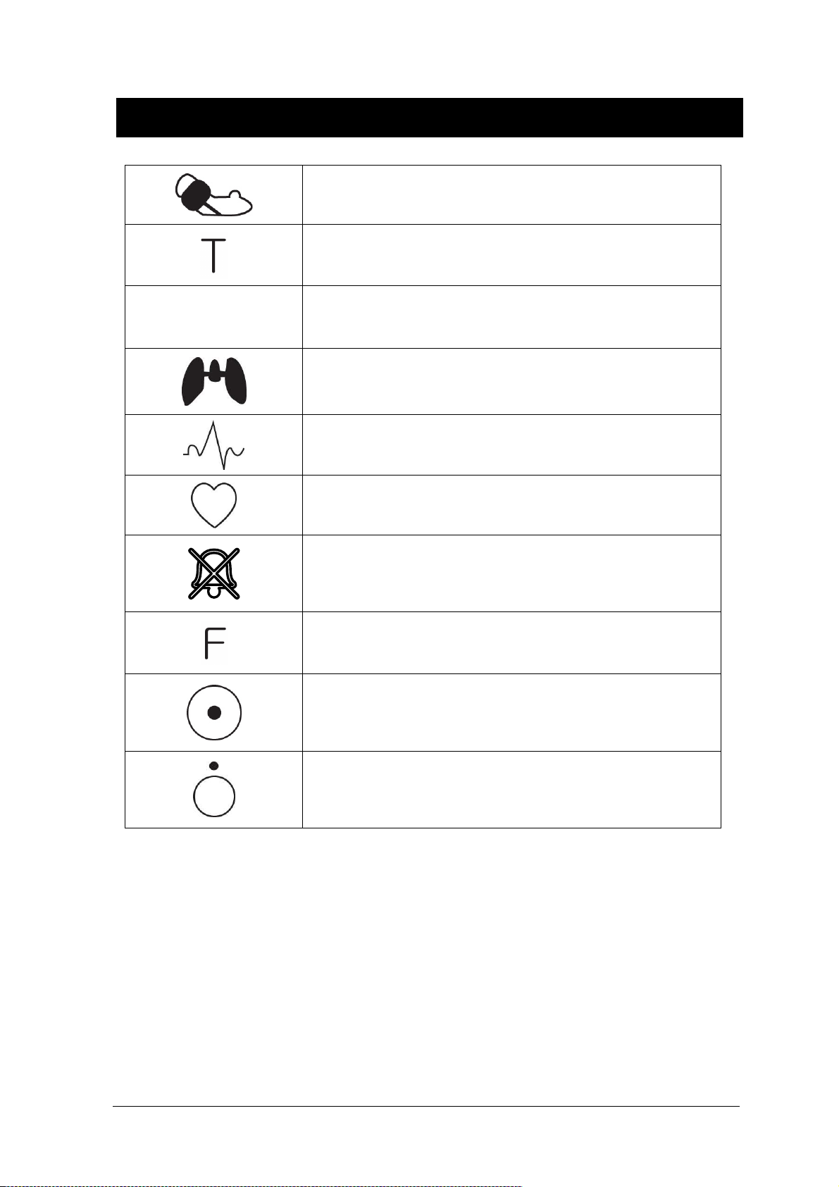
NIBP
Temperature
PR
Pulse Rate
Respiration
ECG
Heart Pulse
Alarm Off
Function
Power On
Power Off
Rev. 2.61 1.BASIC 40

BM3 User’s Manual
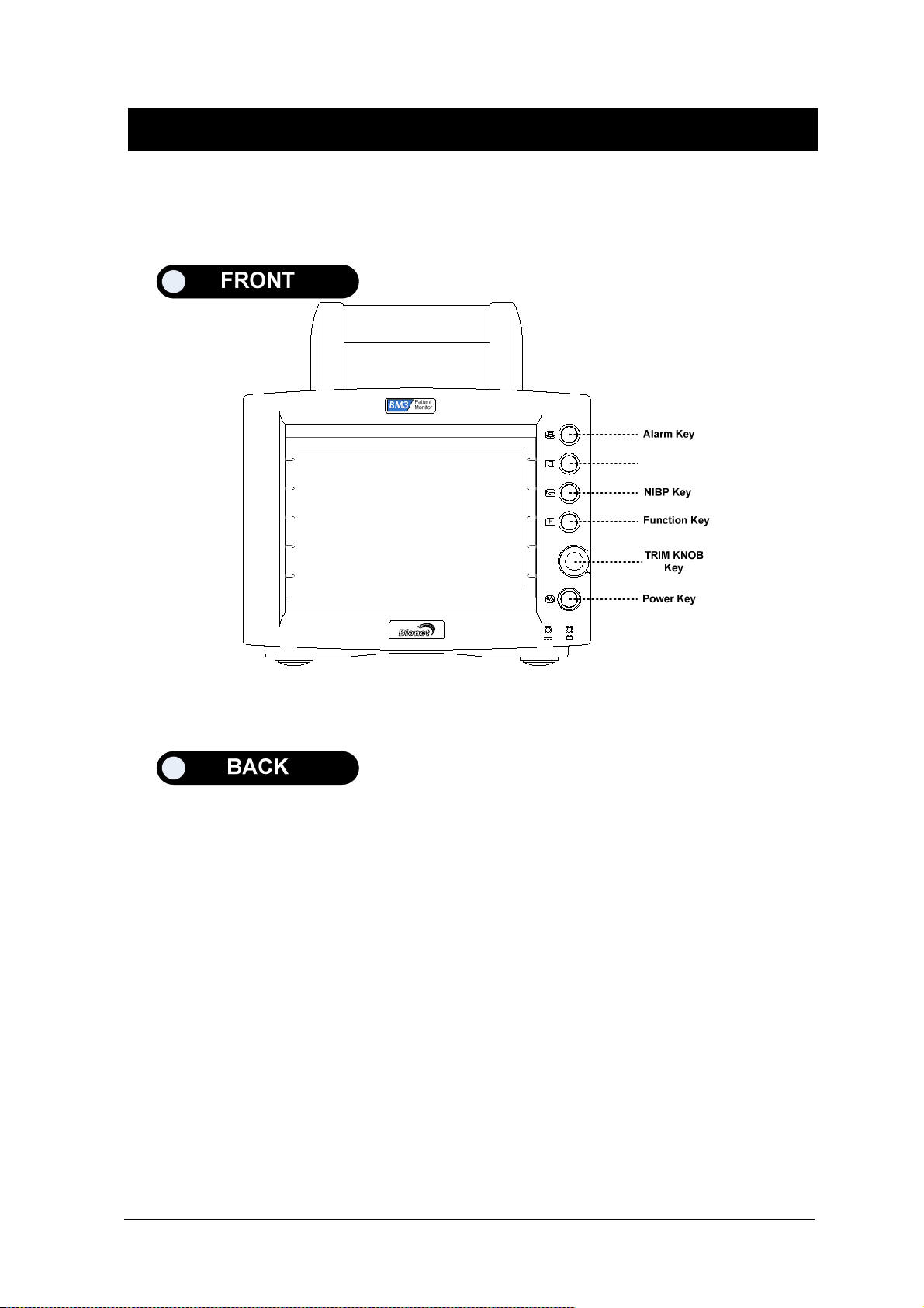
1.4 Function and Key
External Function
The front panel of this product consists of an LCD screen and five function keys and one trim knob.
Parameter windows
Alarm
Printer
Measure Blood Pressure
Function
Trim Knob
Power ON/OFF
Battery Power LED
Screen
DC Power LED
Operation Key
1. Power : Switches on and off the Power.
2. Function Key
3. Blood Pressure:Manually completes measuring blood pressure.
4. Printer:Prints out the waves selected from the menu until the key is pressed to stop.
5. Alarm: Stop alarm sound.
First press stops the current alarm for one minute
Second press stops the all alarm for two minutes.
Third press stops the all alarm off.
Fourth press makes the alarm back to the original setting.
6. Trim Knob:This key is used to select menu by turning it clock or anticlockwise to move cursors.
Rev. 2.61 1.BASIC 41
BM3 User’s Manual
Rev. 2.61 1.BASIC 42

BM3 User’s Manual
1.5 Standard Power Supply Application
DC Power
DC Power LED is lighted on when the DC Power is plugged into the inlet at the back of the product.
A press of power key makes the machine ready for use.
Warning
This equipment must only be connected to a supply mains with protected earth.
Rev. 2.61 1.BASIC 43

BM3 User’s Manual
1.6 Battery Power Supply Application
Battery power can be supplied for enabling a portable use or a use during DC power failure.
Operation
1. Battery Power LED is lighted on when the machine is in use.
2. The DC/battery power is only sustainable for 1 hour.
3. Battery is automatically charged when the machine is connected to DC Power Supply. Battery
LED is lighted on after blinking.
4. The charging status of the batteries is displayed with 5 green boxes, each indicating a different
charging
. ( 0% -> 25% -> 50% -> 75% -> 100%)
Battery code: ICR18605 22F-031PpTC (10.8V - 2200mA, Li-ion)
The Lithium-Ion battery is a rechargeable battery containing Lithium-Ion cells. Each battery contains
an integrated electronic fuel gauge and a safety protection circuit.
Rev. 2.61 1.BASIC 44

BM3 User’s Manual
5. The discharge condition of battery is indicated with on of 5 yellow boxes, each box showing a
different level of charge available.
(100% -> 75% -> 50% -> 25% -> 0%)
When remained battery is less than 25%, the battery icon box is turned to red one with blink.
The device will be turned off automatically after 5 minutes from that warning sign. In case of that
warning sign with red and blink at icon box, charge the device immediately with DC power
adaptor which is provided from BIONET.
-Battery charging time: More than 6 hours
-Continuous battery use time: Lowest 1 hour to highest 2 hours continuous use (buffering)
Warning
Check the electrodes of batteries before charging them.
6. Battery status indication: When battery is apart from equipment and out of order, it is shown by a
red `X' as shown below.
7. Low power supply: When you use the power of less than 16V, the battery indication disappears
and the ”LOW” indication is active.
Display of Low power supply
Note
Battery is not charged when the LOW power is used.
Rev. 2.61 1.BASIC 45

BM3 User’s Manual
The Impact of Lithium-Ion Battery Technology on the Battery
The following are the key points you should know about Lithium-Ion battery technology:
The battery will discharge on its own, even when it is not installed in a monitor. This discharge is the
result of the Lithium-Ion cells and the bias current required for the integrated electronics.
By the nature of Lithium-Ion cells, the battery will self-discharge.
The self-discharge rate doubles for every 10°C (18°F) rise in temperature.
The capacity loss of the battery degrades significantly at higher temperatures.
As the battery ages, the full-charge capacity of the battery will degrade and be permanently lost. As
a result, the amount of charge that is stored and available for use is reduced.
Conditioning Guideline
the battery in the monitor full charged and discharged every six months and condition it using the
battery charger.
Storage Guideline
Store the battery outside of the monitor at a temperature between 20°C to 25°C (68°F to 77°F).
When the battery is stored inside a monitor that is powered by an AC power source, the battery cell
temperature increases by 15°C to 20°C (59°F to 68°F) above the room’s ambient temperature. This
reduces the life of the battery.
When the battery is stored inside a monitor that is continuously powered by an AC power source
and is not powered by battery on a regular basis, the life of the battery may be less than 12 months.
BIONET recommends that you remove the battery and store it near the monitor until it is needed for
transport.
How to Recycle the Battery
When the battery no longer holds a charge, it should be replaced. The battery is recyclables.
Remove the old battery from the monitor and follow your local recycling guidelines.
WARNING
EXPLOSION HAZARD —
DO NOT incinerate the battery or store at high temperatures. Serious injury or death could
result.
Rev. 2.61 1.BASIC 46
BM3 User’s Manual
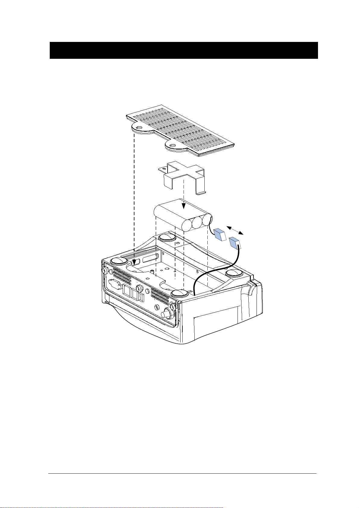
To insert and remove the battery pack.
Assembly or replacement, as shown in the figure below.
Rev. 2.61 1.BASIC 47

BM3 User’s Manual
1.7 DISPLAY MODE ( MONITOR OR SPOT )
You can selected display mode in user service ( Monitoring and Spot).
MONITOR : Refer to the Monitor chapter of this manual for details.
SPOT : Refer to the SPOT chapter of this manual for details.
Rev. 2.61 1.BASIC 48

MONITORING MODE
1. General Operation
2. Patient/Data Management
3. Setup
4. Trend
5. ECG
6. SpO2
7. Respiration
8. NIBP
9. Temperature
10. PRINT
11. Message List
12. Default Setting Value
Rev. 2.61 49

BM3 User’s Manual
1. General Operation
1.1 General Manu Operation
Screen Composition
10- JA N- 2 007 12: 2 3
x 2
II
II
PL ETH
Real Time Wave
Window
John
PVC ( 0 / mi n ): 0 ,
PVC 99/ m i n
ST(m m ): 0. 0
100
50
150
60
A DT
09: 3 0
1 HR
0:5 4
PR
Parameter
Windows
B PM
P
m m Hg
%Sp O2
100/ 9 0
MMMMMMMMMMM
MMMMMMMMMMM
II
MMMMMMMMMMM
RR I I
Pr e v
ADMIT
TYPE :
ADT
HEIGHT
Me n u 4 Me n y u 5 Men u 6
UNIT:
CM
CHANGE
Men u 2 Men u 3
ADMIT
INFO
WEIGHT
UNIT:
KG
DISCHARGE
DEFAULT
SETTING
Ve r . 4. 00B HCDD C
X1
30
10
37. 0
35. 0
Menu Select Window
Real Time Wave Window:Displays measured results by up to three waves.
Menu Select Window:Menus appear when they are activated..
Parameter Window:Measured and setup data are displayed in five windows.
RPM
‘
C
30S
Rev. 2.61 1. General Operation 50
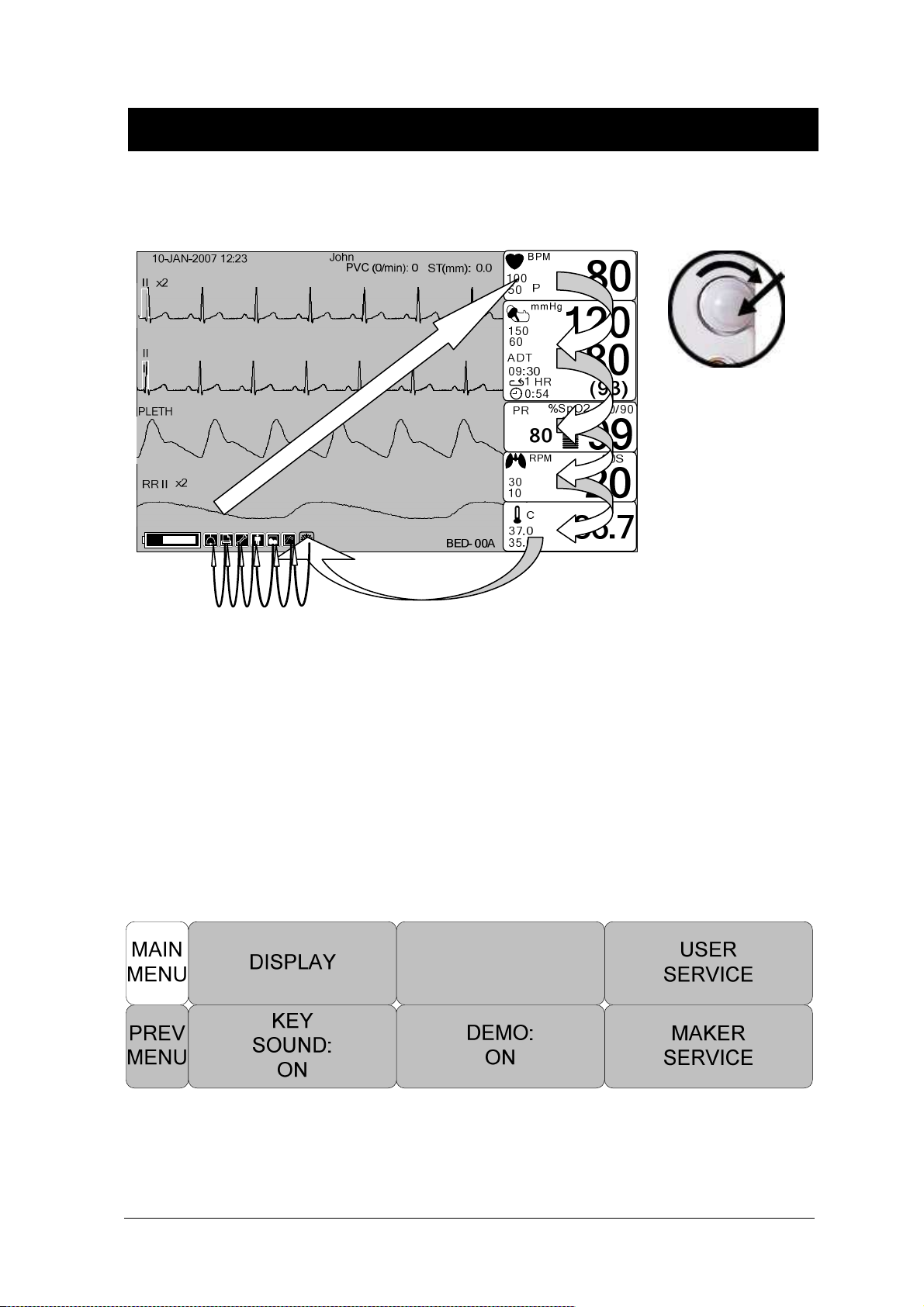
Menu Selection
BM3 User’s Manual
Turn or press the knob.
When the Trim Knob Key is turned, menus are selected in the order indicated above. The above
screen shows that the MORE menus is selected. The menus move to the right in the order of MORE
MENU → ECG → NIBP →SpO2 → RESP → TEMP. An inactivated window is jumped off.
Menu Composition
More Menu Window
When the additional menu is selected it will set and cancel the functions.
Rev. 2.61 1. General Operation 51

BM3 User’s Manual
Numerical value sign widow
This window displays a measured parameter, function setup, and the boundary of parameter values.
Alarm limit
value
Menu selection by using Trim Knob key
As the key is turn to the right, the menu selection moves clockwise. As the key is turn to the left, the
menu selection moves counterclockwise. The menu selection is activated when you depress Trim
Knob key.
30
10
RPM
30S
Breathing
20
Menu selection with arrows
Upward Movement: Turns the Trim Knob key to the left.
Downward Movement: Turns the Trim Knob key to the right.
Selection is made by pressing the Trim Knob key. One comes out of the menu after the selection.
Rev. 2.61 1. General Operation 52
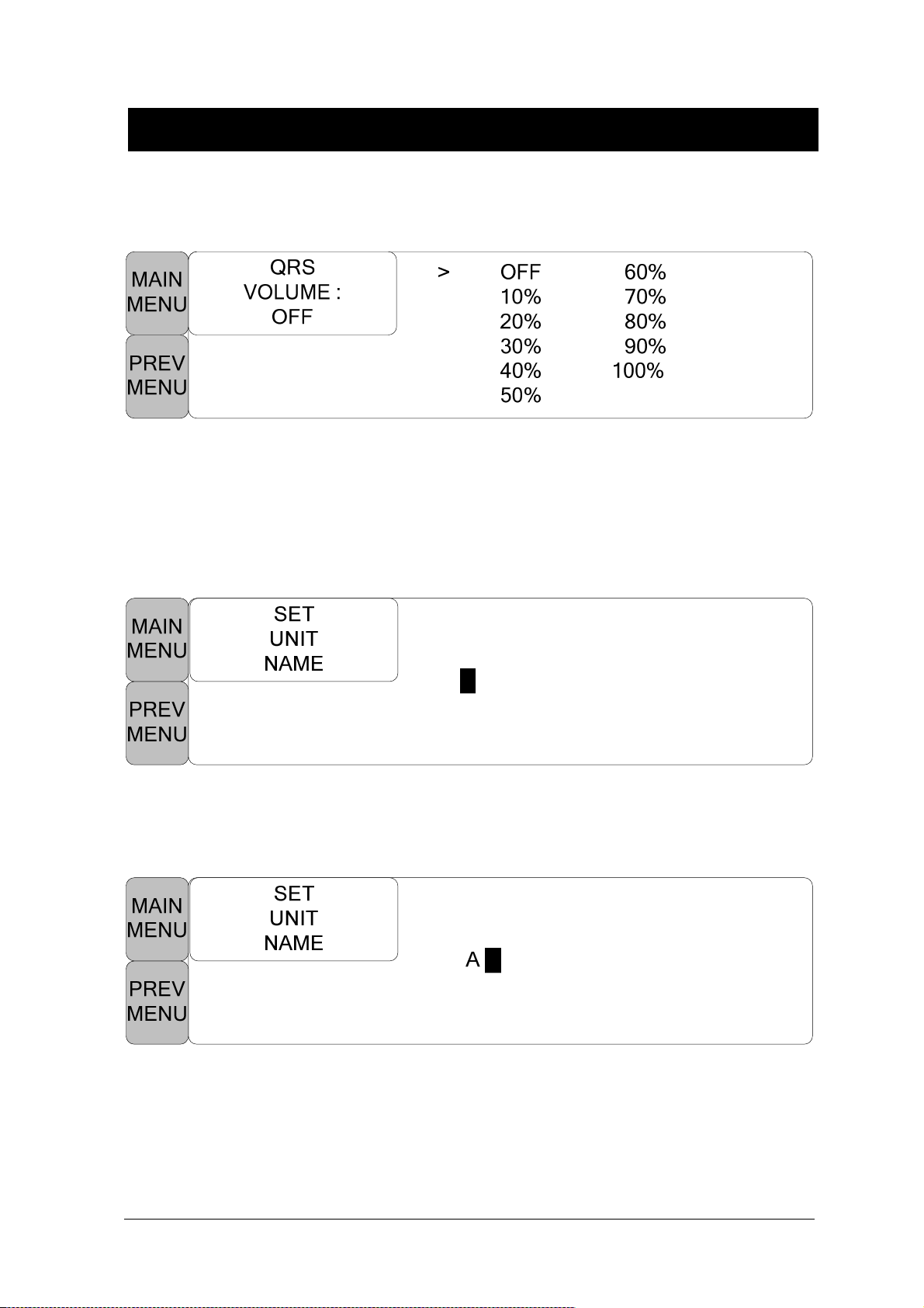
BM3 User’s Manual
When moving the within quadrilateral, the letter reverses, and the numeric value reflects
immediately.
Word feature menu
The following figure shows the screen where the word sequence menu is activated within the word
sequence correction menu. Here, the cursor moves over the words when the Trim Knob key is
turned in the clockwise direction.
The above figure shows how the cursor moves on the screen. The cursor moves according to the
direction the Trim Knob Key is turned. Press the Trim Knob key if you want to change a letter
currently on the screen.
The above figure shows how the cursor is selected to change a letter. Right-hand turning of the Trim
Knob Key makes it possible to select in the order of 0-9,A-Z, and a blank, while left-hand turning
makes the movement in the opposite direction. Once a letter or a number is selected, the screen
comes back to the condition where the same process of selection can be made. One may move to
Rev. 2.61 1. General Operation 53
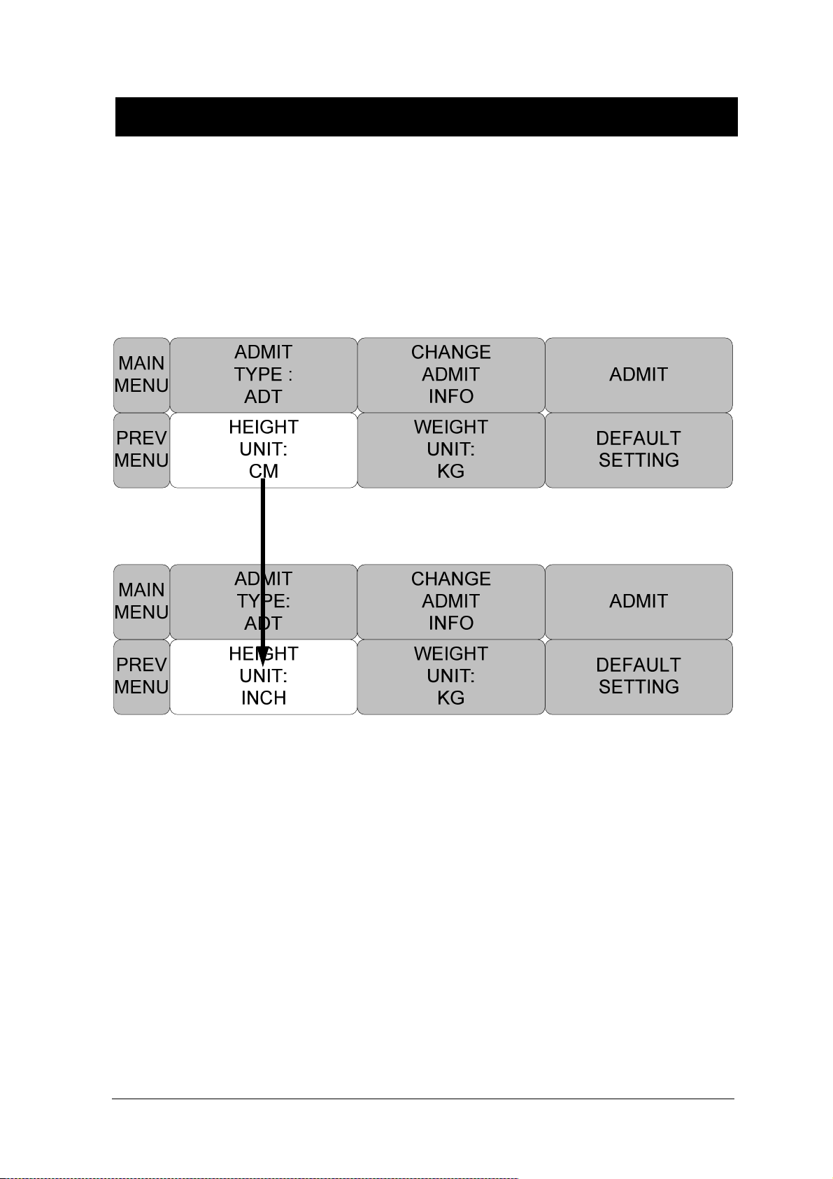
BM3 User’s Manual
the menu item in the left of the screen to end the process, which is completed by pressing Trim
Knob Key. After completion, the screen comes back to the earlier picture.
Operation menu
The setup value changes without a selection when the menu is moved.
Rev. 2.61 1. General Operation 54

2. PATIENT/DATA MANAGEMENT
2.1 ADMIT
ADMIT TYPE
CHANGE ADMIT INFO
DISCHARGE
ADMIT
HEIGHT
WEIGHT
DEFAULT SETTING
2.2 ALARM
ALL LIMITS
ALARM PRINT
ALARM VOLUME
PARAMETER LEVEL
ARRHYTH LEVEL
ALARM REVIEW
ALARM LIST
SAVE CONDITION
NURSE CALL
Rev. 2.61 55

2.1 ADMIT
BM3 User’s Manual
ADMIT TYPE :
CHANGE ADMIT INFO :
information pertinent to the monitored patient.
ADMIT:
Depending on how your monitor is set up, you will see either ADMIT patient or new case
DISCHARGE:
patient.
HEIGHT, WEIGHT UNIT :
Set the exercise environment of equipment in discharge status.
The CHANGE ADMIT INFO option allows you to change or enter
This menu option indicates that patient is admitted. You select it to discharge the
these options change the units of measure for height and weight.
DEFAULT SETTING : Configure alarms, set alarm limits, and establish display defaults to
be recalled whenever a discharge is performed.
ADMIT TYPE
Set the exercise environment of equipment in discharge status.
ADU : ADULT // PED: PEDIATRIC // NEO : NEONATE
Rev. 2.61 2. PATIENT/DATA MANAGEMENT 56
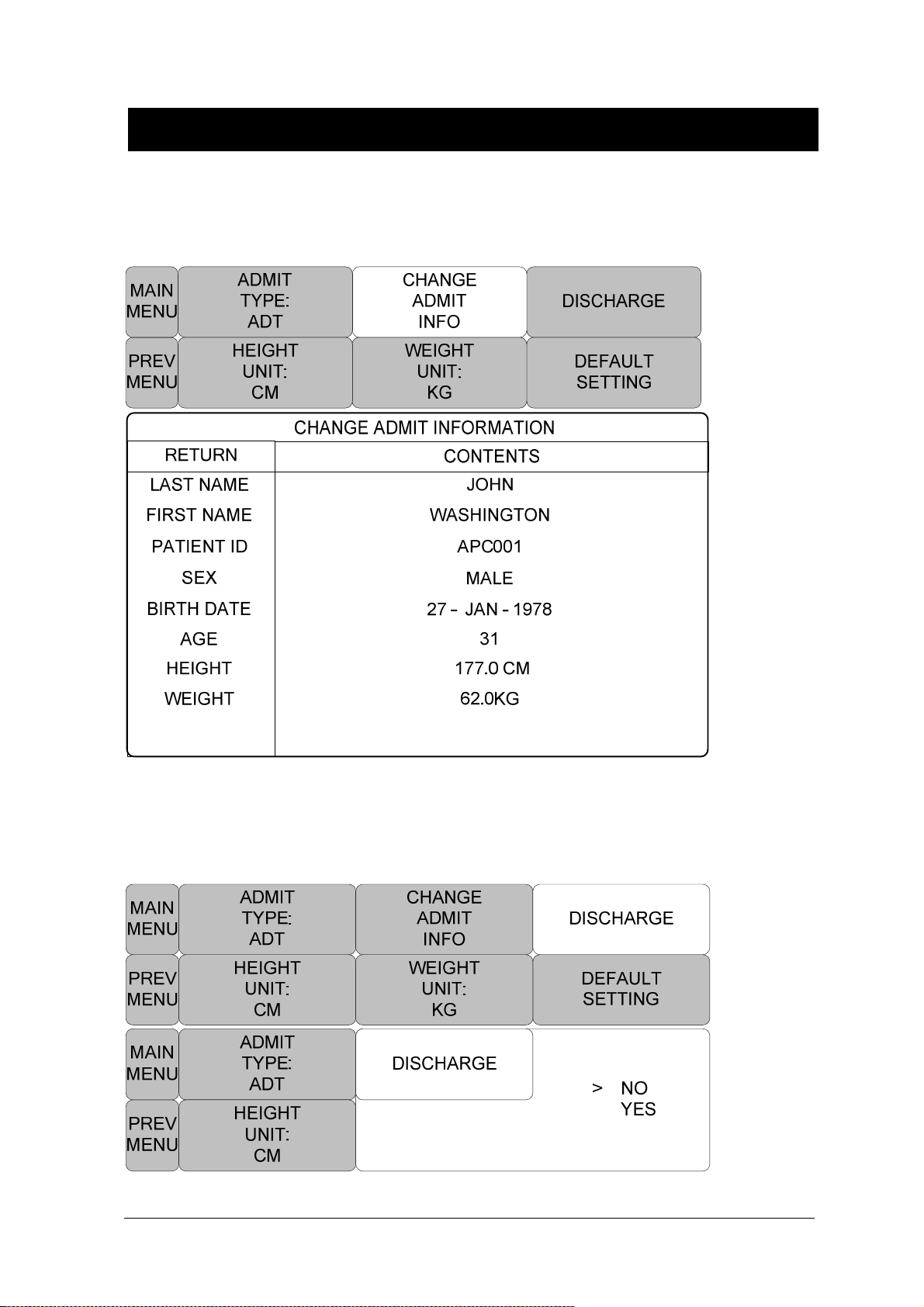
BM3 User’s Manual
CHANGE ADMIT INFO
Last and first name (11 letters for each), sex (male or female), date of birth, weight, height, and
patient ID (11 characters)
DISCHARGE ( Discharge Patient )
Patient information and all numbers change to standard, and the screen displays, “ALL ALARMS
OFF ADMIT PATIENT TO ACTIVE ALARMS.”
Rev. 2.61 2. PATIENT/DATA MANAGEMENT 57
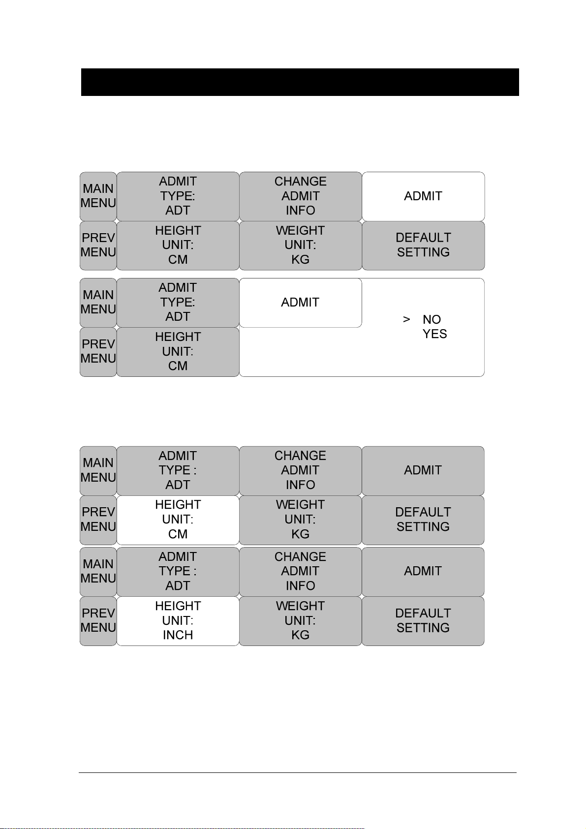
BM3 User’s Manual
ADMIT( Admit patient )
Depending on how your monitor is set up, you will see either ADMIT patient or new case.
HEIGHT
Unit of height is set as Cm / Inches.
Rev. 2.61 2. PATIENT/DATA MANAGEMENT 58

WEIGHT
Unit of weight is set as Kg / LBS.
BM3 User’s Manual
DEFAULT SETTING
Resets the Alarm Limit settings to factory defaults as in “12.DEFAULT SETTING VALUE” section.
Rev. 2.61 2. PATIENT/DATA MANAGEMENT 59

BM3 User’s Manual
2.2 ALARM
Alarm is divided into two, alarm for the patient’s condition and for the product’s condition.
The patient’s alarm sounds when the diagnostic functions (ASYSTOLE, VTAC/VFIB, and VTAC) are
detected. Each alarm sound differs in order in order and volume according to the levels of HIGH,
MEDIUM, LOW and MESSAGE.
HIGH
MEDIUM
LOW
MESSAGE
: Alarm sounds
-5
-3
-1
250
: Number flashes
: Waves are printed out
Rev. 2.61 2. PATIENT/DATA MANAGEMENT 60
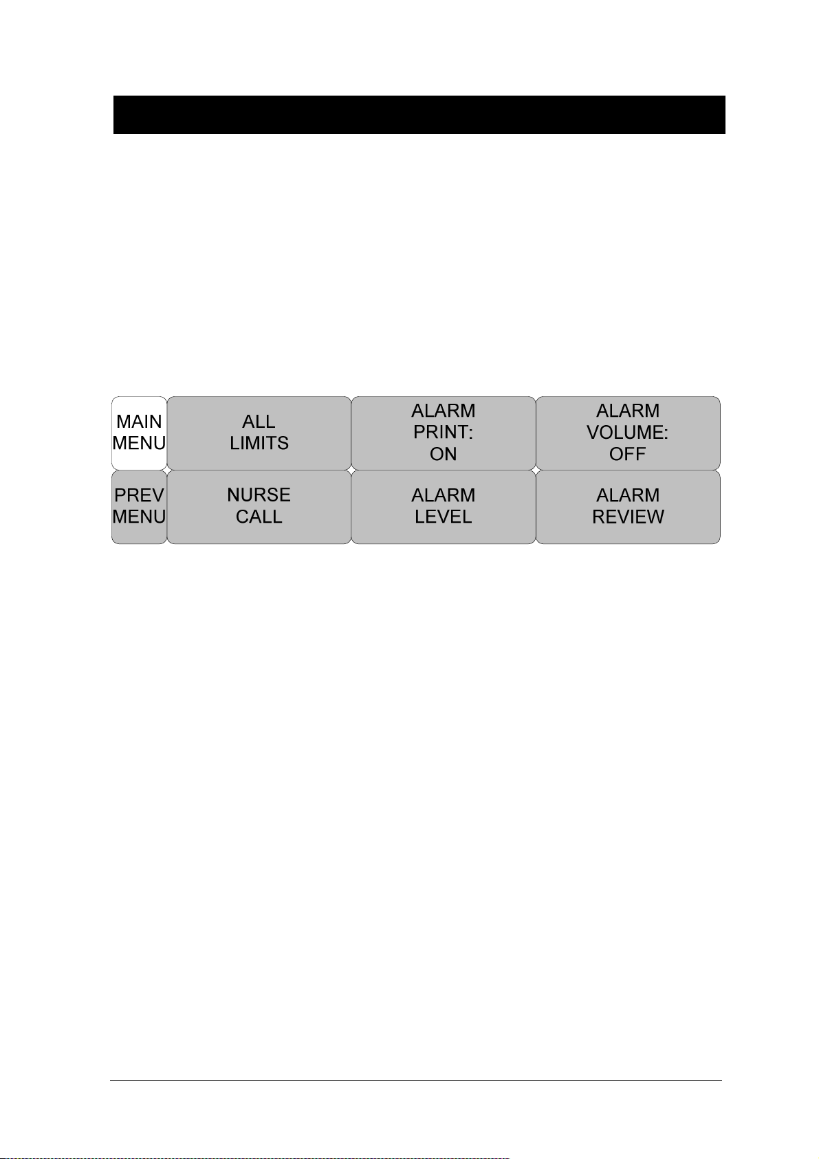
BM3 User’s Manual
ALARM LIMITS:The machine enables one to see and change the limits of alarm for all parameter
functions.
ALARM PRINT:with an ON/OFF setup, the related information is printed out whenever an alarm is
given.
ALARM VOLUME:volume of each alarm can be adjusted in 10 step.
ALARM LEVEL:Priority of each parameter alarm can be set up.
ALARM REVIEW: Shows the priority order information for all alarms of each measurement.
NURSE CALL: Set the feature of the NURSE CALL.
Rev. 2.61 2. PATIENT/DATA MANAGEMENT 61

BM3 User’s Manual
ALL LIMITS
It is able to see all the alarm range and change of measurement function.
ALARM PRINT
Set ON/OFF functions automatically. When the alarm is activated the corresponding information is
printed on heat sensitive paper. Alarm level upper than MEDIUM Level. But, LEAD FAULT AND
LOW BATTERY Alarm isn’t activated the alarm print when alarm is set.
Rev. 2.61 2. PATIENT/DATA MANAGEMENT 62
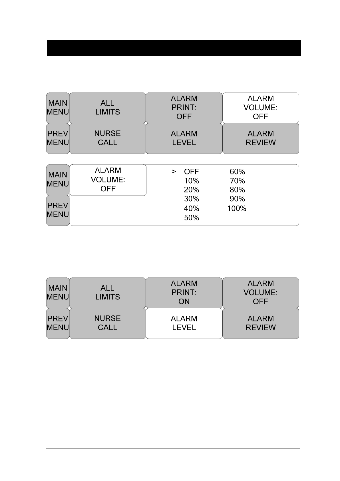
BM3 User’s Manual
ALARM VOLUME
Set the alarm volume to be set at 10 grades.
ALARM LEVEL
Set the order of priority in each alarm.
Rev. 2.61 2. PATIENT/DATA MANAGEMENT 63

PARAMETER LEVEL
BM3 User’s Manual
PARAMETER ALARM LEVELS
RETURN
ALARM LEVEL
HR MEDIUM
SPO2-% MEDIUM
SPO2-R LOW
RESP MESSAGE
RESP-A MESSAGE
NIBP MEDIUM
TEMP MESSAGE
LOW BATTERY MEDIUM
Rev. 2.61 2. PATIENT/DATA MANAGEMENT 64
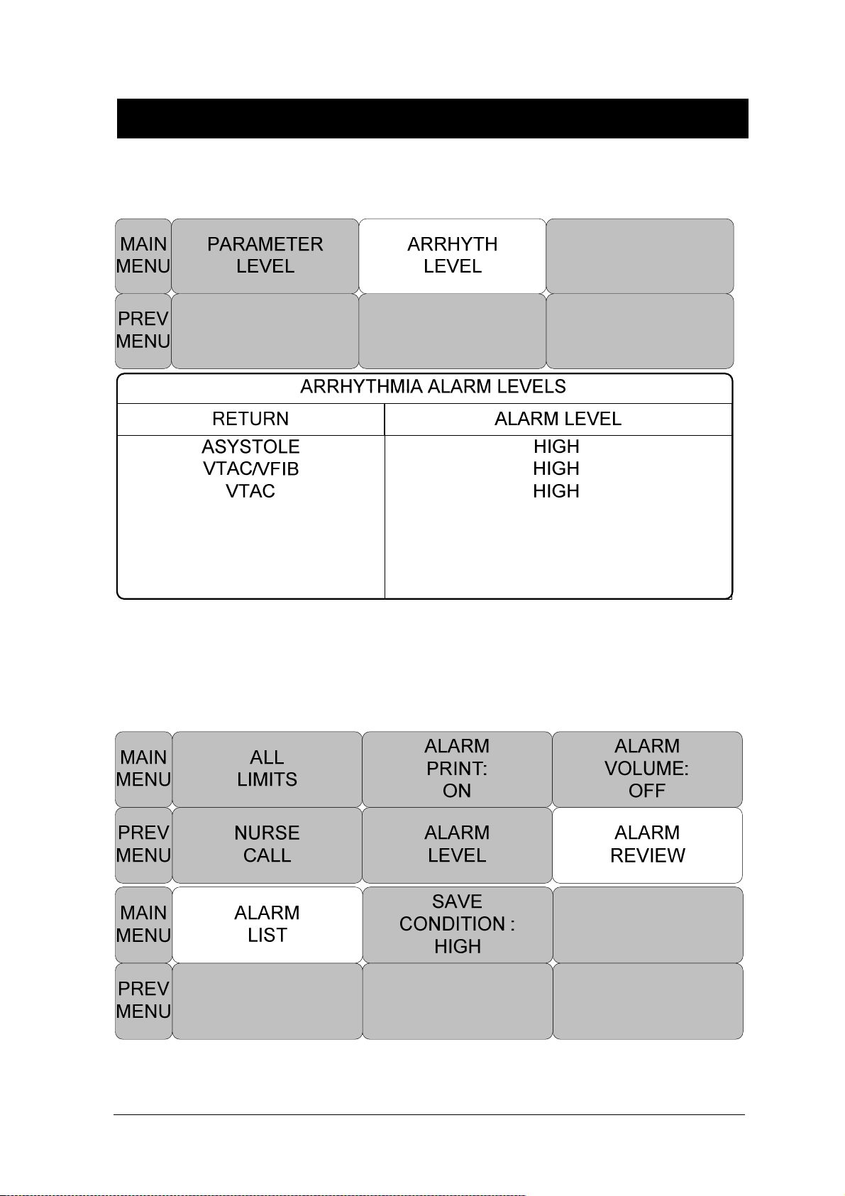
BM3 User’s Manual
ARRHYTH LEVEL
One can set up priorities when he or she uses the alarm for the diagnostic function.
ALARM REVIEW
After an alarm is triggered the alarms and data wave pattern can be reviewed. Set up for priority of
each parameter alarm.
Rev. 2.61 2. PATIENT/DATA MANAGEMENT 65
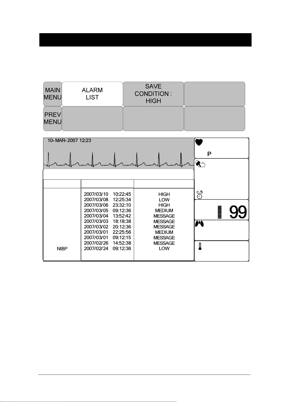
BM3 User’s Manual
ALARM LIST
When an alarm activates, this shows the order of the alarms.
100
50
BPM
80
mmHg
John
PVC (0/min): 0
x2
II
ST(mm):
0.0
ALARM REVIEW
RETURN TIME KIND
III
ECG
SPO2
RESP
ECG
SpO2
ECG
ECG
SPO2
SPO2
RESP
II
RR II
RESP
X2
X1
Ver.4.00BHCDDC
150
60
ADT
09:30
1HR
2:10
PR
30
10
‘C
39.0
35.0
80
RPM
120
%SpO2
36.7
80
(93)
100/90
30S
20
Rev. 2.61 2. PATIENT/DATA MANAGEMENT 66
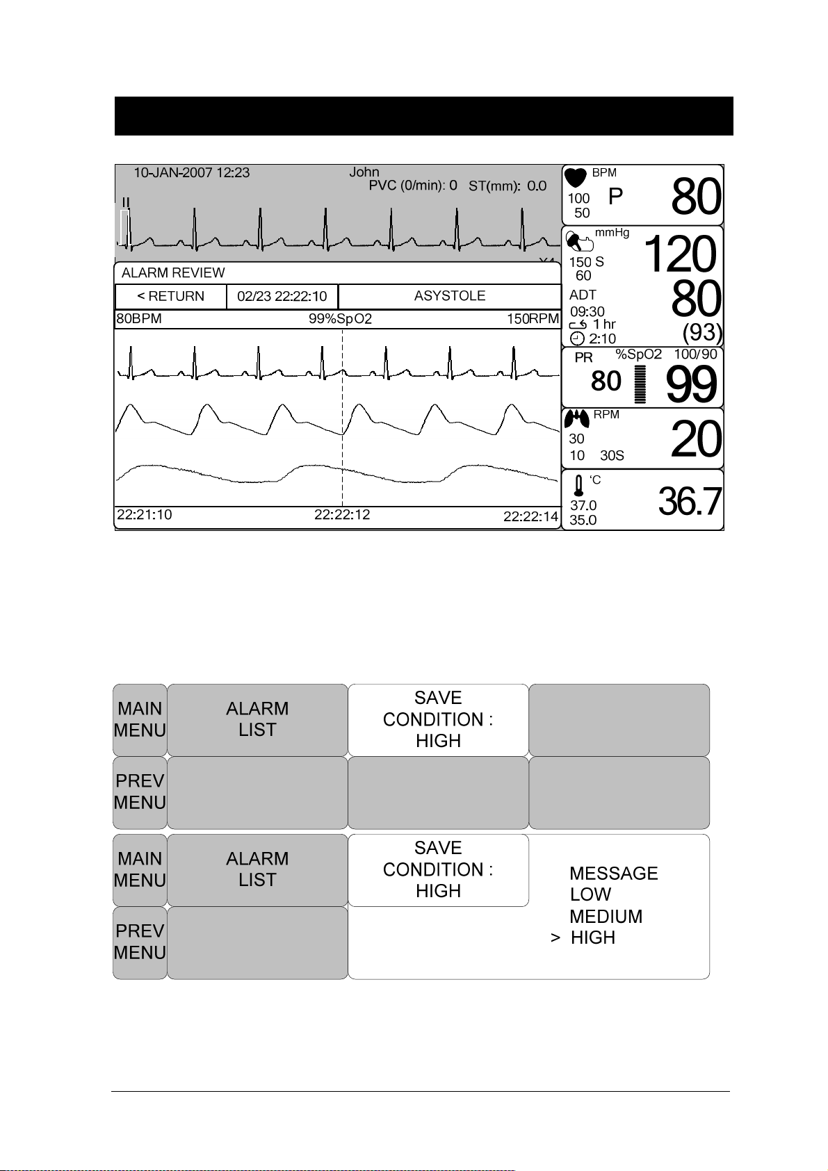
BM3 User’s Manual
SAVE CONDITION
This determines the order in which triggered alarms are saved.
Rev. 2.61 2. PATIENT/DATA MANAGEMENT 67
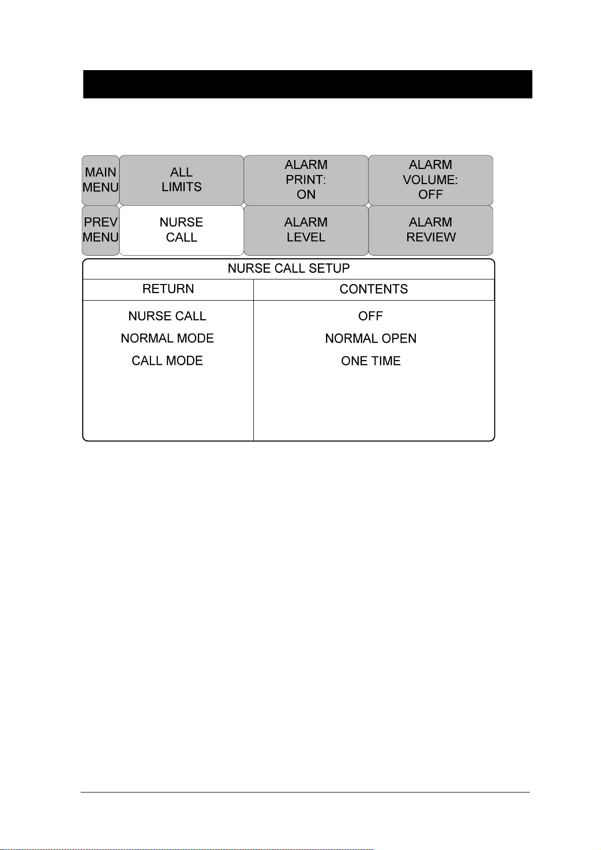
BM3 User’s Manual
NURSE CALL
When an alarm is triggered, this activated the NURSE CALL function.
1. NURSE CALL : ON/OFF
- The nurse call function is enable or disable.
2. NORMAL MODE
- NORMAL OPEN : Select this option when the hospital’s call system is set to NORMAL
OPEN.
- NORMAL CLOSE : Select this option when the hospital’s call system is set to
NORMAL CLOSE.
3. CALL MODE
- ONE TIME : When ONE TIME is selected.
a nurse call signal is a pulse signal lasting
3s. When multiple alarms occur simultaneously, only one pulse signal will be
output..
- CYCLING :
When
CYCLING
is selected, the duration of a nurse call signal is the
same with the alarm, namely, from the time that the alarm occurs to the time it
disappears. On and off repeatedly at intervals of 1 second.
- CONTINUE : When CONTINUE is selected,
the duration of a nurse call signal is the
same with the alarm, namely, from the time that the alarm occurs to the time it
disappears. However, lasts only one minute, then stops.
Rev. 2.61 2. PATIENT/DATA MANAGEMENT 68

3. SETUP
3.1 SETUP
DISPLAY
SET PARA
WAVE SELECT
SET DATE & TIME
HR SOURCE
SWEEP SPEED
KEY SOUND
DEMO
USER SERVICE
SET UNIT NAME
SET BED NUMBER
AC FILTER
SYSTEM
W-LAN
DISPLAY MODE
MAKER SERVICE
FREEZING AND UNFREEZING
Rev. 2.61 69
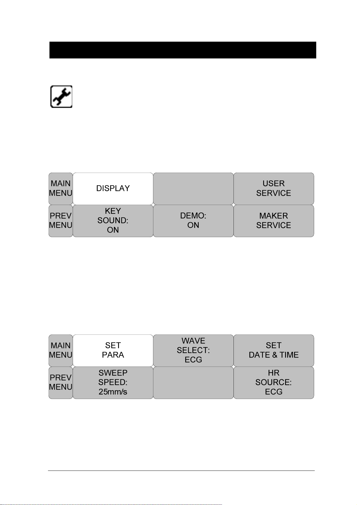
BM3 User’s Manual
3.1 SETUP
DISPLAY : screen set menu
USER SERVICE : This is the menu to set the connection used to interface with an external
computer
MAKER SERVICE : This is the basic adjustment menu used to adjust the features of this product.
DISPLAY
SET PARA:Measurement function selected.
WAVE SELECT:Set wave pattern source at the bottom of the WINDOW with LARGE
SET DATE & TIME: Set and change date and time.
HR SOURCE :Set and select ECG(HR) / SpO2(PR) source.
SWEEP SPEED : Set speed of ECG, SpO2 WAVE DISPLAY
Rev. 2.61 3.SETUP 70
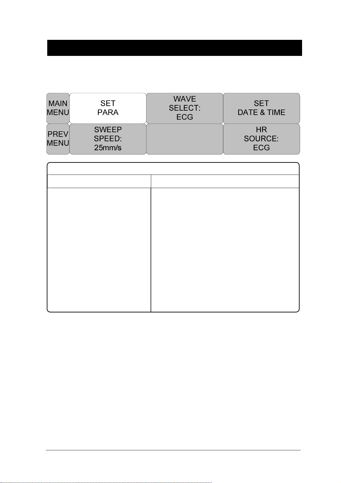
SET PARA
Select measurement function to use
PARAMETER WINDOW SET
RETURN WINDOW ON/OFF
BM3 User’s Manual
ECG
SPO2
RESP
NIBP
ON
ON
OFF
OFF
TEMP ON
Rev. 2.61 3.SETUP 71

BM3 User’s Manual
WAVE SELECT
Select waveform to display in large parameter display.
SET DATE & TIME
It has sub menu to set date and time.
Rev. 2.61 3.SETUP 72

SET TIME
Set time of equipment.
BM3 User’s Manual
SET DATE
Set date of equipment
MAIN
MENU
DATE:
PREV
MENU
SET
06-MAR-2007
Rev. 2.61 3.SETUP 73
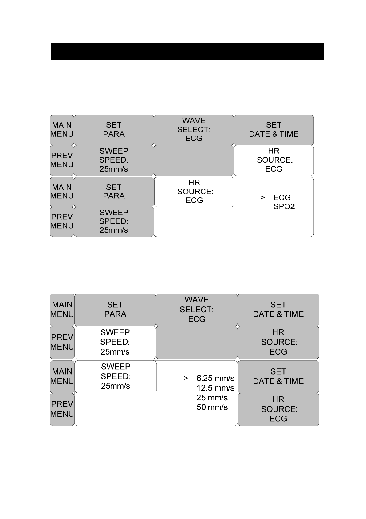
BM3 User’s Manual
HR SOURCE
This menu is used to set the source that detects heart and pulse rate.
The source can select among ECG and SPO2.
SWEEP SPEED
Set speed of drawing wave signal pattern in this widow.
Rev. 2.61 3.SETUP 74

BM3 User’s Manual
KEY SOUND
Set ON/OFF Key Sound of equipment.
DEMO
Set ON/OFF DEMONSTRATION of equipment.
Rev. 2.61 3.SETUP 75

BM3 User’s Manual
USER SERVICE
The user is able to set the set UNIT NAME, BED NUMBER, external Wireless equipment power ,
communication parameters, display mode , and power supply filter.
SET UNIT NAME
Set up for UNIT( CCU,ICU,ER,etc.) name.
Rev. 2.61 3.SETUP 76

BM3 User’s Manual
SET BED NUMBER
Set up for patient bed number.
Allowable setters are from 0~ 9, A ~ Z .
AC FILTER
AC FILTER is function where you can set power supply frequency. This feature is required because
power supply frequency can be different from one country to another. . (The selectable frequencies
are 50Hz and 60Hz.)
Rev. 2.61 3.SETUP 77

BM3 User’s Manual
SYSTEM
System able to change and verify Equipment version information and system information
VGA OUTPUT : VGA output on the output board provides.
CENTRAL : ON / OFF function of the network system used to set.
HL7 : ON/OFF function of HL7 network protocol.
Will turn ON after setting the equipment off and connected to the Central system or HL7 system
NAK : ON/OFF function of transmission control of HL7 protocol
DHCP : ON/OFF function of allocation IP address automatically.
HOST IP, DEVICE IP, SUBNET and GATEWAY: Set the information for connecting to the Central
system.
Warning
We recommend to use a static IP outside the DHCP range
Rev. 2.61 3.SETUP 78

BM3 User’s Manual
W-LAN
W-LAN power can be supplied for enabling a External wireless LAN equipment use.
DISPLAY MODE ( MONITOR or SPOT )
You can selected Monitoring display mode or Spot display mode.
MAKER SERVICE
Maker service is a menu is used by manufacturers.
Rev. 2.61 3.SETUP 79

BM3 User’s Manual
Freezing and Unfreezing
- This icon is pressed to freeze waveforms. All displayed waveforms are frozen.
The waveforms are frozen for 1 minutes or until they are unfrozen.
Press the “F” key is unfrozen with large parameter mode.
When the waveforms are frozen, the “FREEZE” message appears with the frozen time.
- Press the FREEZE icon ( Unfreezing icon ) on the control panel again. After exiting the
frozen screen, new real time waveforms are displayed.
Rev. 2.61 3.SETUP 80

4. TREND
4.1 TREND
GRAPHIC TREND
TABULAR TREND
TREND WINDOW SETUP
Rev. 2.61 81
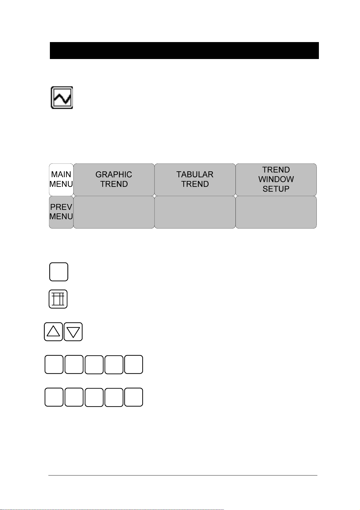
BM3 User’s Manual
4.1 TREND
TREND shows saved data graphically displayed with numeric values.
Real-time data recording duration is 1 minute. Amount of saving time is for this data will be saving
for 128hours.
R
0.5
1
: Move to main screen
: Move within the tables
: Move up and down to other analysis function
1 6
5 60
31.5
3015
: Time(HOURS) period set menu at Graphic Trend
: Time(MIN) period set menu at Tabular Trend
Rev. 2.61 4.TREND 82

BM3 User’s Manual
GRAPHIC TREND
Wave Data can be stored and seen according to section.
10 - SEP- 2007 22: 23
x 2
II
John
PVC (/min): 0 ,
ST(m m ) : 0.0
GRA PHI C TR EN D 1 0- S EP- 2007 13:00
III
HR ( 8 0) S T ( 0.0 ) PVC ( 0 ) RR ( 2 0)
30 0B PM 20.0mm 1 00/ mi n 150RPM
SpO2
16 5 0 50 75
II
RR II
0 - 20 .0 0 0
12: 00 12: 3 0
0.5 1
1.5
3 6
Ver . 4.00 B HCDDC
X2
X1
10 0
50
15 0
60
A DT
09 : 30
0: 5 7
PR
30
10
39 . 0
35 . 0
B PM
P
m m Hg
1 h r
RPM
‘
C
%Sp O2
10 0/ 90
30 S
Rev. 2.61 4.TREND 83

BM3 User’s Manual
TIME PERIOD
One can set up and store data and time that one can see in a screen.
0.5
1 6
31.5
Rev. 2.61 4.TREND 84
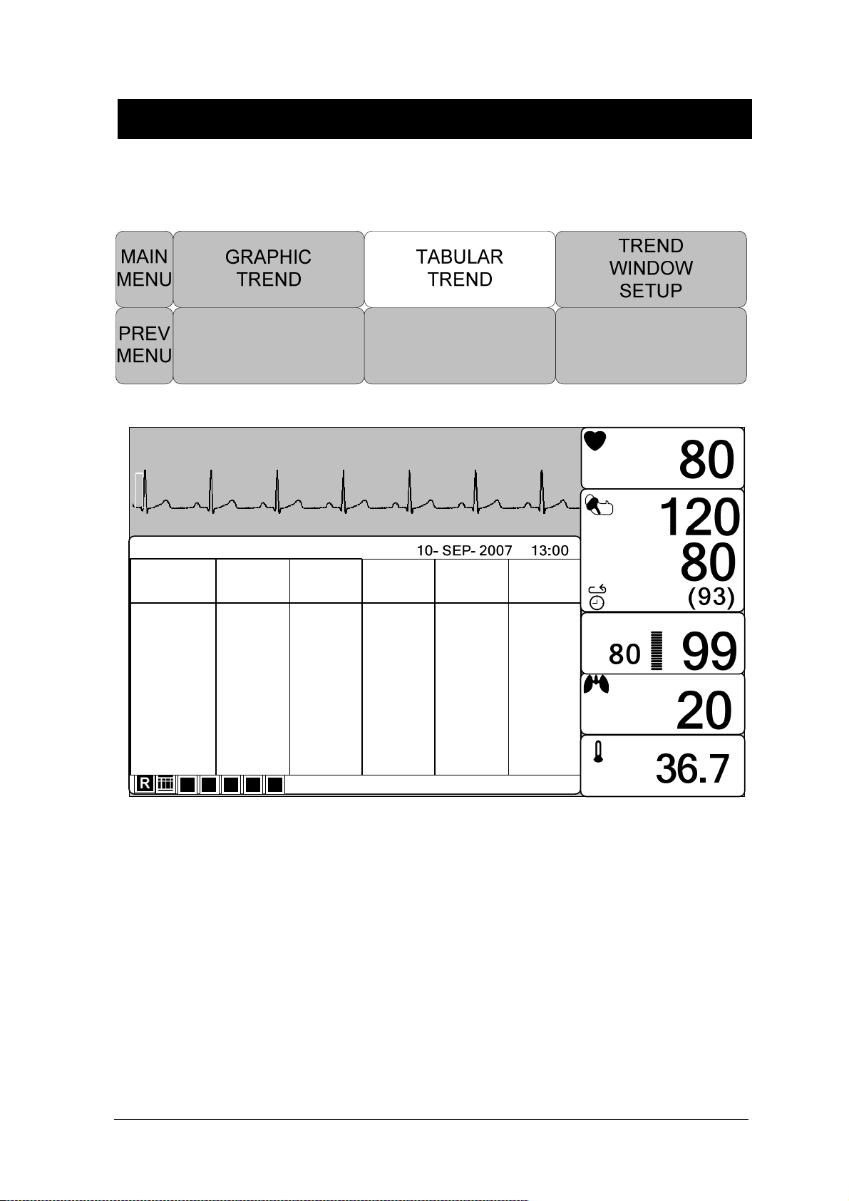
BM3 User’s Manual
TABULAR TREND
One can see the stored data at the time previously set up.
10 - SEP- 2007 13: 30
x 2
II
John
PVC (0/min): 0
ST(m m ) : 0 .0
10 0
50
B PM
P
m m Hg
TABULAR TREND
III
HR
SPO2- %
SPO2- R
SpO2
RESP
NI B P- S
NIB P- M
NIB P- D
II
TEMP
RR II
ST
PVC
1
10- SEP
15 30 60
5
12 : 10
80
99
80
20
12 0
93
80
36 . 7
0.0
0
10 - SEP
12 : 09
80
99
80
20
12 0
93
80
36 . 7
0. 0
0
10 - SEP
12: 08
80
99
80
20
12 0
93
80
36 . 7
0. 0
0
10- SEP
12 : 07
80
98
80
20
120
93
80
36 . 7
0.0
0
Ver . 4.00B H CDDC
10 - SEP
12: 06
80
99
80
20
12 0
93
80
36 . 7
0. 0
0
X2
X1
150
60
ADT
09: 30
1 h r
2:1 0
PR
30
10
‘
C
39 . 0
35 . 0
%Sp O2
RPM
10 0/ 90
30S
Rev. 2.61 4.TREND 85

TIME INTERVAL
One can store data and set up time.
1
5 60
3015
10 - SEP- 2007 13: 30
x 2
II
TABULAR TREND
III
HR
SPO2- %
SPO2- R
SpO2
RESP
NI B P- S
NIB P- M
NIB P- D
II
TEMP
RR II
ST
PVC
1
10- SEP
15 30 60
5
12 : 10
80
99
80
20
12 0
93
80
36 . 7
0.0
0
10 - SEP
12 : 09
80
99
80
20
12 0
93
80
36 . 7
0. 0
0
BM3 User’s Manual
John
PVC (0/min): 0
10 - SEP
12: 08
80
99
80
20
12 0
93
80
36 . 7
0. 0
0
ST(m m ) : 0 .0
10- SEP
12 : 07
80
98
80
20
120
93
80
36 . 7
0.0
0
Ver . 4.00B H CDDC
10 - SEP
12: 06
80
99
X2
80
20
12 0
93
80
36 . 7
0. 0
0
X1
10 0
50
150
60
ADT
09: 30
1 h r
2:1 0
PR
30
10
‘
C
39 . 0
35 . 0
B PM
P
m m Hg
%Sp O2
RPM
10 0/ 90
30S
TREND WINDOW SETUP
Set the trend display window that will show the real time wave window.
Rev. 2.61 4.TREND 86

BM3 User’s Manual
TIME PERIOD
Set visible time period in a screen.
Rev. 2.61 4.TREND 87
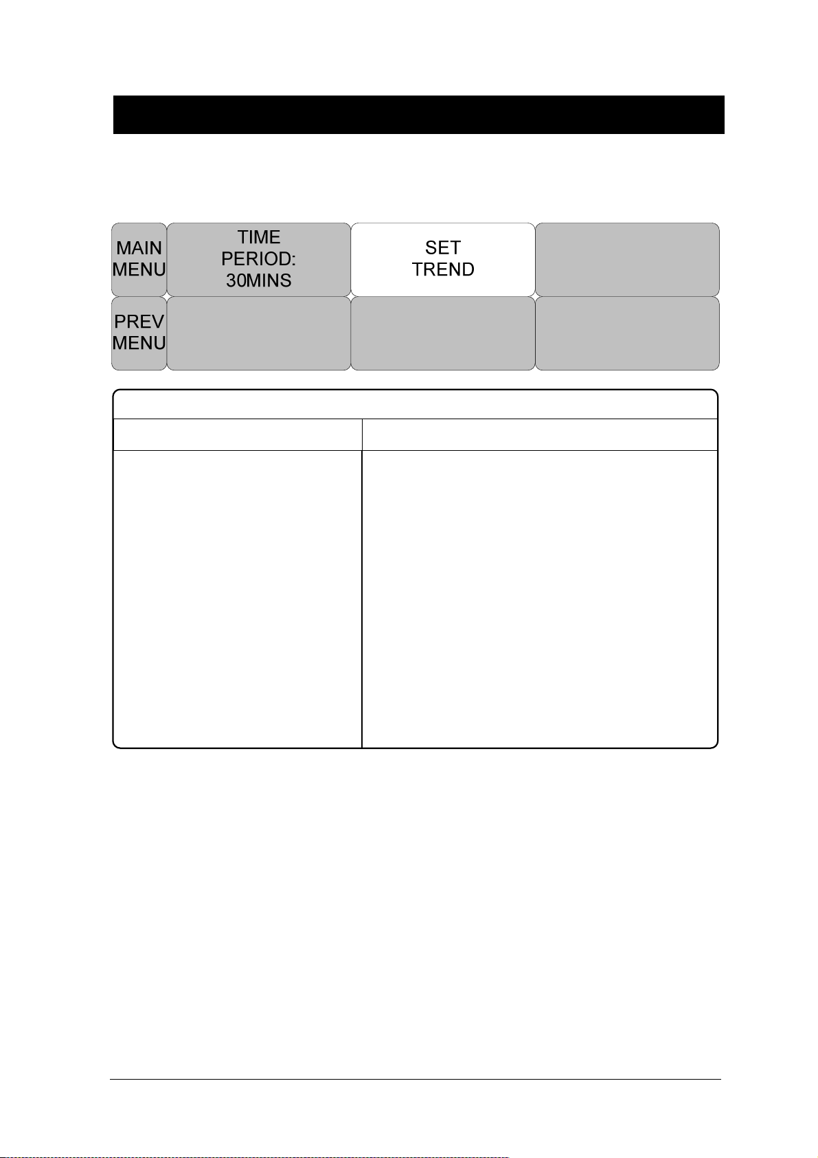
SET TREND
Set parameter for display in a screen.
PARAMETER WINDOW SET
RETURN ON / OFF
BM3 User’s Manual
TREND PRINT
HR
ST
SPO2
PR
ON
ON
ON
ON
RESP ON
NIBP
TEMP
ON
ON
Graphic: select the number which selects a graphic trend and press print to prints the selected
trend.
Table: select the table number to be print and press print to receive print all the data in the selected
patient admit (Admit) table.
Rev. 2.61 4.TREND 88

5. ECG
5.1 Outline
Color and Standards of Cables
Position of ECG Connector and Measurement Cable
Attaching Electrodes to the Patient
Choosing an ECG lead for Arrhythmia Monitoring
Information on the ECG waveform
5-Lead Electrode Placement
3-Lead Electrode Placement
Electrode Placement for Neonates
5.2 ECG Data Window
5.3 ECG Setup
LEAD SELECT
ALARM LIMIT
ALARM LEVEL
ALARM SOUND
QRS VOLUME
DISPLAY
ECG SWEEP SPEED
ECG SIZE
HR SOURCE
ANALYSIS SETTING
Rev. 2.61 89
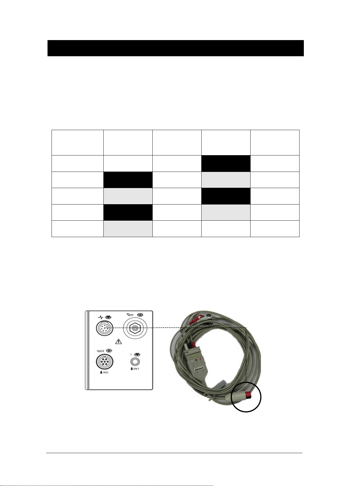
BM3 User’s Manual
5.1 Outline
It calculates the heart rate with 3 or 5 leads ECG signal acquisition and perform the alarm according
to the setting value.
Colors and Standards of Cables
Leadwire
AHA
Color code
Right arm White RA Red R
Left arm Black LA Yellow L
Right leg Green RL Black N
Left leg Red LL Green F
V1(precordial) Brown V1 White C1
AHA:American Heart Association (U.S.A. standard)
IEC:International Electro technical Commission (Europe standard)
AHA
Label
IEC
Color code
Position of ECG Connector and Measuring Cable
ECG connecter +detect cable
IEC
Label
Rev. 2.61 5.ECG
90

BM3 User’s Manual
Attaching Electrodes to the Patient
1. Shave excess hair. With a piece of cotton pad moistened with alcohol, clean the patient’s skin
where the electrodes should be mounted. Avoid wrinkled or uneven skin areas. Wipe off the alcohol
with a dry cotton pad.
2. Open the electrode package and take out the electrode.
3. Remove the backing paper from the electrode. Be careful not to touch the adhesive side.
4. Attach the disposable electrode to the previously cleaned skin. Avoid wrinkled and uneven skin
areas.
5. The electrode lead which is connected to the monitor onto the electrode.
6. Fasten the electrode lead to the skin with surgical tape with an extra length of wire between the
tape and the electrode. This prevents body movement from moving the electrode lead.
Note
To maintain good contact between the electrode and skin, check that the paste of the
disposable electrode is not dry.
When contact of the disposable electrode becomes poor, replace the electrode with a
new one immediately. Otherwise, contact impedance between the skin and electrode
increase and the correct ECG cannot be obtained.
If the contact is bed before the expiration date on the package, replace the electrode with
a new one.
To obtain a stable ECG waveform rub the skin with “skin Pure” skin preparation gel or
tincture of Benzion.
Shall use only the CE certified disposable electrode.
Rev. 2.61 5.ECG
91

BM3 User’s Manual
Choosing an ECG lead for Arrhythmia Monitoring
It is very important to select a suitable lead for arrhythmia monitoring.
Guidelines for non-paced patients:
QRS should be tall and narrow(recommended amplitude > 0.5mV)
R wave should be above or below the baseline (but not bi-phasic)
T wave should be smaller than 1/3 R-wave height.
The P-wave should be smaller than 1/5 R-wave height.
For paced patients, in addition to the above,:
Not wider than the normal QRS
The QRS complexes should be at least twice the height of pace pulses.
Large enough to be detected, with no re-polarization.
To prevent detection of P-waves or baseline noises as QRS complexes, the minimum detection
level for QRS complexes is set at 0.15mV. Adjusting the ECG wave size on the monitor
display(gain adjustment)does not affect the ECG signal which is used for arrhythmia analysis. If the
ECG signal is too small, you may get false alarms for asystole.
Information on the ECG waveform
When ECG signal is 80bpm T-wave duration is 180ms, and the QT interval is 350ms.
Rev. 2.61 5.ECG
92
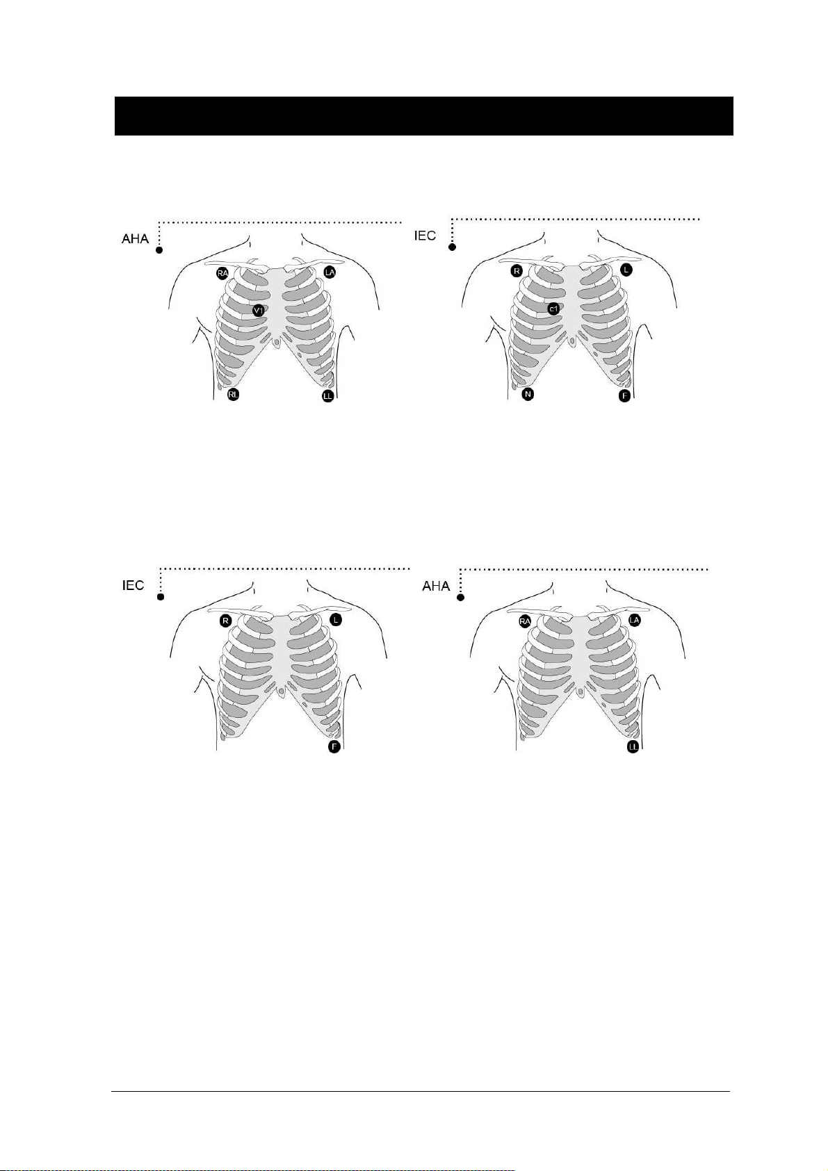
5-Leadwire Electrode Placement
BM3 User’s Manual
3-Leadwire Electrode Placement
Rev. 2.61 5.ECG
93

BM3 User’s Manual
Electrode Placement for Neonates
Rev. 2.61 5.ECG
94

5.2 ECG Data Window
BM3 User’s Manual
Heart Rate Alarm Limit:
Decides the QRS limits, and
gives an alarm if a value is over
the limits.
ECG Wave Display is always on when the cable is connected.
100
50
QRS: Detects QRS, and
flashes when QRS is
detected.
BPM
P
Note
80
Pace Detector
Indicators:
Detects and displays
the patient’s pace
maker and flashes.
Heart Rate:
Displays heart rate per minute.
The heart rate is calculated by a moving average. The monitor detects 8 consecutive beats,
averages the R-R intervals of the latest 8 beats and uses this average to calculate the current
heart rate. When a new beat is detected, the heart rate is recalculated using the latest 8beats. The
heart rate display is updated every 3 seconds.
Heart rate meter updates a new heart rate for a step increase or decrease in 10 seconds maximum.
When ventricular tachycardia is detected, the alarm set in 5 seconds maximum.
Check that the delay time of the output signal (alarm trigger 80ms maximum) is within the range of
the connected equipment.
Rev. 2.61 5.ECG
95

BM3 User’s Manual
Safety Precautions
Warning
CABLES — Route all cables away from patient's throat to avoid possible strangulation.
CONDUCTIVE CONNECTIONS — Extreme care must be exercised when applying medical
electrical equipment. Many parts of the human/machine circuit are conductive, such as the
patient, connectors, electrodes, transducers. It is very important that these conductive parts do
not come into contact with other grounded, conductive parts when connected to the isolated
patient input of the device. Such contact would bridge the patient's isolation and cancel the
protection provided by the isolated input. In particular, there must be no contact of the neutral
electrode and ground.
DEFIBRILLATION — Do not come into contact with patients during defibrillation. Otherwise
serious injury or death could result.
To avoid the risk of serious electrical burn, shock, or other injury during defibrillation, all persons
must keep clear of the bed and must not touch the patient or any equipment connected to the
patient.
After defibrillation, the screen display recovers within 10seconds if the correct electrodes are
used and applied in accordance with the manufacturer’s instructions.
ECG cables can be damaged when connected to a patient during defibrillation. Check cables
for functionality before using them again.
The peak of the synchronized defibrillator discharge should be delivered within 60ms of the
peak of the R wave. The signal at the ECG output on the patient monitors is delayed by a
maximum of 30ms.
If the ECG waveform on the screen is too unstable to synchronize with the patient’s heart beat
because of the following reason, remove the cause of an alarm, message, or unstable ECG,
and then use a stable ECG lead for synchronization.
ECG electrode is detached or broken. Lead wire is detached or broken.
Lead wire moves. AC interference, EMG noise or noise from ESU is superimposed.
Connection cable is broken or has a short circuit. Connector has poor contact.
Rev. 2.61 5.ECG
96

BM3 User’s Manual
INTERFACING OTHER EQUIPMENT — Devices may only be interconnected with each other
or to parts of the system when it has been determined by qualified biomedical engineering
personnel that there is no danger to the patient, the operator, or the environment as a result. In
those instances where there is any element of doubt concerning the safety of connected
devices, the user must contact the manufacturers concerned (or other informed experts) for
proper use. In all cases, safe and proper operation should be verified with the applicable
Manufacturer’s instructions for use, and system standards IEC 60601-1-1/EN 60601-1-1 must
be complied with.
Electrosurgery Unit
Electrosurgical units(ESU) emit a lot of RF interference. If the monitor is used with an
ESU,RF interference may affect the monitor operation.
Locate the monitor as far as possible from the ESU. Locate them on opssite sides of the
operating table, if possible.
Connect the monitor and ESU to different AC outlets located as far as possible from each
other.
When using this monitor with an electrosurgical unit, its return plate and the electrodes for
monitoring must be firmly attached to the patient. If the return plate is not attached
correctly,it may burn the patient’s skin where the electrodes are attached.
Rev. 2.61 5.ECG
97
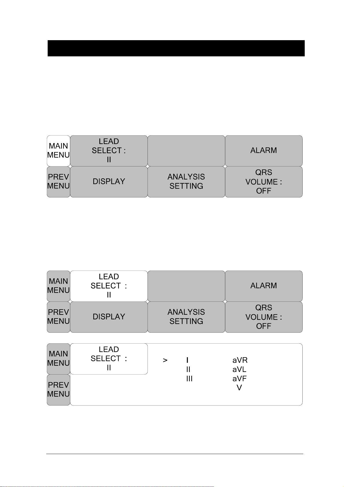
BM3 User’s Manual
5.3 ECG Setup
A setup window appears at lower part of the screen when the Trim Knob Key is pressed in the ECG
Parameter Window.
Selection is made by pressing the Trim Knob Key, while movement across the menu is performed by
turning the key either clock or anticlockwise.
LEAD SELECT
Select channels from I to V in ECG
Rev. 2.61 5.ECG
98
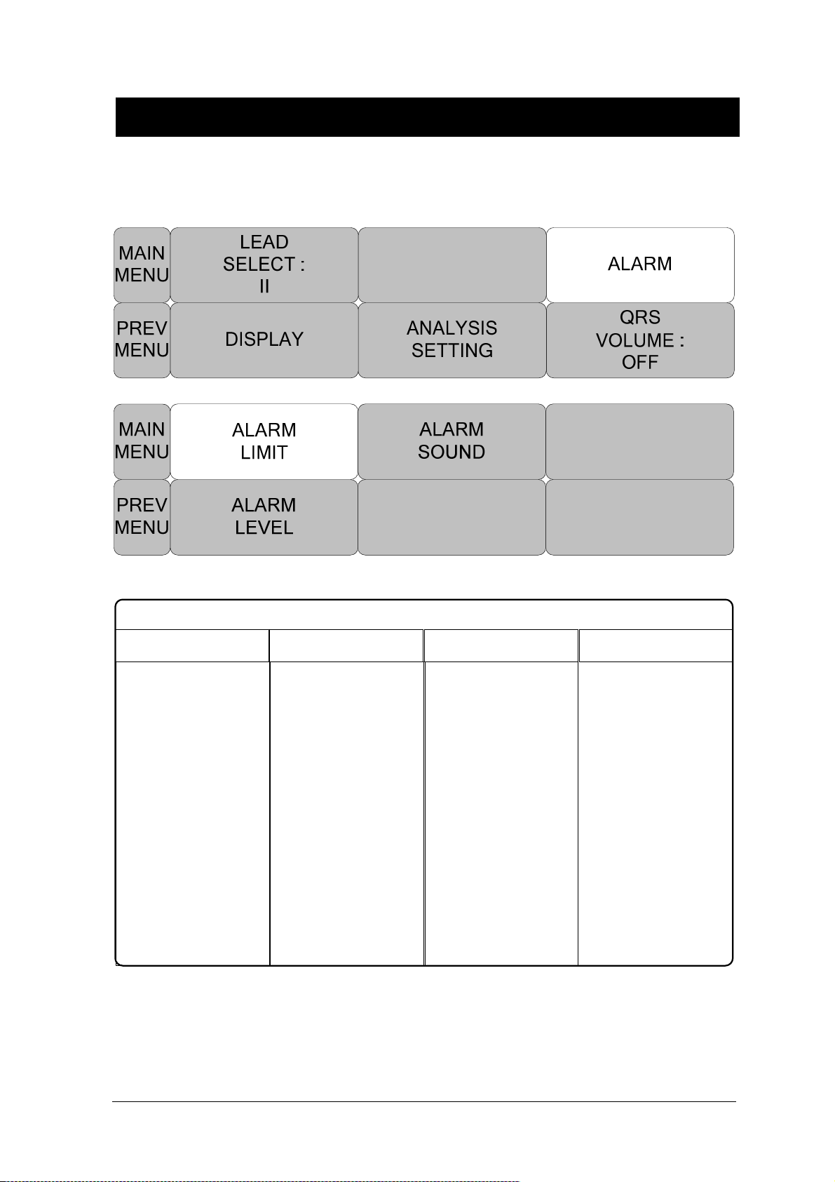
ALARM LIMIT
Alarm Limit is 0 ~ 300.
BM3 User’s Manual
ECG ALARM LIMIT
RETURN UNITS LOW HIGH
HR BPM 60 120
Rev. 2.61 5.ECG
99
 Loading...