

Page 1
查询GHB-0805DU-O供应商
GHB-0805DU-Y
55 Commerce Way
Woburn, MA 01801
(781) 935 - 4442
(781) 938 - 5867
www.gilway.com
GHB-0805DU-O
GHB-0805DU-R
GHB-0805DU-R2
Description
These chip-type LEDs utilize Aluminum Indium Gallium Phosphide
(AlInGaP) material technology.
The AlInGaP material has a very
high luminous efficiency, capable
of producing high light output
over a wide range of drive
currents. The available colors in
this surface mount series are
592 nm Amber, 605 nm Orange,
626 nm Red for AS AlInGaP and
631 nm red for TS AlInGaP.
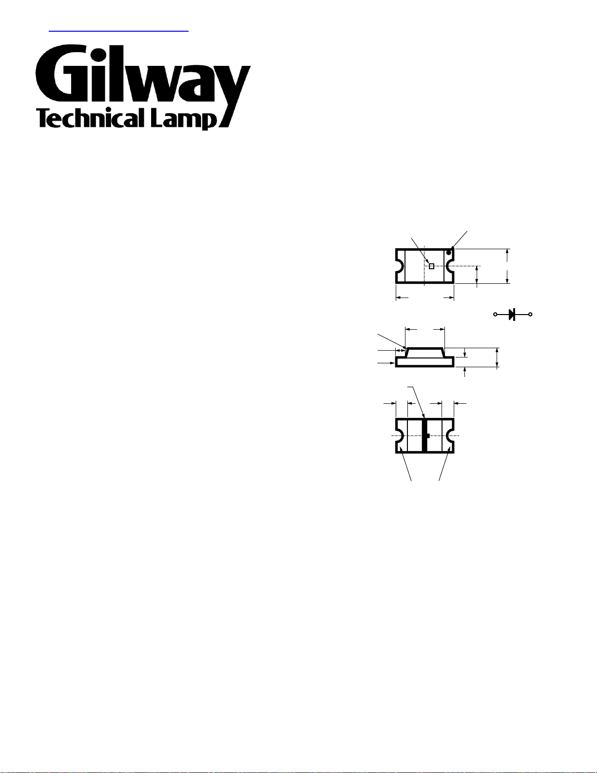
DIFFUSED
EPOXY
0.3 (0.012)
PC BOARD
CATHODE LINE
0.4 ± 0.15
(0.016 ± 0.006)
LED DIE
2.0 (0.079Ê)
1.4
(0.055)
SOLDERING
TERMINAL
CATHODE
MARK
0.62 (0.024)
0.3 (0.012)
0.4 ± 0.15
(0.016 ± 0.006)
1.25 (0.049)
POLARITY
0.8 (0.031)
Page 2
Device Selection Guide
Footprint AS AlInGaP AS AlInGaP AS AlInGaP TS AlInGaP Package
[1,2]
(mm)
2.0 x 1.25 x 0.8
Notes:
1. Dimensions in mm.
2. Tolerance ± 0.1 mm unless otherwise noted.
Amber Orange Red Red Description
GHB-0805DU-Y
GHB-0805DU-O
GHB-0805DU-R
GHB0805DU-R2
Untinted, Diffused
ATbsolute Maximum Ratings
= 25°C
A
GHB-0805DU-Y
GHB-0805DU-O
Parameter Units
DC Forward Current
[1,2]
GHB-0805DU-R
30 30 mA
GHB-0805DU-R2
Power Dissipation 75 81 mW
Reverse Voltage (IR = 100mA) 5 5 V
LED Junction Temperature 95 95 °C
Operating Temperature Range Ð30 to +85 Ð30 to +85 °C
Storage Temperature Range Ð40 to +85 Ð40 to +85 °C
Soldering Temperature See IR soldering profile (Figure 7)
Notes:
1. Derate linearly as shown in Figure 4.
2. Drive currents above 5 mA are recommended for best long term performance.
Electrical Characteristics
= 25°C
T
A
Forward Voltage Reverse Breakdown Capacitance C Thermal
VF (Volts) VR (Volts) (pF), VF = 0, Resistance
@ I = 20 mA @ I = 100m A f = 1 MHz Rq = °(C/W)
F R J-PIN
Parameter Number Typ. Max. Min. Typ. Typ.
GHB-0805DU-Y 1.9 2.4 5 45 300
GHB-0805DU-O 1.9 2.4 5 45 300
GHB-0805DU-R 1.9 2.4 5 45 300
GHB-0805DU-R2 2.2 2.6 5 35 300
Page 3
Optical Characteristics
TA = 25°C
Luminous Color, Viewing Luminous
Intensity Peak Dominant Angle Efficacy
Iv (mcd) Wavelength Wavelength 2 q
Part @ 20 mA
[1]
l
peak
(nm) l
[2]
(nm) Degrees
d
1/2
[3]
h
(lm/w)
Number Color Min. Typ. Typ. Typ. Typ. Typ.
GHB-0805DU-Y AS Amber 25 90 595 592 170 480
GHB-0805DU-O AS Orange 25 90 609 605 170 370
GHB-0805DU-R AS Red 25 90 637 626 170 155
GHB-0805DU-R2 TS Red 40 165 643 631 170 122
Notes:
1. The luminous intensity,Iv, is measured at the peak of the spatial radiation pattern which may not be aligned with the mechanical axis of the
lamp package.
2. The dominant wavelength, ld, is derived from the CIE Chromaticity Diagram and represents the perceived color of the device.
3. q
is the off-axis angle where the luminous intensity is 1/2 the peak intensity.
1/2
v
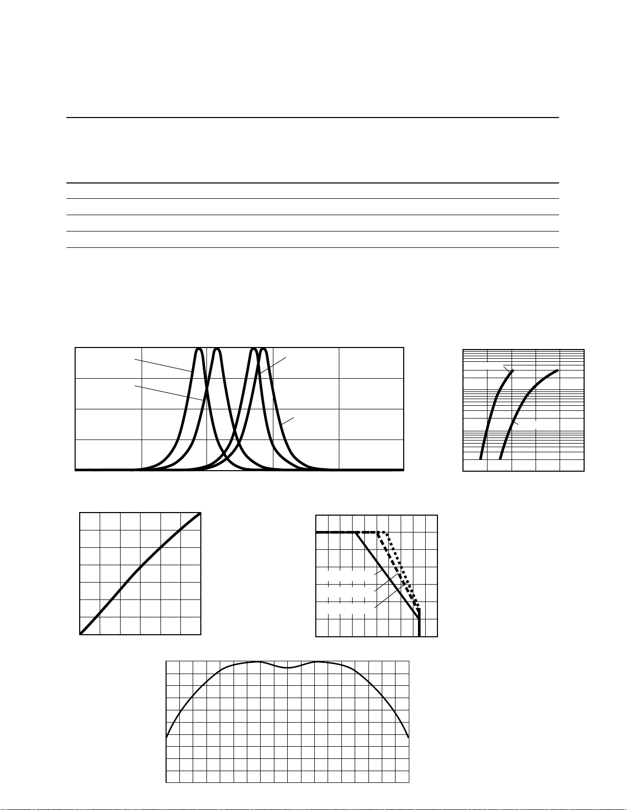
1.0
AS AlInGaP
AMBER
AS AlInGaP
ORANGE
0.5
RELATIVE INTENSITY
0
500 550 600 650 700 750
WAVELENGTH Ð nm
1.4
1.2
1.0
0.8
0.6
0.4
LUMINOUS INTENSITY
(NORMALIZED AT 20 mA)
0.2
0
0 5 15 30
10 20
Ð FORWARD CURRENT Ð mA
I
F
1.00
0.90
0.80
0.70
0.60
0.50
0.40
0.30
RELATIVE INTENSITY
0.20
0.10
0
25
-70 -50
-30 0 20 30 50 70 90-90 -20-80 -60 -40 -10 10 40 60 80
ARSE DAlInGaP
ANGLE
TS AlInGaP
RED
35
30
25
20
Rq
15
Rq
10
Rq
5
Ð MAXIMUM FORWARD CURRENT Ð mA
0
0
F MAX.
I
T
= 800¡C/W
J-A
= 600¡C/W
J-A
= 500¡C/W
J-A
20 60 80 100
40
Ð AMBIENT TEMPERATURE Ð ¡C
A
100
AS AlInGaP
10
1
Ð FORWARD CURRENT Ð mA
F
I
0.1
1.5 1.7 1.9 2.1 2.5
V
Ð FORWARD VOLTAGE Ð V
F
TS AlInGaP
2.3
Page 4

1.2 (0.047)
1.2
(0.047)
0.9
(0.035)
1.2
(0.047)
Recommended soldering pattern for GHB-0805DU-Y/O/R/R2
 Loading...